Abstract— This tutorial session covers recent results using methods that utilize 2-D and 3-D imagery (e.g., from LADAR, visual, FLIR, acoustic-location) to enable aerial vehicles to autonomously detect and prosecute targets in uncertain 3-D environments. This includes segmentation approaches, active contours, adaptive control, estimation theory, and optical flow. Recent flight test results utilizing a small glider and a small helicopter as well as a high-fidelity simulation of multiple airplanes are discussed.
I. INTRODUCTION
HIS tutorial session presentation covers recent simulation and flight test results using methods that utilize 2-D and 3-D imagery (e.g., from LADAR, visual, FLIR, acoustic-location) to enable aerial vehicles to autonomously detect and prosecute targets in uncertain 3-D environments, including capabilities and approaches inspired by those found in nature, and without relying upon highly accurate models of the environment. These capabilities of autonomous sensing and control are enabling Unmanned Aerial Vehicle (UAV) and guided munition operations: in a clandestine/covert manner; in close proximity to hazards, structures, and/or terrain; and in uncertain/adversarial 3-D environments. The purpose of the flight testing is to: ensure that these methods are sound in the sense that they are: (1) implementable in real-time, (2) capable of practical use in the field, and (3) based on realistic/achievable sensor capabilities.
This paper summarizes several high-fidelity simulation
This work was supported in part by AFOSR MURI #F49620-03-1-0401: Active Vision Control Systems for Complex Adversarial 3-D Environments.
E. N. Johnson is the Lockheed Martin Assistant Professor of Avionics Integration, School of Aerospace Engineering, Georgia Institute of Technology, Atlanta, GA 30332-0150 USA (phone: 404-385-2519; e-mail: [email protected]).
A. A. Proctor is a Graduate Research Assistant at the Georgia Institute of Technology, Atlanta, GA 30332-0150 USA. email: [email protected]).
J. Ha is a Graduate Research Assistant at the Georgia Institute of Technology, Atlanta, GA 30332-0150 USA (email: [email protected]).
Y. Watanabe is a Graduate Research Assistant at the Georgia Institute of Technology, Atlanta, GA 30332-0150 USA (email: [email protected]).
and flight test results that utilize the methods described in the main tutorial paper and the other tutorial presentations. Section II covers high-fidelity simulation results of an air-to-air tracking problem. Section III covers an automated visual search system. Section IV covers vision-only glider tests. Section V covers vision-aided INS tests on a helicopter.
II. 6-DOF IMAGE-IN-THE-LOOP SIMULATION
Relative position and velocity estimation approaches are utilized to estimate the 3-D relative position velocity of another aircraft. This is then used to enable, in this case, to follower to maintain formation utilizing 2-D vision as the only sensor providing information about the lead aircraft. Fig. 1 shows a display of the 6-Degree-Of-Freedom (6-DOF) airplane simulator. It includes two airplanes, configured as leader and follower. The follower aircraft has a camera and its image is also simulated. The synthetic images are processed and providing the same type of output we expect in an actual flight of two research aircraft currently under construction.
Fig. 1. 6-DOF image-in-the-loop airplane simulator. Two airplanes (blue=leader, red=follower) are shown. Right top window shows a
Recent Flight Test Results of
Active-Vision Control Systems
Eric N. Johnson, Alison A. Proctor, Jincheol Ha, and Yoko Watanabesimulated camera image and the bottom one displays outputs of the image processor.
The image processor provides a position and size (wingspan) of the leader in camera images [1]. From those measurements, the filter is designed to estimate relative position and velocity between the two aircraft. In order to avoid singularity occasions, a filter state and a measurement vector are chosen as follows.
T b r r r = uT u&T 1 & x , = α u z
where u is a unit vector pointing to the leader, r is the distance between the two aircraft, b is the wingspan of the leader, and α
is the subtended angle of the image of the leader (angular size of the image).We consider the case in which the follower aircraft is guided to change its relative position to the leader obeying a box-shaped command, while the leader flies straight with a constant speed. Fig. 2 shows estimation results of relative position. Here, the position
x
is approximately the range between the two aircraft. The own-ship is guided by its relative position command, which is time varying and shown on the plot. The range tends to be slightly (about 5%) over-predicted due to a small bias in the size measurement process, and might be calibrated for improved results.Fig. 2. Relative position estimation. The Follower is guided by a relative position command (dashed red line).
III. AUTOMATED VISUAL SEARCH
This section describes the design, development, and testing of Unmanned Aerial Vehicles (UAV) with highly automated search capabilities [2]. Here, systems are able to respond on their own in the presence of considerable uncertainty utilizing an image processor, tracker/mapper, mission manager, and trajectory generator algorithms; and to complete a benchmark reference reconnaissance mission.
Subsequent selection of the search area, all functions are automated, and do not require human operator assistance. The resulting system was able to search the 15-building village automatically with speed comparable to a human operator searching on foot or with a conventional remotely piloted vehicle. It was successful in 6 of 7 actual flights over the McKenna Military Operations in Urban Terrain (MOUT) village test site over two different days and a variety of lighting conditions and choice of building.
The GTMax research UAV was utilized for this work, illustrated in Fig. 3, and is based on the Yamaha R-Max Industrial Helicopter airframe, which is normally utilized as a remotely piloted aircraft. The vehicle has a rotor diameter of 10.2 feet, and an weight of approximately 157 pounds [3].
Fig. 3. GTMax Research UAV, utilized to test automated visual search approaches
Fig. 4 shows a flow chart outlining the complete process for the symbol and window detection, classification and tracking. The symbol recognition system looks for line patterns in the images that are similar to the lines generated in a template of the actual symbol. A score from the template match and color classification is then passed to the tracker.
Fig. 4. Flow Chart indicating the process used to identify the building and openings into it (windows or doors).
The window-tracking algorithm looks at the color of each pixel before the image is processed. Then it creates a black and white image that contains only the dark objects. Then the contours around the dark objects are extracted from the image and classified based on the length of the contour. Those objects whose perimeter is an appropriate length are passed to the window tracker along with information about the windows darkness and size. The tracking algorithm is common for both the window and symbol modes. It takes the location and score of each object along with position and attitude information from the primary flight computer, and updates an array containing the position of the objects in the local geographical reference frame. Finally, it calculates a probability for each object based on how many times the object has been seen, the information from the image processor.
Fig. 5 shows the results of the image filter with the centroid and corner results for the windows that were found using the geometric active contours. Since the initial contour is a circular region, only a portion of the image can be evaluated at one time, causing the system to miss openings on the upper floor, and some on the lower floor.
Fig. 5. Identification of windows/doors with active contours.
For window tracking, the geometric active contour method is used to get multiple contours from each image. The contours are broken into individual features, and then geometric characteristics are extracted from the individual contours, which allow the tracker to determine which objects are most likely windows. The contours are extracted from the line image by systematically searching
for lines and then removing the associated contour from the image. This is done using a left-handed removal technique. In this technique, the region around the current pixel is examined to determine in which direction the contour continues. In the event that it continues in more than one direction, the left most contour pixel is followed. The extracted contours are then filtered in post-processing based on their characteristics.
For each window, four sets of geometric data are sent to the tracker: the center of mass, the interior area, the corner locations, and the darkness of the interior. The center of mass is found by averaging the pixel locations over the interior area. Once this is determined, the location of the corners is found. Then the area of the contour can be calculated from the quadrilateral, and the darkness is determined by averaging the grayscale values of each pixel inside of it.
The system described was tested in several ways. First, simulated images were presented to the image processing from a scene generator in the simulator. In these tests, the image-processing job is considerably easier, given the clean characteristics of these synthetic images. However, this is very good test of the object tracking and flight planning components. Three tests were performed searching all 15 buildings of the simulated McKenna MOUT village, and the correct building was selected and a valid opening was found.
Next, tests were conducted at the actual McKenna MOUT village. The initial flight tests were done with a search area including three of the buildings. On all of these tests, the system selected the correct building. In each case, the symbol was placed on a different building. Following this, four attempts were made to search the entire village of 15 buildings. On the first, the actual symbol was missed (missed detection); thrown out because it was considered too bright, presumably due to bright sunlight directly on the symbol unlike all previous tests. The nominal distribution range for the symbol score was changed to account for increased brightness. On all three subsequent tests the correct building was selected based on the symbol, appearing for approximately 5 seconds over a total search flight time of approximately 15 minutes.
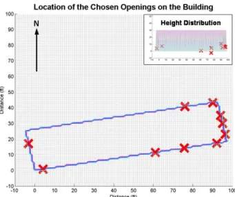
A typical result for the opening search on a single building is shown in Fig. 6. This plot shows a representation of the building with the ten best opening locations from the tracker superimposed. From Fig. 6, it can be seen that the openings are correctly mapped onto the walls of the building, and these positions match actual opening locations accurately. In this case, the aircraft circled the building in a clockwise manner starting at on the northern face. The majority of the openings picked are located on the eastern side; this is possibly due to favorable lighting conditions. The height distribution shows that the system favored the openings on the bottom floor over those on the top.
Fig. 6. Results of one flight which shows the location of the openings mapped onto the building
After searching the selected building for an opening, the UAV would hover in front of the selected opening, pointing the camera at the opening. Fig. 7 shows a typical onboard image hovering in front of the opening, in this case an open door.
Fig. 7. Camera placed with selected building opening in center, in this case an open
IV. VISION-CONTROLLED GLIDER
Here, a guidance, navigation, and control strategy was developed and tested for a small glider, which is capable of flying from a starting point to a ending location using only a single vision sensor [4]. Using only vision to control an aircraft presents a few unique challenges. Firstly, absolute state measurements are not available from an image. Secondly, in order to maintain adequate control of the aircraft, the images must be processed at a fast rate. The image processor utilizes an integral image representation and a rejective cascade filter to find and classify simple features in the images, reducing the image to the most probable pixel location of the objective. The navigation
algorithms use an extended Kalman filter to generate state estimates based on measurements obtained from the imagery. The algorithms are tested through the flight testing of a glider instrumented only with a single camera.
The task chosen to demonstrate the precision of the control strategies is to fly a glider, instrumented with only a camera, at an open window. Since the geometry of the destination is well defined, this objective provides a clear framework for developing guidance, navigation, and control (GNC) laws using only vision. Initiating the flight from a stable platform simplifies the problem slightly, as the operator can ensure that the image processor has properly acquired the target destination prior to launch. To accomplish this, the aircraft needs to be launched from a stationary location at the correct elevation relative to the window.
Four distinct systems are used: the vehicle, the control hardware, the video acquisition/transmission system, and the flight control computer (PFC). The flight control calculations and image processing are performed on a remote computer that can be located separately from the aircraft. The video is transmitted to the PFC using a wireless transmitter; similarly, the control commands are transmitted back to the vehicle through a standard radio-controlled (RC) transmitter. Based on desired flying characteristics and the payload requirements, a meter 2-axis glider was chosen. The glider is equipped with elevator and rudder, and the two meter wing span provides sufficient payload capacity to ensure a very slow stall speed with the additional weight from the video system. The glider with equipment installed is shown in Fig. 8.
Fig. 8. Vision-controlled glider test vehicle, with approximately 2 meter wing span. The camera is located in the nose. The wire running down the tail is going to the video transmitter.
Four measurements are obtained from image processing and camera system (vertical target position, horizontal target position, target size, and target rotation angle). Although additional quantities, such as skew, would help the position estimate, the current image processor cannot realistically make these measurements with accuracy that is
practical.
Fig. 9 shows a photo taken during the flight depicted in the following plots with the results of the image processor. During this flight the image processor tracked the window all the way to the end of the flight, and the glider hit the center of the window. The glider was launched by hand, from an altitude of 15 ft above the window, and the window was approximately 100 ft from the launch site.
Fig. 10 shows the distance estimate from a flight test. The top plot shows the distance to the window. The second plot shows the lateral offset estimate, and the final plot shows the size of the window in the image as the flight progresses. This shows that by the end of the flight the window takes up the entire camera image. Figure 11 shows the attitude estimates.
Fig. 9. Processed onboard image shows black 1-meter square optical target being tracked (center of vertical and horizontal lines) during a flight test
Fig. 10 (top) distance, (middle) lateral offset, and (bottom) target size during a flight test of the vision-only glider
Fig. 11 (top) roll angle, (middle) pitch angle, and (bottom) heading angle during a flight test of the vision-only glider
V. VISION-AIDED INERTIAL NAVIGATION
Past work on vision-based navigation has covered a wide array of specialized topics, including hardware implementation, image processing, trajectory planning, and applications to ground robots [5-10]. Here, we employ an EKF to generate an estimate of the state of an unmanned helicopter from inertial (accelerometers and gyros) and vision measurements. The test platform is the GTMax as in described above [3].
Here, an Inertial Navigation System (INS) aided by 2-D vision sensor looking at a selected image target. By using assumed range (altitude), position in image, size of object in image, and aircraft state, the target object position, size, and orientation is first estimated. Subsequently, measurement of target object position and size in image is to update INS. This enables operation without any other position aiding, such as from the Global Positioning System (GPS).
Target object tracking was greatly enhanced by utilizing the inertial sensor information to maintain tracking across images. This was done by utilizing the changes in position and attitude predicted by these sensors to predict/extrapolate the position of the target in new images. This enabled (for example) for an individual window among a row of windows to be utilized as the optical target in one series of tests.
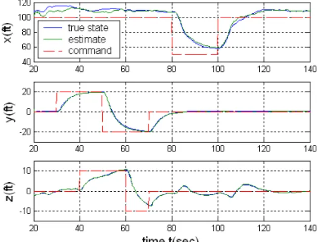
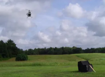
Fig. 12 is a time history for one test, showing longitudinal position (forward/backward). The command is shown as dots, and the raw Differential GPS measurement (not used for navigation) is compared to the vision-aided INS information. In this test, the vision-aided INS solution is the one utilized by the flight control system flying the helicopter, and so it follows the position command. Fig. 13 shows an external picture of one of these tests, showing the helicopter in a hover, and the black optical target in the
lower-right.
Fig. 12. Vision-aided INS position estimation results compared with a Differential GPS measurement. The vision-aided INS solution is used for flight control, and so it tracks the position command signal.
Fig. 13. Photograph of a vision-aided INS flight test, showing the helicopter hovering in the upper left and the black optical target in the lower right.
VI. CONCLUSION
A number of different algorithms and related theory to support the utilization of vision information to support the operation of future unmanned systems in complex 3-D environments have been tested in realistic test conditions, these include: air-to-air vision-based tracking (simulation only), automated visual search, vision-only glider flight, and vision-aided inertial navigation.
ACKNOWLEDGMENT
The authors would like to acknowledge the contributions of the many other contributors to the material included in this paper: Allen Tannenbaum, Anthony Calise, Amir Betser, Patricio Vela, Adrian Koller, Kriangsiri Malasri, and Ramachandra Sattigeri. In addition, the flight tests
would not have been possible without the assistance of: Henrik Christophersen, J. Eric Corban, Joerg Dittrich, Jeong Hur, Suresh Kannan, Sumit Mishra, Wayne Pickell, Daniel Schrage, and Hungsun Son.
REFERENCES
[1] J. Ha, C. Alvino, G. Prior, M. Niethammer, E. N. Johnson and A. Tannenbaum, “Active Contours and Optical Flow for Automatic Tracking of Flying Vehicles,” American Control Conference, 2004. [2] E. N. Johnson, A. A. Proctor, J. Ha, and A. R. Tannenbaum, “Visual
Search Automation for Unmanned Aerial Vehicles,” accepted IEEE Transactions on Aerospace and Electronic Systems.
[3] E. N. Johnson and D. P. Schrage, “The Georgia Tech Unmanned Aerial Research Vehicle: GTMax,” Proceedings of the AIAA Guidance, Navigation, and Control Conference, 2003.
[4] A. A. Proctor and E. N. Johnson, “Vision-Only Aircraft Flight Control Methods and Test Results,” Proceedings of the AIAA Guidance, Navigation, and Control Conference, 2004.
[5] J. M. Roberts, P. I. Corke, G. Buskey. “Low-Cost Flight Control System for a Small Autonomous Helicopter.” Australasian Conf. on Robotics and Automation, 2002.
[6] P. H. Batavia, M. A. Lewis, G. A. Bekey. “A Reduced Complexity Vision System for Autonomous Helicopter Navigation.” IEEE Int. Conf. on Robotics and Automation, 1995.
[7] C. S. Sharp, O. Shakernia, S. S. Sastry. “A Vision System for Landing an Unmanned Aerial Vehicle.” IEEE Int. Conf. on Robotics and Automation, 2001.
[8] L. de Souza Coelho, M. F. M. Campos, V. Kumar. “Computer Vision-Based Navigation for Autonomous Blimps.” Anais do XI SIBGRAPI, 1998.
[9] B. Sinopoli, M. Micheli, G. Donato, T. J. Koo. “Vision Based Navigation for an Unmanned Aerial Vehicle.” IEEE Int. Conf. on Robotics and Automation, 2001.
[10] Y. Ma, J. Kosecka, S. S. Sastry. “Vision Guided Navigation for a Nonholonomic Mobile Robot.” IEEE Trans. on Robotics and Automation, Vol. 15, No. 3, June 1999.