ICES Cooperative Research Report
Rapport des Recherches Collectives
No.
278
December 2005
Description of the ICES
HAC
Standard Data
Exchange Format, Version 1.60
I. H. McQuinn, D. Reid, L. Berger, N. Diner, D. Heatley,
I. Higginbottom, L. N. Andersen, O. Langeland, J. P. Lapierre
International Council for the Exploration of the Sea
Conseil International pour l’Exploration de la Mer
H.C. Andersens Boulevard 44-46
DK-1553 Copenhagen V
Denmark
Telephone (+45) 33 38 67 00
Telefax (+45) 33 93 42 15
www.ices.dk
[email protected]
Recommended format for purposes of citation:
ICES. 2005. Description of the ICES
HAC
Standard Data Exchange Format, Version 1.60.
ICES Cooperative Research Report No. 278. 86 pp.
For permission to reproduce material from this publication, please apply to the General
Secretary.
This document is a report of an Expert Group under the auspices of the International Council
for the Exploration of the Sea and does not necessarily represent the view of the Council.
ISBN 87-7482-041-9
ISSN 1017-6195
ICES Cooperative Research Report No. 278 | i
Contents
1
Abstract ... 1
2
Introduction ... 1
3
Tuple file structure ... 2
4
Tuple syntax rules and definitions ... 2
5
Attribute codes... 4
6
The HAC standard format tuple types ... 5
6.1
HAC
compliance... 5
6.2
HAC
compatibility... 6
7
Allocating tuple numbers and accepting new tuple definitions ... 6
8
Description of basic tuple classes... 6
8.1
Position tuple ... 6
8.2
Platform attitude tuple ... 6
8.3
Echosounder tuple ... 6
8.4
Channel tuple... 6
8.5
Ping tuple... 7
8.6
General threshold tuple... 7
8.7
Environmental tuple (sound speed profile)... 7
8.8
End of file tuple ... 7
8.9
HAC
signature tuple... 7
9
Description of approved optional tuple classes ... 7
9.1
Private tuple... 7
9.2
Temporary tuple ... 8
10
Acknowledgements ... 8
11
References ... 8
12
Tuple Tables... 9
13
Figures ... 74
Annex 1: Additions and modifications to the HAC standard format since version 1.0 ... 77
Annex 2: Standardized descriptions of angle coordinate variables... 80
Annex 3: Specifications of the attribute field ... 81
ICES Cooperative Research Report No. 278 1 |
1
Abstract
The
HAC
standard format for the exchange of fisheries acoustics raw and edited data was
adopted by the ICES-Fisheries Acoustics Science and Technology Working Group
(WGFAST) in 1999. Since 2000, the ICES
HAC
Planning Group (PGHAC) has overseen
modifications and additions to the format so that it would evolve to meet the needs of the
international fisheries acoustics community. The present report is based on the original
adopted version and consolidates into one document the various additions, modification,
corrections and clarifications which have been vetted and accepted by the PGHAC in the
intervening years and published in the ICES Annual Reports of the Planning Group on the
HAC
data exchange format. Through the work of the PGHAC, many improvements have been
made to the format, including the correction of errors and imprecisions in previously described
tuples, the clarification of rules and definitions for tuple syntax, for allocating tuple numbers
and for software compliance and compatibility, the addition of new tuples containing
information for a new generation of echosounders, for additional auxiliary sensors and for the
complete series of generic tuples for data exchange. The work of the PGHAC and the
evolution of the
HAC
standard format will continue after the publication of this document and
future modifications will continue to be published in the
HAC
Planning Group Annual
Reports.
2
Introduction
Since 1999, when the ICES-Fisheries Acoustics Science and Technology Working Group
(WGFAST) adopted the
HAC
(for
h
ydro
ac
oustics) standard format (Simard
et al
., 1997) for
exchanging fisheries acoustics raw and edited data, the format has evolved considerably. At
that time, a group of experts including WGFAST members and representatives of hardware
and software manufacturers were assigned the responsibility of coordinating the development
of the format by the WGFAST. This included the examination of proposals to introduce new
information in the
HAC
environment and the definition of a generic set of tuples for
echosounders that were not covered by the already defined tuples
1. At the 2000 WGFAST
(Haarlem, Netherlands), it was agreed that this was a major issue of importance to all
members of the fisheries acoustic community and that a more permanent group should be set
up. This was proposed at the ASC in Bruges, Belgium (September 2000) and was formally
incorporated as an ICES
HAC
Planning Group (PGHAC, ICES Annual Report for 2000. Part
3. p. 256) “to oversee the evolution of the standard format in the ICES context”. The terms of
reference for PGHAC as agreed at the 2001 WGFAST (Seattle, USA) and approved at the
September 2001 ICES Annual Conference (Oslo, Norway) were:
a )
to continue to work on the
HAC
format in order to adapt it to the latest
versions of equipment and to improve it;
b )
to provide information on the changes in the format and its evolution;
c )
to share information between manufacturers and users on the way acoustic
data are processed and stored.
Since its inception, the PGHAC has met annually to introduce new tuples into the standard
and to modify existing tuples either to correct inconsistencies and omissions or to clarify
ambiguities (see Annex 1). The resulting standard is now recognised by most major scientific
institutions as well as hardware and software developers (e.g. DFO, IFREMER, SIMRAD,
SonarData) as the standard for data storage and/or exchange. This has lead to improved
2 | ICES Cooperative Research Report No. 278
collaboration among scientists and facilitated data exchange as anticipated (ICES, 2003). The
HAC
is routinely specified as the prerequisite data format for internationally-funded
collaborative acoustic research programs (i.e. the SIMFAMI project within the EU).
The purpose of the present report is to unite into one document the various additions and
modifications made to the original version 1.0 (Simard
et al
., 1997) which have been
implemented and documented by the PGHAC in the intervening years (Table 1). Some of
these updates include the addition of tuples, the modification of previously described tuples,
and the clarification of definitions and descriptions of previously described fields and terms.
As such, the present document includes only those tuple descriptions reviewed by the PGHAC
and has precedence over any previous documents.
3
Tuple file structure
Information within a tuple data file is grouped into a series of packets of related data called
tuples
. A tuple
is defined as a structured group of bytes labelled by a tag (Simard
et al
., 1997).
Tuples belong to families or classes grouping information by themes, which may or may not
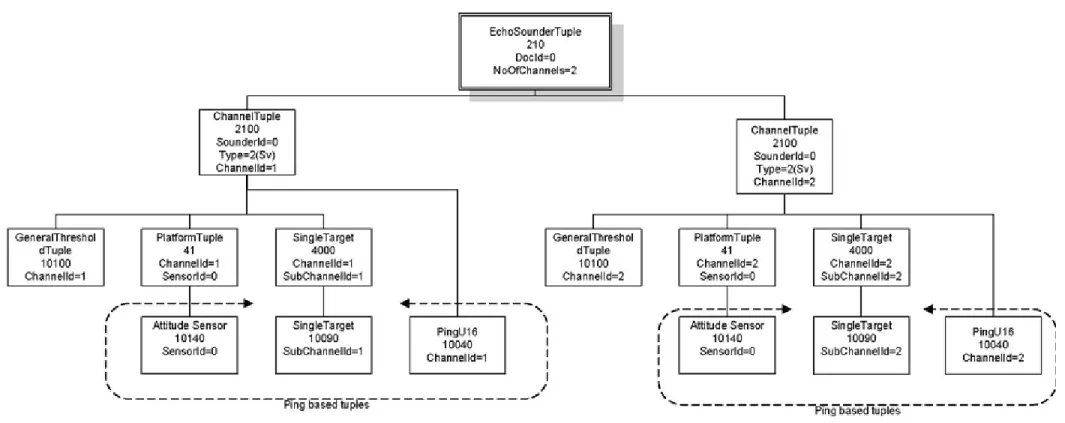
be related to each other in a hierarchical order. A “parent/child” relationship may exist
between tuples where common information is separated from particular information to prevent
redundancy, e.g. the Echosounder tuple, the Channel tuple, and the Ping tuple are
hierarchically related by parent/child relationships (Figure 1). Unique numbers, ranging from
0 to 65535, identify each tuple (Table 1). The PGHAC allocates these numbers to prevent any
“collisions” in tuple usage by various groups around the world and to agree on the definition
of the various information fields they contain.
There are many advantages to the tuple structure. According to Simard
et al
. (1997):
A file could have as many tuple types as needed to code the information in extenso or only a few tuple types to represent a minimum of information. Further, a data access program may search only for the tuple types of interest for a particular application. The format structure thus allows forward and backward compatibility in time. […] New versions of a program can always read the old tuple types; i.e. old files (backward compatibility). [The format structure] is therefore of great interest for the storage of raw fisheries hydroacoustic data at the acquisition step as well as for adding new information in subsequent processing steps, including [editing] commands or echo classifications resulting from various analyses. In this way, the raw data are kept unaltered and are always available to the scientist for new applications, while the data processing information that is required for proper interpretation remains attached to the file. The format is therefore useful for storing hydroacoustic data in large data banks as well as for data exchange at various levels of processing among the scientific community.Over the past five years, several new tuple types have been added to the
HAC
standard via the
PGHAC to accommodate new instruments and applications, demonstrating the forward
compatibility of the format structure.
4
Tuple syntax rules and definitions
All tuple types contain five required fields in the following order: (1) the tuple data size (total
length of the data fields), (2) the tuple type code, or file tag, (3) the data fields, (4) the tuple
attribute field (e.g. original tuple, edited tuple), and (5) the tuple backlink, which gives the
tuple size (i.e. 10 bytes longer than the tuple data size). Apart from these five required fields,
several additional rules and modifications affecting file structure and tuple content have been
ICES Cooperative Research Report No. 278 3 |
agreed upon by the PGHAC since version 1.0. They include (with the appropriate PGHAC
annual report referenced):
•
Allowable values in fields (ICES, 2001) – New values may be added to
individual fields at any revision. The current lists of options may be added to and
application code should be developed with the expectation of ANY permissible
values.
•
Multiple channel tuples (ICES, 2001) – More than one Channel tuple per
channel are allowed within a file.
•
Start and End of run tuples (ICES, 2001) – Start and End of run tuples are no
longer compulsory in a file, but should they occur in a single file, they should
always be paired. These tuple numbers have been removed from the basic tuple
list (see
HAC
Compliance
below).
•
Precision and “not applicable/not available/not known” data (ICES, 2001) –
LONG format data fields shall be used for continuous variables to allow a
four-decimal place precision and a larger range of permitted values. Where possible,
“not available/not known” will generally use the maximum permissible value for
unsigned fields and the minimum permissible value for signed fields unless
otherwise stated. Fields within a tuple that do not have applicable values for a
specific situation will generally use the second highest permissible value for “not
applicable” unless otherwise stated. For example, when translating data to one of
the generic tuples, several fields may require data or parameters that are not
applicable for the specific echosounder used.
•
Format of “char” (ICES, 2002) – Data type “char” shall be 7-bit only. A number
of formats are described in the literature for “char”, the earliest being 7-bit.
However, this does not allow for the coding of any non-English letters. An 8-bit
char does allow for these, and a variety of other symbols; however, there is no
single agreed international structure for 8-bit char, which could result in
confusion between countries, developers, and software. In the light of this, the
7-bit char is specified to avoid confusion.
•
Big and little endian formatted files (ICES, 2002) – Only “little endian” byte
order (PC platform) shall be used for a file to be
HAC
compliant (see below).
Originally, both big and little endian standards for byte order were permissible in
the format to enhance platform independence (PC versus UNIX). However, in
practice this was not necessary given that all known software developed for the
HAC
format at the time of the adoption of the format by ICES were on the PC
platform.
•
Variable vs. fixed-length tuples (ICES, 2002; 2003 and 2004) – Variable
lengths are allowed for any new tuple and the actual length shall be specified in
the Tuple Size field. The length of Remark fields will be of fixed dimension as
specified in the present document. This modification was proposed to allow new
fields to be added to existing tuples without major revision updates. Older
software would simply not read the extra fields. The size of the tuple would
remain in the first and last fields. Although variable lengths are desirable in
principle, several problems can occur, e.g. the PG had also decided in 2001 to
allow the use of variable length Remark fields. However, the combination
resulted in tuples that are not easily readable by most software. This had
generated some data problems with tuples 901 and 9001 (Generic echosounder
and channel) and also in tuple 2002 (the patch tuple for the EK500 channel). To
solve these ambiguities, it was decided to fix the Remark field lengths of tuples
901 and 9001 at 40 and 100 bytes, respectively, and at 20 bytes for tuple 2002.
However, given the possibility of older, different-sized fixed-length tuples and
newer, variable-length tuples, developers should always check tuple size when
coding. Therefore, the use of variable-length tuples should be restricted to the
4 | ICES Cooperative Research Report No. 278
c )
Where small modifications to existing fixed-length tuples are necessary,
“patch tuples” will be used (see below). The original tuple to which the
patch refers will indicate the presence of the patch using an entry in the
“attribute” field.
•
Negative values in angle data tuples (ICES, 2003) – “Two’s complement”
representation shall be used for storing all negative numbers. The format as
originally defined did not specify whether the “two’s complement” or the “sign +
magnitude” method should be used to store negative numbers. Although “two’s
complement” is the general standard in software, “two’s complement” had been
used by some developers and “sign + magnitude” by others in the angle data
tuples. The PG advises that programmers should implement code to allow for
both in angle data tuples.
•
Completion of remark fields (ICES, 2003) – All remark fields will be
terminated with a “null” character and the rest of the field will be left untouched.
•
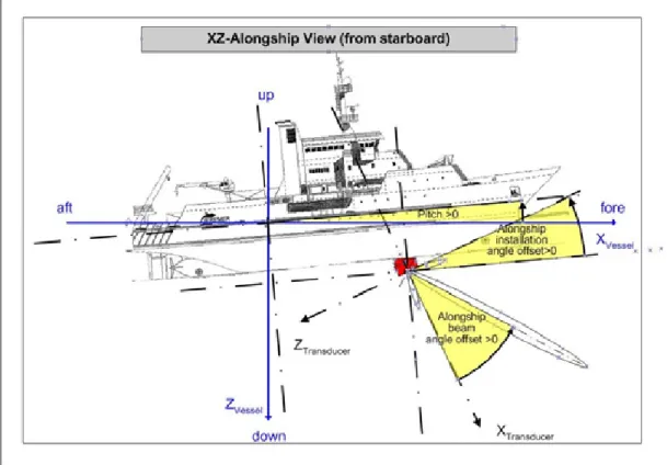
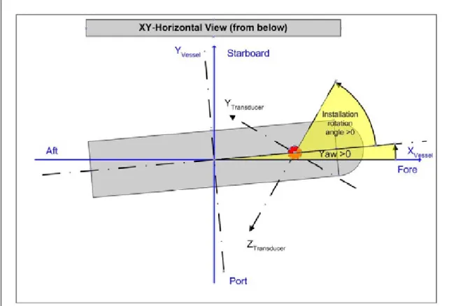
Angle coordinate variables – All the descriptions for angle coordinate variables
have been standardised (Annex 2) and are graphically presented in Figures 2–4
for clarity. An analysis of the treatment of angle coordinate variables showed
various inconsistencies between tuples. It was noted that although coordinate
systems for the various angle definitions (vessel motion, transducer installation
and beam) were all right-handed, they did not all have the same reference for the
x, y, and z direction. The modifications to the descriptions of angle variables
affect channel tuples (1000, 1001, 2000, 2001, 9001) and platform attitude tuples
(41, 42 10140, 10142).
5
Attribute codes
Attribute codes are used to label tuples according to certain qualitative characteristics
necessary for the proper interpretation of the data contained within them, e.g. tuple data
quality or state of processing. A grid of bit position codes has been developed to determine
permissible entries for the attribute field (Annex 3). This grid allows for the addition of new
attributes and combinations of attributes. Existing unique tuple attributes include:
•
original (code 0): The tuple is as produced from the acquisition software.
•
edited (bit 0 = 1): The basic concept of the
HAC
format is that data should be in
its rawest possible form and that all information necessary for post-processing
should be included within the file. However, there are many cases where
“semi-processed” data are required for the proper interpretation of the raw data. This is
most common when the data are to be exchanged between users of different
software. An example of this would be the redrawing of the seabed. An “edited”
value in the attribute field indicates that a tuple has been altered, however little.
This can act as a warning to the user. The onus is then on the user to find out
what has been changed.
•
temporary (bit 1 = 1): Temporary (unofficial) tuple numbers are assigned
specifically to allow developers to produce new software. They should not be
used in shipped software until approval and adoption is finalised by the PGHAC.
•
patched (bit 2 = 1): The tuple has been patched indicating that another tuple has
been created with additional information which must be referred to this tuple.
By assigning these unique attributes to bit positions, the attribute code can be determined from
Annex 3 by combining bit positions, e.g. to code a tuple as edited and patched, the bit
positions 0 and 2 will be set to 1, resulting in a code = 5. Negative codes could be used for
special cases.
ICES Cooperative Research Report No. 278 5 |
6
The
HAC
standard format tuple types
6.1
HAC
compliance
A data file is defined as
HAC
compliant if it contains tuples which conform to the
HAC
syntax rules, i.e. contains the minimum required
HAC
tuples using the exact tuple format
described in this document.
•
The minimum tuple types in a
HAC
file are: the
HAC
signature tuple, a Position
tuple, an Echosounder tuple, a Channel tuple, Ping tuples, a Threshold tuple, and
the End of file tuple.
Therefore a file (1) must start with the code 172 (=hexadecimal 0xAC, for ACoustics) stored
in a ULONG
2word in the
HAC
signature tuple, to identify the byte encoding mode of the
computer platform, and (2) must contain at least the seven minimum tuple types. The first
tuple in an
HAC
file must be the
HAC
signature tuple. The last tuple must be the End of file
tuple.
Tuples that have been examined and accepted by the PGHAC comprise the
HAC
standard
format and are described in Tables 2 – 31. Descriptions in these tables use a number of
conventional terms (Annex 4) and follow the above described syntax rules. To ease the
implementation of the
HAC
format by various software developers requiring the addition of
new tuples and to facilitate the work of the PGHAC, the tuple classes have been divided in
two groups. Any tuple to be added to the first group of basic tuple classes requires a thorough
examination and a unanimous agreement by the PGHAC.
•
The
basic tuple classes are: Position tuples, Platform attitude tuples,
Echosounder tuples, Channel tuples, Ping tuples, Threshold tuples,
Environmental tuples for sound speed profiles, End of file tuples, and the
HAC
signature tuple.
A second group includes the optional tuple classes that concern auxiliary information or a
secondary level of data analysis and completes the possible file content. Tuples within this
group need not be approved by the PGHAC.
•
The
optional tuple classes are: Mission and project tuples, Navigation tuples,
Event marker tuples, Edition tuples, Classification tuples, Environmental tuples
except sound speed profiles, Start of run and End of run tuples, Private tuples,
and Index tuples.
Since the initial definition of the
HAC
version 1.0, the following tuple numbers have been
added to the list of defined tuples and may or may not be in use. Those in bold are part of the
basic tuple types now accepted within the
HAC
standard:
•
30, 39, 41, 42,
210, 220, 300, 301, 901, 1001, 2001, 2002, 2100, 2200, 3000,
3001, 4000, 4010, 5000, 5001, 9001, 10011, 10039, 10090, 10119, 10140, 10142,
11000, 12000, 12005, 12010, 12050, 12051, 12052, 12053, 12100, 13000, 13500,
14000, 65397, 65406.
The list of the tuples defined and described within the
HAC
standard format (or in use by the
various groups in the acoustic community) as well as the reference to where these tuples were
originally described and modified is presented in Table 1. In addition to the new tuples which
have been added to the standard since the creation of the PGHAC, some discrepancies relative
to the original defined standard version 1.0 (Simard
et al
., 1997) were noted and have been
corrected for the present version 1.6.
6 | ICES Cooperative Research Report No. 278
6.2
HAC
compatibility
A software application is defined as
HAC
compatible if it can read and/or write, and use a
minimum number of commonly used basic tuples following the
HAC
syntax rules as outlined
in this document. These tuple numbers are:
•
20, 100, 200, 901, 1000, 2000, 2001, 2002,
9001, 10000, 10001, 10010, 10011,
10030, 10031, 10040, 10100, 65534, 65535.
7
Allocating tuple numbers and accepting new tuple definitions
The tuple type
field is 16 bits long (USHORT), allowing for the definition of 65536 different
tuple types (0 to 65535). The tuple type codes
of the
HAC
standard format are given in Table
1. Tuple numbers for the basic tuple classes are allocated temporarily to the applicants during
their definition and debugging period for a maximum of 14 months, after which time they are
retired if the committee has not accepted their description. Temporary tuple numbers are
assigned specifically to allow developers to produce new software. They should not be used in
shipped software until approval and adoption is finalised by the PGHAC. Unless stated
otherwise, new tuples will be considered provisional for two months after the current year’s
meeting to allow suggestions and objections to be made. Following that, and if no objections
are raised, they will be accepted. For new tuples in the optional tuple classes, the PGHAC
allocates tuple numbers at the request of the users, on presentation of a short justification and
objectives of the tuple by the applicant.
8
Description of basic tuple classes
8.1
Position tuple
This tuple type stores the geographic position of the transducer deployment platform. The data
collection rate of position data can be independent of the ping rate. [Reserved tuple type
codes: 20 – 29].
8.2
Platform attitude tuple
This tuple type stores the attitude (i.e. pitch, roll, heave, and yaw) of the transducer
deployment platform (i.e. ship, towed body, etc.). Tuples within this class have been designed
to store data from both fixed and dynamic platforms. Fixed platforms have the attitude sensor
at a fixed position relative to the transducer while dynamic platforms have a dynamic link
between the attitude sensor and the transducer. Information on platform attitude is stored in
either the platform attitude tuple class or the attitude sensor data tuple class. [Reserved tuple
type codes: 40 – 49, 10140 – 10149].
8.3
Echosounder tuple
An echosounder is defined as a group of channels with a common configuration. Therefore the
Echosounder tuple stores the information that is common to all channels of the group and is
machine-specific. If several machines of a similar type are operated simultaneously, they may
have the same Echosounder tuple. However, if several machines of different types are
operated simultaneously, then one Echosounder tuple per machine type will exist. [Reserved
tuple type codes: 100 – 999].
8.4
Channel tuple
The Channel tuple type is both machine- and channel-specific and is related to both the
hardware and software channels, including virtual channels (e.g. an echo-classification
ICES Cooperative Research Report No. 278 7 |
channel combining the information from a number of existing channels). This tuple type stores
the machine settings and calibration parameters specific to a given channel. This tuple type
may also include single-target detection information. In addition to the five fields common to
all tuples, this tuple type must also include the software channel identifier and the
echosounder
document identifier. [Reserved tuple type codes: 1000 – 9999].
8.5
Ping tuple
This tuple type stores a time-series of samples, either raw data or from processed information,
depending on the specific tuple description. Samples may be encoded with many formats and
several are described in this document, such as the U-32 for Sv or TS data or the
C-32-16-angles for split-beam phase angle data. The Ping tuple formats should be chosen according to
the desired resolution and their storage/recuperation efficiency. [Reserved tuple type codes:
10000 – 10099].
8.6
General threshold tuple
This tuple type stores the threshold used to filter samples during data acquisition. Algorithms
used to define the filter presently include a constant threshold or a time-varied threshold
(TVT). A given threshold applies to all pings collected subsequent to the time stamp of a
given Threshold tuple, unless superseded by a new Threshold tuple. [Reserved tuple type
codes: 10100 – 10109].
8.7
Environmental tuple (sound speed profile)
This tuple type stores the sound speed profile associated with the Echosounder tuple. If a fixed
sound speed (independent of depth) was used, the value can be stored in the Echosounder
tuple. [Reserved tuple type codes: 11000 – 11999].
8.8
End of file tuple
This tuple type identifies the end of the file and must be the last tuple in any tuple file. As
such, it can be used to provide an error check for truncated files. [Reserved tuple type codes:
65526 – 65534].
8.9
HAC
signature tuple
This tuple type stores the identification code confirming that the file is in the
HAC
standard
hydroacoustic data format and should be the first tuple of the file. A program should first read
this tuple to determine if it can interpret the file. [Reserved tuple type code: 65535].
9
Description of approved optional tuple classes
9.1
Private tuple
Temporary and private tuples as described in the
HAC
version 1.0 have been re-identified as
the Private tuple class only, since Temporary tuples exist outside of this category, namely
during the definition and debugging of the new tuples belonging to all other tuple classes
(ICES, 2000).
Private tuples are used only to store software information that does not belong to the other
tuple classes. However, this tuple class cannot be used to introduce proprietary formats inside
8 | ICES Cooperative Research Report No. 278
introduce new tuples must be followed (see Section 7 above). [Reserved tuple type codes:
65496 – 65505].
9.2
Temporary tuple
Temporary and provisional tuples are assigned specifically to encode information that is
needed for a fixed and relatively short period of time to allow developers to produce new
software. They should not be used in shipped software until approval and adoption is finalised
by the PGHAC. The definition of the fields of these tuples is left to the users but must respect
the
HAC
tuple syntax rules and required fields. [Reserved tuple type codes: assigned
according to tuple class (Table 1)].
10
Acknowledgements
The authors wish to acknowledge the contributions of all PGHAC members past and present,
as well as the participants of the original workshop held at the Maurice Lamontagne Institute
on 12–14 December 1995, all of whom have been instrumental in the development and
evolution of the
HAC
standard format. We particularly wish to thank Dr. Jon Preston who
through his own initiative managed to greatly clarify
the definitions of the various angle
variables and their coordinate systems. Also, we especially wish to thank the various acoustic
hardware and software developers involved in the definition and especially the
implementation of the
HAC
standard format in their products, which transforms our efforts
into very tangible results.
11
References
ICES. 2000. Report of the Working Group on Fisheries Acoustics Science and Technology.
Ijmuiden/Haarlem, Netherlands. ICES CM 2000/B:04.
ICES. 2001. Report of the Planning Group on the HAC Data Exchange Format. Seattle, USA.
ICES CM 2001/B:03.
ICES. 2002. Report of the Planning Group on the HAC Data Exchange Format. Sète, France.
ICES CM 2002/B:04.
ICES. 2003. Report of the Planning Group on the HAC Data Exchange Format. Bergen,
Norway. ICES CM 2003/B:03.
ICES. 2004. Report of the Planning Group on the HAC Data Exchange Format (PGHAC).
Gdynia, Poland. ICES CM 2004/B:04.
MacLennan, D. N., and Simmonds, E. J. 1992. Fisheries Acoustics. London, UK, Chapman
and Hall.
Simard, Y., McQuinn, I. H., Montmigny, M., Lang, C., Miller, D., Stevens, C., Wiggins, D.,
and Marchalot, C. 1997. Description of the HAC standard format for raw and edited
hydroacoustic data, version 1.0. Canadian Technical Report of Fisheries and Aquatic
Sciences: 65 p.
ICES Co oper ativ e Research Repo rt No. 278
12
Tuple Tables
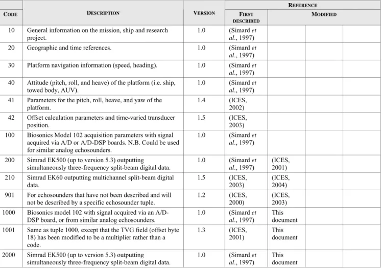
Table 1. List of tuples and tuple classes described in the
HAC
standard format for raw and edited hydroacoustic data and the reference documents where they were first described and subsequently modified (bold = basic tuple class).TUPLE CLASS TUPLE TYPE REFERENCE
NAME RANGE OF
CODES
NAME CODE DESCRIPTION VERSION FIRST
DESCRIBED
MODIFIED
Mission and project tuples
10–19 Mission and project 10 General information on the mission, ship and research project.
1.0 (Simard et al., 1997)
Position tuples 20–29 Position 20 Geographic and time references. 1.0 (Simard et
al., 1997)
Navigation tuples 30–39 Navigation 30 Platform navigation information (speed, heading). 1.0 (Simard et al., 1997)
Platform attitude tuples
40–49 Platform attitude 40 Attitude (pitch, roll, and heave) of the platform (i.e. ship, towed body, AUV).
1.0 (Simard et al., 1997) Platform attitude
parameters
41 Parameters for the pitch, roll, heave, and yaw of the platform. 1.4 (ICES, 2002) Dynamic platform position parameters
42 Offset calculation parameters and time-varied transducer position.
1.5 (ICES, 2003)
Echosounder tuples 100–999 Biosonics 102 100 Biosonics Model 102 acquisition parameters with signal acquired via A/D or A/D-DSP boards. N.B. Could be used for similar analog echosounders.
1.0 (Simard et al., 1997)
Simrad EK500 200 Simrad EK500 (up to version 5.3) outputting
simultaneously three-frequency split-beam digital data.
1.0 (Simard et al., 1997)
(ICES, 2001)
Simrad EK60 210 Simrad EK60 outputting multichannel split-beam digital
data. 1.5 (ICES, 2003) (ICES, 2004)
Generic
echosounder 901 For echosounders that have not been described and will not be described by a specific echosounder tuple. 1.2 (ICES, 2000) (ICES, 2003)
Channel tuples 1000–
9999
Biosonics 102 1000 Biosonics model 102 with signal acquired via an A/D-DSP board, or from similar analog echosounders.
1.0 (Simard et al., 1997)
This document Biosonics 102 1001 Same as tuple 1000, except that the TVG field (offset byte
18) has been modified to be a multiplier rather than a
1.3 (ICES, 2001)
This document
10 | ICES Co oper ativ e R es earc h R ep ort No. 2 78
TUPLE CLASS TUPLE TYPE REFERENCE
NAME RANGE OF
CODES
NAME CODE DESCRIPTION VERSION FIRST
DESCRIBED
MODIFIED
Simrad EK500b 2001 Same as tuple 2000, except that (1) surface blanking range has been added, and (2) the angle offsets and 3dB beamwidth fields have been expanded to 2 dec.
1.3 (ICES, 2001) (ICES, 2002) (ICES, 2003) This document Simrad EK500 channel patch
2002 Patches tuples 2000 and 2001 by specifying both EK500 transducer gains (Sv and TS) for a given transducer within a single channel tuple.
1.4 (ICES, 2002)
(ICES, 2003)
Simrad EK60 2100 Simrad EK60 outputting multichannel split-beam digital
data. 1.5 (ICES, 2003) (ICES, 2004) TS Parameters sub channel tuples 4000– 4009 Simrad EK500 single target sub-channel
4000 Split-beam detected single-target parameters. 1.4 (ICES, 2002)
Generic channel 9001 For echosounder channels that have not been described
and will not be described by a specific channel tuple.
1.2 (ICES, 2000) (ICES, 2003) This document Ping tuples 10000– 10099
Ping U-32 10000 A time-series of sample values encoded using an uncompressed 32-bit sample format. N.B. The detected bottom range is put to -1 when the bottom is not detected (i.e. is missing).
1.0 (Simard et al., 1997)
Ping
U-32-16-angles 10001 A time-series of encoded off-axis electrical angles from raw split-beam sample phase data. The sample sequence is encoded using an uncompressed 32-bit format while the encoding of the two angles, with an uncompressed 16-bit format, requires 32 more bits.
1.0 (Simard et al., 1997)
(ICES,
2001) (ICES, 2003) Ping C-32 10010 A time-series of sample values encoded using a
compressed 32-bit format for the zero series.
1.0 (Simard et al., 1997) (ICES, 2001) (ICES, 2003) Ping C-32-16-angles
10011 A time-series of compressed split-beam off-axis angle sample data encoded using a compressed 16-bit format.
1.3 (ICES, 2001) Ping U-16 10030 A time-series of samples using an uncompressed 16-bit
sample format.
1.0 (Simard et al., 1997)
Ping U-16-angles 10031 A time-series of encoded samples of split-beam off-axis phase angles. The sample sequence and the two angles are encoded using an uncompressed 16-bit format.
1.0 (Simard et al., 1997)
(ICES,
2003) Ping C-16 10040 A time-series of encoded samples using a compressed
16-bit format. 1.0 (Simard et al., 1997) (ICES, 2001) Ping CE-16 10050 A time-series of samples using a compressed and encoded
ICES Co oper ativ e Research Repo rt No. 278
TUPLE CLASS TUPLE TYPE REFERENCE
NAME RANGE OF
CODES
NAME CODE DESCRIPTION VERSION FIRST
DESCRIBED
MODIFIED
Split-beam detected single target 10090
Ping tuple for detected single target. 1.4 (ICES, 2002)
Threshold tuples 10100 –
10109
General threshold 10100 Constant and time-varied threshold (TVT) used during the acquisition to exclude samples. This threshold applies to the pings that are collected after the threshold setting time, until a subsequent threshold tuple updates the threshold information. 1.0 (Simard et al., 1997) (ICES, 2001) Event marker tuples 10110 –
10119 Event marker 10110 Time and text data used to mark events occurring during the acquisition or the edition at the user’s request. 1.0 (Simard al., 1997) et
Attitude sensor data tuples
10140 – 10149
Attitude sensor 10140 Pitch, roll, heave, and yaw of the transducer deployment platform. 1.4 (ICES, 2002) (ICES, 2003) This document Platform position 10142 Recording of the attitude and relative position of an
independent platform, e.g. a towed body or sounder mounted on a fishing net.
1.5 (ICES, 2003) This document Environmental tuples 11000 – 11999
STD profile 11000 To store environmental variables describing the conditions in the study area. One tuple could be defined for each sensor type, e.g. salinity, temperature, depth, sound speed, light, meteorological information, refreshed at their own rate. Multi-variable sensors (e.g. CTD: conductivity, temperature, depth) should have only one tuple. 1.0 (Simard et al., 1997) (ICES, 2004) This document Private tuples 65396 – 65405
Temporary tuple 1 65396 Temporary or testing tuples, or tuples specific to a particular or private application.
1.0 (Simard et al., 1997)
Organisation 65397 Contains a code identifying the organization to which this private tuple belongs, that controls the format of the data section of the tuple and that has the definition of the fields it contains. It has the advantage of preventing possible collisions in non-concerted use of the private tuple by various groups.
1.2 (ICES, 2000) Opening and closing
file tuples
65516 – 65525
Start of run 65516 To trace the file opening and appending steps (runs). New start of run tuples can be added each time data are appended to the file. These tuples are useful for selecting individual segments of a file such as acquisition runs.
1.0 (Simard et al., 1997)
12 | ICES Co oper ativ e R es earc h R ep ort No. 2 78
TUPLE CLASS TUPLE TYPE REFERENCE
NAME RANGE OF
CODES
NAME CODE DESCRIPTION VERSION FIRST
DESCRIBED
MODIFIED
End of file tuples 65526 –
65634
End of file 65534 Must be the last tuple of a HAC file. 1.0 (Simard et al., 1997) HAC signature
tuple
65635 HAC signature 65535 HAC file signature. 1.0 (Simard et al., 1997)
(ICES, 2000)
ICES Co oper ativ e Research Repo rt No. 278
Table 2. Position tuple (20).
OFFSET (BYTE)
FIELD LENGTH
(BYTES)
FORMAT CONTENT ENCODED
UNITS
LIMIT RANGE
0 Tuple size 4 ULONG Tuple data size: 26 bytes byte 26 4 Tuple type 2 USHORT Tuple type code: 20 unitless 20 6 Time fraction 2 USHORT Fraction of a second to add to the following CPU ANSI C time to get a time precision of 0.0001 s (Local
time at which the position was taken by the positioning system).
0.0001 s [0 – 6.5535 s] Practical range: [0 – 0.9999 s] 8 Time CPU ANSI C
Standard time
4 ULONG Local time at which the position was taken by the positioning system. ANSI C time given by the CPU clock, in seconds. Usually the CPU clock is set to local time. The difference with the GPS time gives the lag of the local time relative to the universal time.
s [0 – 4294967295 s] i.e.: [up to year 2106] 12 GPS time (GMT) 4 ULONG Universal time (GMT), given by the GPS, at which the position was taken by the positioning system.
Absolute time, in seconds, elapsed since midnight (00:00:00) 1 January 1970. s [0 – 4294967295 s] i.e.: [up to year 2106]
16 Positioning system 2 USHORT Positioning system used: 0 = Loran C
1 = GPS 2 = DGPS
Other systems to be coded.
unitless [0 – 65535] Presently: [0; 1; 2] 18 Space 2 USHORT Space to allow the next field to be aligned on an address that is a multiple of 4. unitless 0
20 Latitude 4 LONG Latitude, in degrees. Negative values are in the southern hemisphere. 0.000001 deg precision: ~ 2 cm [−214.7483648 – 214.7483647 deg] Practical range: [−90.000000 – 90.000000 deg] 24 Longitude 4 LONG Longitude, in degrees. Negative values are western coordinates. 0.000001
deg precision: ~ 2 cm [−214.7483648 – 214.7483647 deg] Practical range: [−180.000000 – 180.000000 deg] 28 Tuple attribute 4 LONG Attribute of the tuple according to Annex 3.
0 = original 1 = edited 2 = temporary 3 = temporary + edited 4 = patched unitless [−2147483648 – 2147483647]
14 | ICES Co oper ativ e R es earc h R ep ort No. 2 78
Table 3. Platform attitude parameters tuple (41).
OFFSET (BYTE)
FIELD LENGTH
(BYTES)
FORMAT CONTENT ENCODED
UNITS
LIMIT RANGE
0 Tuple size 4 ULONG Tuple data size: 54 bytes byte 54 4 Tuple type 2 USHORT Tuple type code: 41 unitless 41 6 Time fraction 2 USHORT Fraction of a second to add to the following CPU ANSI C time to get a time precision of 0.0001 s (Local
time at which the platform attitude reading was taken).
0.0001 s [0 – 6.5535 s] Practical range: [0 – 0.9999 s] 8 Time CPU ANSI C
Standard time
4 ULONG Local time at which the platform attitude reading was taken. ANSI C time given by the CPU clock, in seconds. Usually the CPU clock is set to local time.
s [[0 – 4294967295 s ] i.e.: [up to year 2106] 12 Dependent attitude
sensor identifier
2 USHORT Unique identifier of the dependent attitude sensor. unitless [0 – 65535] 14 Transceiver channel
number
2 USHORT Transceiver channel number from the parent channel tuple to which these parameters refer. unitless [0 – 65535] 16 Platform type 2 USHORT The platform type in which the attitude sensor is installed:
0 = ship 1 = towed body 1 2 = towed body 2 3 = AUV 4 = ROV 5 = pelagic trawl 6 = bottom trawl unitless [0 – 65535] Presently: [0; 1; 2; 3; 4; 5; 6]
18 Alongship offset 2 SHORT Distance between the center of the transducer and the reference point of the attitude sensor in the fore and aft direction (X). Positive values are on the foreword side of the reference point of the attitude sensor.
0.01 m [−327.68 – 327.67 m] 20 Athwartship offset 2 SHORT Distance between the center of the transducer and the reference point of the attitude sensor in the
starboard and port direction (Y). Positive values are on the port side of the reference point of the attitude sensor.
0.01 m [−327.68 – 327.67 m] 22 Elevation offset 2 SHORT Distance between the transducer face and the reference point of the attitude sensor in the vertical
direction (Z). Positive values are below the reference point of the attitude sensor.
0.01 m [−327.68 – 327.67 m] 24 Remarks 30 CHAR Character string comment, up to 30 characters. This field could be used to store the sensor type and
serial number. ASCII char. 30 characters 54 Space 2 USHORT Space to allow the next field to be aligned on an address that is a multiple of 4. unitless 0
ICES Co oper ativ e Research Repo rt No. 278 OFFSET (BYTE) FIELD LENGTH (BYTES)
FORMAT CONTENT ENCODED
UNITS
LIMIT RANGE
56 Tuple attribute 4 LONG Attribute of the tuple according to Annex 3. 0 = original
1
= edited 2 = temporary 3 = temporary + edited 4 = patched 5 = patched + edited … unitless [−2147483648 – 2147483647]16 | ICES Co oper ativ e R es earc h R ep ort No. 2 78
Table 4. Dynamic platform position parameters tuple (42).
OFFSET (BYTE)
FIELD LENGTH
(BYTES)
FORMAT CONTENT ENCODED
UNITS
LIMIT RANGE
0 Tuple size 4 ULONG Tuple data size: 62 bytes byte 62 4 Tuple type 2 USHORT Tuple type code: 42. unitless 42 6 Time fraction 2 USHORT Fraction of a second to add to the following CPU ANSI C time to get a time precision of 0.0001 s
(Local time at which the platform position reading was taken).
0.0001 s [0 – 6.5535 s] Practical range: [0 – 0.9999 s] 8 Time CPU ANSI C
Standard time
4 ULONG Local time at which the platform position was taken. ANSI C time given by the CPU clock, in seconds. Usually the CPU clock is set to local time.
s [0 – 4294967295 s ] i.e.: [up to year 2106] 12 Dependent distance
sensor identifier
2 USHORT Unique identifier of the dependent sensor to which all distances (X and Y in tuple 10142) are referenced.
unitless [0 - 65535 ] 14 Dependent depth sensor
identifier
2 USHORT Unique identifier of the dependent sensor to which all depths (Z in tuple 10142) are referenced. unitless [0 – 65535 ] 16 Transceiver channel
identifier 2 USHORT Transceiver channel identifier from the parent channel tuple to which these parameters refer. unitless [0 - 65535 ] 18 Platform type 2 USHORT Platform type in which the transducer/echosounder is installed:
0 = ship 1 = towed body 1 2 = towed body 2 3 = AUV 4 = ROV 5 = Pelagic trawl 6 = Bottom trawl unitless [0 – 65535 ] Presently: [0, 1, 2, 3, 4, 5, 6]
20 Distance sensor type 2 USHORT Distance sensor type: 0 = acoustic positioning 1 = cable length
2 = combining cable length and angle measurement 3 = other
unitless [0 – 65535 ] Presently: [0, 1, 2, 3] 22 Depth sensor type 2 USHORT Position sensor type:
0 = acoustic positioning (phase measurement) 1 = pressure sensor
2 = acoustic depth measurement
3 = acoustic bottom altitude measurement (including pinger) 4 = other
unitless [0 – 65535 ] Presently: [0, 1, 2, 3, 4] 24 Alongship offset 2 SHORT Distance between the position sensor and the attitude sensor in the fore and aft direction (X). Positive
values are on the foreward side of the reference point of the attitude sensor.
0.01 m [−327.68 – 327.67 m] 26 Athwartship offset 2 SHORT Distance between the position sensor and the attitude sensor in the starboard and port direction (Y). 0.01 m [−327.68 – 327.67 m]
ICES Co oper ativ e Research Repo rt No. 278 OFFSET (BYTE) FIELD LENGTH (BYTES)
FORMAT CONTENT ENCODED
UNITS
LIMIT RANGE
Positive values are on the starboard side of the reference point of the attitude sensor.
28 Vertical offset 2 SHORT Distance between the sea surface and the attitude sensor in the vertical direction (Z). Positive values
are below the surface. 0.01 m [−327.68 – 327.67 m] 30 Space 2 USHORT Space to allow the next field to be aligned on an address that is a multiple of 4. unitless 0
32 Remarks 30 CHAR Character string comment, up to 30 characters. This field could be used to store the sensor type and
serial number. ASCII char. 30 characters 62 Space 2 USHORT Space to allow the next field to be aligned on an address that is a multiple of 4. unitless 0
64 Tuple attribute 4 LONG Attribute of the tuple according to Annex 3. 0 = original 1 = edited 2 = temporary 3 = temporary + edited 4 = patched 5 = patched + edited … unitless [−2147483648 – 2147483647]
18 | ICES Co oper ativ e R es earc h R ep ort No. 2 78
Table 5. Biosonics Model 102 Echosounder tuple (100).
OFFSET (BYTE)
FIELD LENGTH
(BYTES)
FORMAT CONTENT ENCODED
UNITS
LIMIT RANGE
0 Tuple size 4 ULONG Tuple data size: 62 bytes byte 62 4 Tuple type 2 USHORT Tuple type code: 100. This is the tuple type code for the Biosonics Model 102 echosounder. (Tuples 100 – 199
are reserved for Biosonics echosounders). unitless 100 6 Number of
software channels
2 USHORT Number of software channels associated with this echosounder. unitless [1 – 65535] 8 Echosounder
document identifier
4 ULONG Unique identification number for the echosounder document (i.e. the group of channels). The channels are tied
to the echosounder by the echosounder document identifier, which is repeated in the channel tuples. unitless [0 – 4294967295] 12 Sound speed 2 USHORT Speed of sound. Note: Sound speed and sound speed profiles could also be computed from environmental
tuples. 0.0 = profile used 0.1 m s-1 [0 – 6553.5 m s-1] In water: [1450.0 – 1550.0 m s-1]
14 Ping interval 2 USHORT Interval between 2 pings. In the multifrequency mode of the Biosonics 102, the acoustic frequency is alternating every ping.
0.01 s [0 – 655.35 s] i.e.: [up to 10.92 min] 16 Transmitter attenuation setting
2 SHORT The attenuation factor of the transmitter corresponding to the echosounder setting. This setting corresponds to a
given source level recorded in the source level field of the channel tuple. 0.1 dB [dB] −3276.8 – 3276.7 Biosonics 102 options:
[−13, −10, −6, −3, 0 dB]
18 Multiplexing
mode 2 USHORT The operating transmitter mode of the echosounder. 0 = F1/X1 (frequency 1 on transducer 1) 1 = F2/X2 (frequency 2 on transducer 2)
2 = Ext. (transmitter and transducer controlled externally) 3 = F1/F2 multiplexed F1/X1 and F2/X2 4 = F1/X2 (frequency 1 on transducer 2) 5 = F2/X1 (frequency 2 on transducer 1) unitless [0 – 65535] Biosonics 102 options: [0, 1, 2, 3, 4, 5] 20 Blanking at TVG max. range
2 USHORT The gain operating mode after the TVG max. range, from the blank at range switch.
0 = normal mode, the gain is maintained constant at the value reached at the TVG max. range. 1 = blank at range mode: the gain drops to zero at the TVG max. range.
unitless [0 – 65535] Biosonics 102 options: [0, 1]
ICES Co oper ativ e Research Repo rt No. 278 OFFSET (BYTE) FIELD LENGTH (BYTES)
FORMAT CONTENT ENCODED
UNITS
LIMIT RANGE
22 TVG max. range 2 USHORT The range up to which the TVG is applied. Biosonics 102 echosounders normally apply TVG over the following two decade ranges: 1.25 – 125 m, 2.5 – 250 m, 5 – 500 m or 10 – 999.9 m, depending on hardware setting. TVG is computed from the transducer face and applied from the min. range up to the max. range. This max. range can, however, be limited to a smaller range by a range switch, whose setting would give the value of the present field. After this TVG max. range the gain is either maintained constant at the value reached at this range or dropped to zero if the TVG blank at range switch is on.
0.1 m [0 – 6553.5 m] Biosonics 102 options: [0 – 999.9 m] 24 Blanking up to range
2 USHORT Blanking range up to which the receiver output is blanked to zero. It is often set to the TVG min. range of either, 1.25, 2.5, 5.0 or 10.0 m. A blanking range of 0 sets the TVG off.
0.1 m [0 – 6553.5 m] Biosonics 102 options: [0 – 999.9 m] 26 Calibrator signal 2 SHORT Calibrator signal sent to the receiver from the echosounder setting:
0 = off, no calibrator signal is sent (This is the usual setting when echosounding).
dB [−32768 – 32767 dB] Biosonics 102 options:
[−40, −20, 0, 20 dB] 28 Calibrator mode 2 USHORT Type of sound wave sent to the receiver:
0 = pulse, a pulse repeated at the interval given by the separation field below 1 = constant wave unitless [0 – 65535] Biosonics 102 options: [0, 1] 30 Calibrator separator
2 USHORT Separation distance for the calibrator sound pulse when this mode is selected (previous field). 0.1 m [0 – 6553.5 m] Biosonics 102 options: [0 – 99.9 m] 32 Remarks 30 CHAR Character string comment, up to 30 characters. This field could be used to store the echosounder serial number. ASCII
char.
30 characters 62 Space 2 USHORT Space to allow the next field to be aligned on an address that is a multiple of 4. unitless 0
64 Tuple attribute 4 LONG Attribute of the tuple according to Annex 3. 0 = original 1 = edited 2 = temporary 3 = temporary + edited 4 = patched 5 = patched + edited … unitless [−2147483648 – 2147483647]
20 | ICES Co oper ativ e R es earc h R ep ort No. 2 78
Table 6. Simrad EK500 Echosounder tuple (200).
OFFSET (BYTE)
FIELD LENGTH
(BYTES)
FORMAT CONTENT ENCODED
UNITS
LIMIT RANGE
0 Tuple size 4 ULONG Tuple data size: 70 bytes byte 70 4 Tuple type 2 USHORT Tuple type code: 200. This is the tuple type code for the Simrad EK500. (Tuples 200 – 299 are
reserved for Simrad echosounders). unitless 200 6 Number of software
channels 2 USHORT Number of software channels associated with this echosounder. unitless [1 – 65535] 8 Echosounder document
identifier
4 ULONG Unique identification number for the echosounder document (i.e. the group of channels). unitless [0 – 4294967295] 12 Sound speed 2 USHORT Speed of sound. Note: Sound speed and sound speed profiles could also be computed from
environmental tuples. 0.0 = profile used
0.1 m s-1 [0 – 6553.5 m s-1]
In water:
[1450.0 m s-1 – 1550.0 m s-1] 14 Ping mode 2 USHORT Ping mode:
1 = normal
2 = external (trigged from an external source) 3 = synchronized
unitless [0 – 65535] EK500 options: [0, 1, 2, 3] 16 Ping interval 2 USHORT Interval between 2 pings.
0.00 = not known or variable
0.01 s [0 – 655.35 s] i.e.: [up to 10.92 min] 18 Transmit power 2 USHORT Nominal output power:
0 = normal
1 = reduced (The transmit power is reduced from its nominal value by 20 dB on all transceiver channels).
unitless [0 – 65535] EK500 options: [0 or 1] 20 Noise margin 2 USHORT The margin to add to the system noise to threshold out the samples. dB [0 – 65535 dB]
EK500 options: [ 0 – 40 dB] 22 Sample range 2 USHORT Range for the sample angle and sample power telegrams. m [0 m – 65535 m]
EK500 options: [0 – 10000] 24 Super layer: Type 2 USHORT Super layer type:
0 = off 1 = surface 2 = bottom
3 = pelagic (This layer type must be chosen to get values from the Ethernet port when the bottom is not found [e.g. for passive acoustics])
unitless [0 – 65535] EK500 options: [0, 1, 2, 3] 26 Super layer: Number 2 USHORT Layer number for the super layer. unitless [0 – 65535]
EK500 options: [1– 10] 28 Super layer: Range 2 USHORT Super layer thickness. 0.1 m [0 – 6553.5 m]
ICES Co oper ativ e Research Repo rt No. 278 OFFSET (BYTE) FIELD LENGTH (BYTES)
FORMAT CONTENT ENCODED
UNITS
LIMIT RANGE
EK500 options: [0 – 1000.0 m] 30 Super layer: Start 4 LONG Beginning depth of super layer relative to the transducer depth or the detected bottom. Negative
values indicate starting depth below the reference depth.
0.1 m [−214748364.8 – 214748364.7 m] EK500 options: [−10.0 – 9999.9 m] 34 Super layer: Margin
2 USHORT Margin relative to the transducer depth or the bottom, to stop the super layer. 0.1 m [0 – 6553.5 m] EK500 options: [0 – 10.0 m] 36 Super layer:
Sv threshold
2 SHORT Threshold to accept Sv samples. dB [−32768 – 32767 dB] EK500 options: [−100 – 0 dB] 38 EK500 version 4 ULONG EK500 version number. unitless [0 – 42949672.95]
Present range: [0 – 5.39] 42 Remarks 30 CHAR Character string comment, up to 30 characters. This field could be used to store the echosounder
serial number. ASCII char. 30 characters 72 Tuple attribute 4 LONG Attribute of the tuple according to Annex 3:
0 = original 1 = edited 2 = temporary 3 = temporary + edited 4 = patched 5 = patched + edited … unitless [−2147483648 – 2147483647]
22 | ICES Co oper ativ e R es earc h R ep ort No. 2 78
Table 7. Simrad EK 60 Echosounder tuple (210).
OFFSET (BYTE)
FIELD LENGTH
(BYTES)
FORMAT CONTENT ENCODED
UNITS
LIMIT RANGE
0 Tuple size 4 ULONG Tuple data size: 58 bytes byte 58 4 Tuple type 2 USHORT Tuple type code: 210. Tuple type code for the Simrad EK 60. unitless 210 6 Number of software channels 2 USHORT Number of software channels associated with this sounder. unitless [1 – 65535] 8 Echo sounder document
identifier 4 ULONG Unique identification number for the echosounder document (i.e. the group of channels). unitless [0 – 4294967295] 12 Sound speed 2 USHORT Mean speed of sound.
0.0 = Profile used 0.1 ms
-1 [0 – 6553.5 ms-1]
EK 60 range: [1400.0 – 1700.0 ms-1]
14 Ping mode 2 USHORT Ping mode. 1 = normal 2 = external
unitless [0 – 65535] 16 Ping interval 2 USHORT Interval between 2 pings.
0.00 = not known or variable 0.01 s [0 – 655.35 s] 18 Space 2 USHORT Space to allow the next field to be aligned on an address that is a multiple of 4. unitless
20 Remarks 40 CHAR Software version (example: “1.2.34.5678”) ASCII 40 characters 60 Tuple attribute 4 LONG Attribute of the tuple according to Annex 3.
0 = original 1 = edited 2 = temporary 3 = temporary + edited 4 = patched 5 = patched + edited … unitless [−2147483648 – 2147483647]
ICES Co oper ativ e Research Repo rt No. 278
Table 8. Generic Echosounder tuple (901) used with echosounders for which no Echosounder tuple has been described in the
HAC
standard data format.OFFSET (BYTE)
FIELD LENGTH
(BYTES)
FORMAT CONTENT ENCODED
UNITS
LIMIT RANGE
0 Tuple size 4 ULONG Tuple data size: 118 bytes byte 118 4 Tuple type 2 USHORT Tuple type code: 901. This is the tuple type code for the generic echosounder. unitless 901 6 Number of software
channels
2 USHORT Number of software channels associated with this echosounder. unitless [1 – 65535] 8 Echosounder
document identifier
4 ULONG Unique identification number for the echosounder document (i.e. the group of channels). The channels are tied to the echosounder by the echosounder document identifier, which is repeated in the channel tuples.
unitless [0 – 4294967295 ] 12 Sound speed 2 USHORT Mean sound speed used in the sounder. Mean sound speed should be calculated over the range of the
sample data. 0.0 = profile used
0.1 m s-1 [0 – 6553.5 m s-1]
In water:
[1450.0–1550.0 m s-1]
14 Ping interval 2 USHORT Interval between 2 pings. If a multiplexing echosounder triggers the various transducers in sequence, the recorded ping interval is the master trigger interval.
0 = not known or variable (the interval can be obtained from the time difference between pings)
0.01 s [0 – 655.35 s] i.e.: [up to 10.92 min] 16 Trigger mode 2 USHORT The source characteristics of the trigger.
1 = normal 2 = external 3 = synchronized unitless [0 – 65535] Presently: [0, 1, 2, 3] 18 Space 2 USHORT Space to allow the next field to be aligned on an address that is a multiple of 4. unitless 0 20 Remarks 100 CHAR Character string comment. This field could be used to store the echosounder brand, its properties and the
serial number.
ASCII char.
100 characters 120 Tuple attribute 4 LONG Attribute of the tuple according to Annex 3.
0 = original 1 = edited 2 = temporary 3 = temporary + edited 4 = patched 5 = patched + edited … unitless [−2147483648 – 2147483647]
24 | ICES Co oper ativ e R es earc h R ep ort No. 2 78
Table 9. Biosonics Model 102 Channel tuple (1000).
OFFSET (BYTE)
FIELD LENGTH
(BYTES)
FORMAT CONTENT ENCODED
UNITS
LIMIT RANGE
0 Tuple size 4 ULONG Tuple data size: 98 bytes. byte 98 4 Tuple type 2 USHORT Tuple type code: 1000. This is the tuple type code for the Biosonics 102. unitless 1000 6 Software channel
identifier 2 USHORT Unique identifier for this software data channel This identifier must be unique for the whole file in order to associate the pings to their proper parent channel. Note: This is not the hardware channel number. unitless [0 – 65535] 8 Echosounder document
identifier 4 ULONG Identification number for the parent echosounder document (i.e. the group of channels) to which this data channel belongs. It is the echosounder document identifier field of the echosounder tuple. unitless [0 – 4294967295] 12 Sampling rate 4 ULONG Digitization rate for this channel. sample s-1 [0 – 4294967295 sample
s-1]
16 Type of data sample 2 USHORT Type of data sample: 0 = volts
1 = Sv (Scattering volume in dB)
2 = TS (Target strength of single targets in dB) 3 = Offaxis mechanical angles of single targets Others to be defined.
unitless [0 – 65535]
Biosonics 102 options: [0, 1, 2, 3]
18 Time varied gain mode 2 USHORT Time-varied gain (TVG) applied for this channel: 0 = 20 log R TVG
1 = 40 log R TVG
Note: This TVG is applied from a min. range up to the TVG max. range field of the echosounder tuple. When this TVG max. range is null or smaller than the blanking up to range, or the blanking up to range is set to zero, no TVG is applied. See pertinent fields in Biosonics Model 102 Echosounder tuple.
unitless [0 – 65535]
Biosonics 102 options: [0, 1]
20 Transceiver channel
number 2 USHORT Hardware channel number from which the data are coming. It is convenient to use the same channel numbers as from the echosounder. The Biosonics 102 has the narrow-beam signal on channel 1, the wide-beam signal on channel 2, and the simultaneous 20 log R narrow-beam on channel 3. When the 40 log R TVG switch is on, channels 1 and 2 are the 40 log R signals. Note: This field is not the software channel number.
unitless [0 – 65535]
CH1 DSP-A/D options: [1, 2, 3]
22 Space 2 USHORT Space to allow the next field to be aligned on an address that is a multiple of 4. unitless 0
24 Acoustic frequency 4 ULONG Acoustic frequency. Hz [0 – 4294967295 Hz] Fisheries acoustics range:
[100 – 1000000 Hz] 28 Installation depth of
transducer
4 ULONG Installation depth of transducer relative to the sea surface. 0.01 m [0 – 42949672.95 m] Working range: [0 – 999.99 m] 32 Alongship angle offset
of the transducer face 2 SHORT Mechanical offset angle of the transducer face relative to the horizontal in the alongship plane of the attitude sensor coordinate system (XY). Positive angles indicate the foreward side is above the horizontal.
0.1 deg [−3276.8 – 3276.7 deg] Working range: [−360.0 – 360.0 deg]