Introducing bus systems
Intelligent bus systems make buildings more cost-effec-tive to operate, safer, more flexible, more energy-effi-cient and – above all – more comfortable and conveni-ent. The KNX standard oc-cupies a large share of the market for building automa-tion systems.
Past, present and future
People live differently from how they did just a decade or two ago. We get money from cash dispensers, buy and sell goods and services over the in-ternet, phone friends all over the world from our mobile phones, and start to moan if an MMS or e-mail takes more than 5 minutes to reach a des-tination in the USA. In our cars we are guided around by sat navs, and we lock and unlock the doors remotely without a key. The interior light goes on the moment we step inside, then after a while slowly dims down again. In short, for quite some time we have been en-joying cutting-edge develop-ments in the areas of com-munication, entertainment and automotive technology. If we look at how technolo-gy in buildings has developed over the same period, it’s a very different story. We still open our flat doors with con-ventional keys; and if we can’t find our keys fast enough, the staircase light timer switch-es the lights off and plungswitch-es us into darkness. True, while we’re out working all day, the heating automatically keeps our homes at a pleasant tem-perature – but it doesn’t no-tice whether we left the living room window open when we went out. Only the electrici-ty meter, ticking away quiet-ly in a switch cabinet, notices
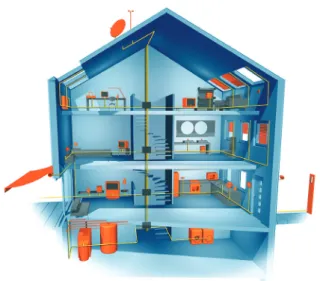
that. Before going away for the weekend, it is wise to turn down the temperature in our hot water tanks and to turn off all those electrical appliances on standby. But no one actu-ally does – at least, not relia-bly. It takes too long. Time to do some catching up So electrical installations in buildings have some substan-tial catching up to do. Net-worked sensors and actuators have long since been a standard feature of motor cars; build-ings, on the other hand, are lagging some way behind. A change of mindset is needed, not least because of the long service life of an electrical in-stallation. Today’s new build-ings will have to adapt to nu-merous changes over the next few decades. Now, more than ever, buildings need to be flex-ible and capable of accommo-dating networked building ser-vices. In technical terms, all of this is already entirely feasi-ble (Fig. 1).
Figure 1. “Smart” houses that adapt to users’ needs? It sounds like something from a sci-fi novel, but it is already a reality. Intelligent buildings incorporating networks of sophisticated devices that control the building as needed already exist, and are making life easier for their occupants on a day-to-day basis.
More networking
The key to making a building “intelligent” is to equip it with networked sensors and actua-tors. There are several differ-ent ways of doing this:
Conventional methods
The immediately obvious so-lution is to employ a star to-pology, i.e. an arrangement where every socket outlet circuit, ceiling or wall out-let, and light switch is linked by its own (ideally five-core) NYM cable to a central dis-tribution board in which the logical relationships are creat-ed by contactors, switch re-lays, and a programmable logic controller (PLC). This works well in reasonably small dwell-ings. However, the size of the house only needs to increase by a fairly small amount before the extent of the wiring work and size of the power distribu-tion boards required becomes excessive. In a star topology, adding to or extending the sys-tem is also very time-consum-ing in terms of installation and programming.
Bus technology
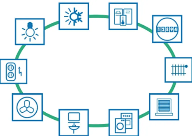
A far better solution is to link all sensors and actuators in the building with a “data cable”, and enable them to share infor-mation with each other (Fig. 2). Each device can then commu-nicate with every other device, for example: a light switch can “talk” to a dimmer and tell it how bright to set the ceiling light; a motion sensor can tell the actuator for the corridor lighting that someone has en-tered the corridor, or tell the room thermostat that there is no one in the room any more, so it can turn down the tem-perature. The following are examples of sensors that can send information to the bus: • Light switches
• Dimmer switches • Motion sensors
• Presence detectors (which can detect whether there is a person in a room even if they are not moving) • Window and door contacts
(for security and heating control)
• Doorbell buttons for front doors
• Water, gas, electricity and heat meters
• Overvoltage sensors • Temperature sensors for
in-door and outin-door air • Temperature sensors in
heat-ing and hot water circuits • Modules for preselecting
room temperature setpoints • Brightness sensors for in-doors and outin-doors, e.g. for constant lighting control • Wind sensors for
control-ling blinds
• Fault and system status mes-sages for white goods (wash-ing machine, clothes dryer, dishwasher, cooker, etc.) • Leak sensors, e.g. in laundry
room
• Level measurements e.g. for rain water tank, oil tank, wood pellet store
Figure 2. A bus system is a system of sensors and actuators joined together by a “bus cable”.
• Radio receivers for door locks
• Receivers for infrared re-mote controls
• Fingerprint modules and card readers for access control The following are examples of actuators that can be con-trolled via the bus:
• Relays for switching room lights on and off
• Dimmers and DALI-gate-ways
• Electric thermostatic radia-tor valves
• Temperature displays • Drive mechanisms for
awn-ings, blinds, curtains and ga-rage doors
• Drive mechanisms for win-dows
• Circulator pumps for heat-ing systems
• Valve control systems, e.g. for solar thermal installations • Alarms (lights and buzzers) • Information displays and
in-dicator LEDs
• Relays for making and break-ing socket outlet circuits (standby cut-off)
• Well pumps
• Air conditioning systems • Ventilation systems (toilet/
bathroom extractor fans, controlled ventilation for living areas)
• Control of washing machine, dryer, dishwasher
• Consumer electronics • Trigger signals for alarm
sys-tems
• Telephone systems • Electric door openers and
door locking systems Examples of functional mod-ules (may be self-contained or integrated in devices): • Room temperature
control-lers
• Timer functions
• Freely-programmable logic modules
• PLCs with KNX interface • Constant lighting control
modules
• Alarming and alerting • Telephone switchboards
connected to the bus • Media control • Heating control • Pump control
• Presence simulation • Displays and user interfaces • Modules for connecting bus
with telephone
• Modules for automatically sending warning messages by text
• Modules for accessing build-ing data from outside via the internet or a phone Why KNX?
There are several bus tech-nologies on the market. All of them are beneficial and appropriate for certain are-as of application. But no oth-er bus system is supported by as many different manufactur-ers as KNX. This is because: • All strong brands in the build-ing installation sector are pushing KNX technology • KNX was developed
spe-cifically to meet the needs of electrical installations in buildings
• KNX devices are installed, programmed and parame-terised by fully qualified sys-tem integrators
• KNX is well-established and can accommodate a huge range of functions
• There are several thou-sand KNX-certified prod-uct groups available, cover-ing every conceivable field of application
• KNX products are tested for conformity by an independ-ent third party test labora-tories
• KNX products are compat-ible with products from all manufacturers (interwork-ing)
• End customers benefit from an extensive network of spe-cialist tradesmen with sol-id KNX skills accredited by KNX-certified training cen-tres
• The PC software ETS can be used to plan, design and commission installations of KNX-certified products from any manufacturer • KNX supports all
communi-cation media: TP (based on a standalone 2-wire bus ca-ble), PL (Powerline), RF (Ra-dio Frequency), and IP/Eth-ernet/WLAN
• KNX is standardised in Eu-rope, the USA, China and internationally, through e.g. CENELEC EN 50090 rope), CEN 13321-1/2 (Eu-rope), ISO/IEC 14543-3 (International), GB/T 20965 (China), and ANSI/ASHRAE 135 (USA). More than 350 KNX members in 37 coun-tries manufacture products according to the KNX stand-ard. Because the technology is standardised, KNX prod-ucts are all mutually com-patible and KNX installa-tions can be easily modified or extended at a later stage.
Do bus installations make sense financially? This is one of the first ques-tions that building owners and tradespeople ask when con-sidering bus technology. As so often – it depends. At first glance, bus systems appear more expensive than conven-tional installations. But appear-ances can be very deceptive! What need to be considered are the benefits offered by a system over its entire service life. Depending on the build-ing type, the followbuild-ing may be compelling arguments for choosing a bus system:
Figure 3. A study conducted by the Institute for Building and Energy Systems at Biberach University of Applied Sciences, entitled “The potential offered by modern electrical installations for saving energy”, has revealed that the use of a KNX-based, networked home and building control system can reduce energy consumption by as muchas 50 %.
Individual
Room
control
Automation of Heating Automation
of Sun shading Automation
of Lighting Automation of Ventilation 80 70 60 50 40 30 20 10
Reduced energy consumption in %
50
40 45
80
The KNX bus system
Intelligent bus systems make buildings more cost-effective to operate, safer, and more flexible. The KNX standard occupies a large share of the market for building automa-tion systems.
Where does the name KNX come from? The KNX building automation system was originally known as the European Installation Bus (EIB), and was developed and marketed by the EIB Associ-ation (EIBA). In 1999, EIBA, Batibus Club International (BCI, France) and the Euro-pean Home Systems Asso-ciation (EHSA, Netherlands) amalgamated, the name KNX was adopted, and the Brus-sels-based KNX Association was set up. The technology used in modern KNX devic-es is compatible with that of the old EIB system, so all de-vices bearing either the KNX or the EIB logo are mutually compatible.
What is the KNX system?
The KNX system is a bus sys-tem for building control. This means that all devices in a KNX system use the same transmis-sion method and are able to exchange data via a common bus network. This has the fol-lowing consequences: • Access to the bus network
needs to be clearly regulat-ed (bus access method)
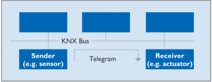
• Most of the data transmitted are not payloads (e.g. light on/light off signals), but ad-dress information (i.e. where have the data come from? Where are they going to?) Another important feature of the KNX bus system is its de-centralised structure: there is no need for a central control unit, because the “intelligence” of the system is spread across all of its devices. Centralised units are possible, however, for realising very specialised applications. Every device has its own microprocessor. A ma-jor advantage of KNX’s decen-tralised structure is that, if one device fails, the others contin-ue to function. Only those ap-plications dependent on the failed device will be interrupt-ed. Generally in a KNX sys-tem, devices fall into three cat-egories: system devices (pow-er supply, programming int(pow-er- inter-face, etc.), sensors, and actua-tors. Sensors are devices that detect events in the building (e.g. someone pressing a but-ton, someone moving, a tem-perature falling above or be-low a set value, etc.), convert these into telegrams (data packets), and send them along the bus network. Devices that receive telegrams and convert the commands embedded in them into actions are known as actuators. Sensors issue commands, while actuators receive them (Fig. 4).
How big can a KNX system be?
Thanks to their decentralised structure, KNX bus systems can be modified and added to exactly as required. The smallest possible KNX appli-cation is a system linking two bus devices: a sensor and an actuator. This basic system can later be upgraded with as many devices as necessary to perform the desired control tasks. Theoretically a KNX system can consist of more than 50,000 devices. When extending a KNX system it is necessary to adhere to a spe-cific topology.
What communication media are available? Various communication me-dia (and hence transmission methods) can be used for the exchange of data between devices in a KNX system: • KNX Twisted Pair (KNX TP)
– communication via a twist-ed pair data cable (bus cable) • KNX Powerline (KNX PL) – uses the existing 230 V mains network
• KNX Radio Frequency (KNX RF) – communication via radio signal
• KNX IP – communication via Ethernet
• In situations where the cus-tomer wants a large num-ber of different functions, a bus system will be easier and cheaper to install than an equivalent conventional installation
• In situations where the cus-tomer wants a large number of different functions, a bus system will also be less com-plex than a traditional instal-lation
• Continuous energy savings and hence lower operating costs
• Greater comfort and con-venience
• Easier to operate for older people/conducive to senior-friendly living
• Flexible, future-proof instal-lations
• Safety/security (presence simulation, alarms in case of break-in attempts, freezer door alarms, panic buttons with telephone link, etc.) Electrical installations are changing. Customers need to be shown the benefits of a fu-ture-proof KNX installation, in order to make an informed de-cision about whether the ini-tial higher investment is justi-fied by the long-term reduc-tion in operating costs. Already, new commercial and institutional buildings, in oth-er words schools, events ven-ues, offices, hotels, doctors’ surgeries, law firms and pro-duction sites, are generally equipped with KNX bus in-stallations. In these buildings bus technology often costs less than a conventional elec-trical installation even in the wiring stage. The benefits of bus technology are undenia-ble (Fig. 3).
Figure 4. Sensor/actuator principle Telegram KNX Bus Sender
KNX communication media
Bus systems need to be very convenient to install, add to, and in general to work with. The wide selection of KNX communication media available means that what-ever the requirements, KNX can meet them – for exam-ple when retrofitting bus de-vices in even the most laby-rinthine of buildings.
KNX Twisted Pair (TP) A two-core twisted pair data cable (bus cable) is the most common communication me-dium for KNX installations. Here all devices are connect-ed with one another via the bus cable. Twisted pair cables are cost-effective to buy and easy to install.
Power supply
In KNX TP the bus cable sup-plies all bus devices with both data and power. The rated voltage of the bus system is 24 V, while the voltage pro-vided by the power supplies is 30 V. The bus devices work without error at voltages be-tween 21 V and 30 V, so a tol-erance range of 9 V is availa-ble to compensate for voltage drops in the cable, and contact resistance. In the devices, the DC supply voltage is first of all separated from the data-carrying AC voltage. The DC supply voltage is created by a capacitor, while a transform-er decouples the data-carry-ing AC voltage. In transmit-ting devices, the transformer also serves to superimpose the outgoing data onto the bus voltage.
Data rate and signal shape
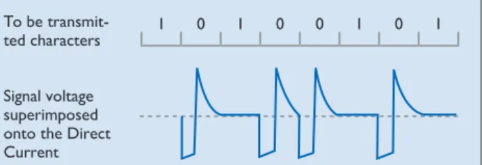
The data transfer rate is 9,600 bit/s, and the data trav-el serially, one byte at a time, via asynchronous data transfer. When a logical zero is trans-mitted, the voltage drops brief-ly and then, after no more than 104 µs, increases again to even
out at the original voltage. This is due to the inductor effect of the choke. The transmission of logical ones corresponds to the idle state of the bus
(Fig. 5). An important feature of communication via KNX TP is that the signals are cou-pled symmetrically onto the bus, i.e. the data cable has no fixed reference point against earth. This kind of communi-cation is known as symmetri-cal, non-earthed transmission. The receiver does not regis-ter the voltage to earth in an individual data cable (like e.g. in the USB port), but instead evaluates changes in the volt-age difference between the two data cables (Fig. 6). This
means that, without any signif-icant additional hardware, sta-bility against coupled interfer-ence signals increases signifi-cantly, because e.g. the inter-ference signals on both cores counterbalance each other (differential). The transmitter creates the AC voltage corre-sponding to the logical zero by only sending a half-wave, which it does by lowering the voltage on the pair of cores in the data cable by around 5 V. After ap-proximately half a bit period, the sender cancels this volt-age drop again. The rest of the system – the bus cable, trans-formers and charging capaci-tors of all bus devices, and – very importantly – the choke
of the power supply, then gen-erates a positive compensat-ing pulse (resonator).
Telegram structure
Information is exchanged be-tween bus devices in the form of so-called telegrams. A tel-egram consists of a sequence of characters, with each char-acter consisting of eight zeros and ones, in other words eight bits, or one byte. Often sev-eral characters are combined with one another to form a field. KNX TP telegrams have four fields (Fig. 7):
• The control field defines the priority of the telegram and whether or not transmission of the telegram was repeat-ed (if the receiver did not re-spond)
• The address field specifies the Individual Address of the sender and the destina-tion address (Individual Ad-dress or Group AdAd-dress) of the receiver
• The data field, which can be up to 16 bytes long, contains the telegram’s payload • The checksum field is used
for parity checks
Bus access method
Access to the KNX bus, like several other bus systems, is random and event-driven. A telegram can only be trans-mitted if no other telegram is being transmitted at the same time. To prevent col-lisions during transmission, the priorities of the various sending devices are regulat-ed by the CSMA/CA (Car-rier Sense Multiple Access/ Collision Avoidance) method (Fig. 9).
Each transmitting device lis-tens in to every bit of data transfer along the bus. If two devices are sending a telegram at the same time, then inevi-tably (and no later than at the moment of transmission of the sender address in the address Signal voltage
superimposed onto the Direct Current To be
transmit-ted characters 1 0 1 0 0 1 0 1
Figure 5. Signal shape in KNX TP
Control field
KNX TP Telegram Address
field Datenfeld Checksum field 1 Byte 5 Byte 1 to 16 Bytes 1 Byte
Data field
Figure 7. Telegram structure in KNX TP Figure 6. Symmetrical data transfer
Signal Interference radiation DVC DVC DVC = Device + – + –
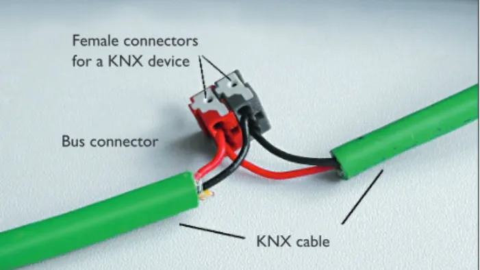
Figure 8. Bus terminal with incoming and outgoing bus cable KNX cable Bus connector
Female connectors for a KNX device field), one sender will transmit
a 0 while the other wants to transmit a 1. The device send-ing the 1 “hears” that a 0 is be-ing transmitted along the bus, and detects the collision. It is obliged to abort its own data transmission and give priori-ty to the other transmission. After the transmission tak-ing priority is complete, the aborted data transmission re-commences. A telegram’s lev-el of priority can be defined in its control field; this enables the designer of the system to specify which telegrams have “right-of-way” in case of col-lision. If two telegrams have the same level of priority, which telegram is allowed to be sent first is determined by its physical address (0 has pri-ority over 1).
Connection of bus devices
Bus devices are connected to the data cable via components known as bus terminals – plug-in termplug-inals able to accom-modate up to four KNX ca-bles. The bus terminals make it possible to disconnect devic-es from the bus without inter-rupting the bus line. This rep-resents a key benefit of the KNX bus system: removing a single bus device from the system does not stop the oth-er devices from communicat-ing with one another (Fig. 8). KNX Powerline (PL) Using the existing electrici-ty cables in a building as the KNX communication medium is a cost-effective way of ret-rofitting a building with KNX. In KNX Powerline (KNX PL) there is no need to lay a dedi-cated bus cable: the electricity cables already installed (one of the three phases + the neutral wire) themselves become the communication medium. The data signals are superimposed onto the mains voltage.
Power supply
No additional power supplies are needed for KNX PL; the power required by the bus de-vices comes from the 230 V mains electricity grid. Phase
Telegram visible on the bus = Telegram 2 Telegram 1 1 0 1 1 0 1 0 1 Telegram 2 1 0 1 0 0 1 0 1 Abortion of transmission of telegram 1 Collision
Figure 9. Collision avoidance in KNX TP couplers are used to ensure
that data communication can take place via all three phases, while band-stop filters prevent the propagation of data signals through the building connec-tion towards the mains grid. Alternatively, instead of phase couplers, system couplers can be used.
Data rate and signal shape
In KNX PL the data transfer rate is 1,200 bit/s. Logical ze-ros and ones are transmitted via spread frequency shift key-ing (S-FSK). A signal of frequen-cy 105.6 kHz sent by a trans-mitter corresponds to a logi-cal zero, while a logilogi-cal one is represented by a frequency of 115.2 kHz (Fig. 10). The signals are superimposed onto the mains voltage. Thanks to com-parative techniques and an in-telligent corrective procedure, signals received can be evaluat-ed even when interference is present. The centre frequen-cy of the two wave motions is 110 kHz, which is why the KNX PL system is also known as PL110. The transmission power of the superimposed signals is often equal to the level of noise on today’s high-ly noise-polluted mains net-works. As a result they can only be evaluated using spe-cial digital signal processing methods, in which the trans-mission power and receptive sensitivity of the bus devices are constantly adapted to the network conditions.
Telegram structure
KNX PL telegrams are essen-tially extended KNX TP tele-grams. KNX PL telegrams have four fields (Fig. 11):
• The training field synchro-nises and sets the levels of senders and receivers • The preamble fields indicate
the start of transmission, con-trol access to the bus, and are needed to prevent telegrams from colliding
• The third field contains the KNX TP telegram
• The system ID field contains an ID for keeping the signals of different KNX PL systems
separate, so that only devic-es using the same system ID can communicate with one another.
Bus access method
Like KNX TP, KNX PL re-quires the use of a bus access method to prevent collisions between telegrams. This can
only be done by delaying the sending of telegrams by bus de-vices. The default state of all bus devices is receive mode; only if certain conditions are met are they able to switch to sending mode. If a device de-tects the bit string of a pre-amble, this indicates to it that the bus is occupied by anoth-Signal voltage
superimposed onto the mains To be
transmit-ted characters 1 0 0 1
Figure 10. Signal shape in KNX PL
Training Sequence
KNX PL Telegram 2 Preamble
fields System ID
4 Bit 2 Byte 9 to 23 Byte 1 Byte Complete
KNX TP Frame
er device. A differentiation is made between the two states Bus occupied and Bus blocked. If a device receives a Bus occu-pied signal, the transmission of its telegram is postponed until a later point in time, chosen at random from one of seven possible options. This hugely reduces the likelihood of col-lisions occurring.
Connection of bus devices
In KNX PL, bus devices are connected directly to the 230 V mains network. KNX Radio Frequency (RF) Radio is always an appropriate KNX communication medium in those situations where it is not possible to lay new cables in the building (e.g. for sensors in inaccessible areas). KNX RF is also particularly suitable for extending existing KNX TP installations. Theoretically KNX RF could allow all tech-nology in a building to be con-trolled wirelessly, but this will remain the exception rather than the rule.
Power supply
To enable RF sensors to be positioned where they do not have access to mains power, they are generally fitted with batteries. This is only possible if these devices do not need to be in a permanent ready-to-receive state. To help here, a unidirectional device model has been defined in KNX that only sends telegrams when needed, and does not contain a receiver. Actuators, on the other hand, need to be able to receive at all times, so need to be bidirectional. RF actua-tors therefore generally take their power from the 230 V mains. In KNX all receivers must also be able to transmit. The unique capabilities of KNX shine through when consider-ing the performance of the sys-tem as a whole.
Data rate and signal shape
Radio technology works by modulating a carrier wave with the information that needs to be sent. This can be
done by modulating either its amplitude (amplitude modu-lation), frequency (frequen-cy modulation), phase (phase modulation), or a combina-tion thereof. The modulated signal is sent to the receivers which then demodulate it, i.e. recover the information from it. KNX RF uses frequency modulation (Fig. 12). The log-ical states zero and one are produced by slightly modify-ing the frequency of the car-rier wave, also known as the centre frequency.
Choosing the correct centre frequency is an important fac-tor in determining the trans-mission performance. There are two upwards-compatible versions of KNX RF – KNX RF Ready and KNX RF Multi. In KNX Ready the centre fre-quency is 868.3 MHz, and only one communication chan-nel is available. However, ra-dio communication in which only one channel is available is vulnerable to interference from non-KNX radio systems in the same or adjacent band that use different methods for accessing the communication medium.
KNX RF Multi overcomes this interference by enabling de-vices to switch from an occu-pied channel (e.g. F1, which is identical to the channel used by KNX RF Ready) to a dif-ferent radio channel, i.e. ideal-ly two other fast channels (F2 and F3), or two slow channels
(S1 and S2). The fast chan-nels are intended for appli-cations operated by humans, e.g. lights, blinds, etc., while the slow channels are for de-vices that do not need to be permanently in receive mode, e.g. HVAC control systems. Fast channels have a data rate of 16.384 kbps, slow channels only half of that.
While the data transfer rate (duty cycle) in F1 and F2 can only be 1 % or 0.1 % at a max-imum of 25 mW, for chan-nels F3 and S1 it can be in-creased to 100 % at a maxi-mum of 5 mW (but between 5 and 25 mW again only 1 %). The data transfer rate in chan-nel S2 is limited to 10 % at a maximum of 25 mW.
Although devices are always capable of sending telegrams, they are switched to sleep mode to reduce their con-sumption by up to 80 % for fast channels and as much as 99 % for slow channels, wak-ing up only periodically in or-der to receive telegrams. To ensure compatibility be-tween single and multi-chan-nel devices, a compatibili-ty scheme has been devel-oped, whereby newly-devel-oped single-channel devices now need to use longer pre-ambles. It must be possible for multi-channel devices to be downgraded to single-chan-nel devices.
KNX RF Multi also makes it possible to check that a tele-gram has been received cor-rectly: fast, direct acknowl-edgement of receipt (Fast
IACK) can be obtained from up to 64 individual receivers. If no Fast IACK is received, transmission of telegrams is automatically repeated. In larger installations, retrans-mitters can be used to for-ward telegrams to distant in-stallation locations. Media cou-plers can be used for coupling KNX RF systems with KNX TP systems.
Telegram structure
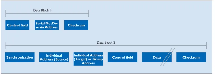
Like with all KNX communi-cation media, in KNX RF the useful data are sent via multi-cast telegrams. This means that one telegram can be received by several bus devices simulta-neously and so e.g. switch on several lights at once. KNX RF telegrams are made up of several data blocks separat-ed by checksum (CRC) fields
(Fig. 13). The data blocks con-tain the actual payload as well as bus-specific information for addressing purposes. The first data block consists of three fields (Fig. 14): the first – the control field – contains infor-mation about the length of the telegram, the transmis-sion quality (reception per-formance), the battery sta-tus of battery-operated KNX RF devices , and whether the device is unidirectional, while the second field contains ei-ther the KNX serial number or the domain address. The serial number is assigned by the manufacturer and cannot be changed.
In commissioning in E- Mode, the serial number is evaluat-ed in the receiver together with the source address of the sender.
In KNX RF S-Mode devices, the domain address is assigned in ETS (version 5 or higher), and serves to keep neighbour-ing RF systems separate from one another.
The third field, the checksum field, allows the receiver to determine whether or not a telegram has been sent with-out error. In addition to fur-ther control fields and check-sum bytes, the second data Figure 12. Frequency modulation and signal in KNX RF
Information signal (Baseband signal) Carrier Frequency shift keying 1 0 1 1 0 mF mT an t t 0 T 2T 5T
block consists of fields con-taining the individual source address (physical address), the destination address, and the payload. The payload is the actual information that is to be sent. Depending on the length of the payload, a KNX telegram can also contain fur-ther data blocks.
Bus access method
Unidirectional devices only send telegrams when nec-essary. Because of the very small duty cycle (= the pulse duration as a percentage of the complete period) of 1 %, it is virtually impossible for telegrams to collide, even in KNX RF Ready. Bidirectional devices check before sending a telegram whether the radio channel is free. If the channel is occupied, the device waits un-til it is free again before send-ing the telegram. As already mentioned, in KNX RF Mul-ti the sender can request ac-knowledgement of receipt of the telegram.
Connection of bus devices
KNX RF components can be flush-mounted, surface-mounted, or built-in. Flush-mounted devices are mainly inserts onto which operating buttons are mounted to en-able lights to be switched on and off or dimmed, or drive mechanisms for blinds to be operated. The radio com-munication components can be integrated either in the push-on interface or in the device insert. Various sen-sors, actuators and combina-tion units are available as sur-face-mounted/built-in devices suitable for mounting, gluing or integrating in any desired location and on any surface. KNX IP
Ethernet is an open (manufac-turer-independent), high-per-formance, local and wide area network compliant with the international standard IEEE 802.3 (Ethernet). Ethernet is used for local networks, par-ticularly in conjunction with
the internet. Throughout the world there are a wide varie-ty of different network struc-tures. The Ethernet stand-ard defines the physical ar-eas (network engineers call them layers) – i.e. for exam-ple the following:
• What form the signals take in the cable
• What cables are used • Cable pin configurations • How the various devices can
access a common system • How the characters being
sent are represented • What data backup methods
are used
For sending data between two devices, these definitions are generally not sufficient, how-ever. Numerous other de-tails concerning the protocols used also need to be defined; this is particularly important in large networks (internet). Protocols are needed in order for computers to communi-cate with one another in the network. TCP/IP – a group of protocols or rules (protocol
KNX RF Telegram
Synchro-nisation Data Block 1 Checksum Data Block 2 Checksum Data Block ... Checksum Synchro- nisation
10 Byte 2 Byte 16 Byte 2 Byte 2 Byte
Data Block 1
Control field Serial No./Do-main Address Checksum
Data Block 2
Synchronization Address (Source)Individual Individual Address (Target) or Group Address
Control field Data Checksum
Figure 13. Telegram structure in KNX RF
Figure 14. Data blocks in a KNX RF telegram
family) introduced in 1984 – is currently very widely used. Although usually discussed in the form “TCP/IP”, TCP (Transmission Control Proto-col) and IP (Internet ProtoProto-col) are in fact two distinct proto-cols. Strictly speaking, the in-ternet protocol suite TCP/IP also includes a third, equal-ly important protocol: UDP (User Datagram Protocol). The base protocol, IP, serves to ensure that the data pack-ets are sent from one device to another, and that in doing so they follow the optimal routes. This is made possible by so-called IP addresses. The TCP protocol is based on the IP protocol, and is used for a large number of common network applications, e.g. e-mail and surfing the internet. The TCP protocol establishes a permanent, error-checked connection and ensures that all data packets are sent in the correct order and suc-cessfully reconstructed by the receiver
(connection-orient-ed protocol). The UDP pro-tocol is used for applications (e.g. audio and video stream-ing) in which it is acceptable for data packets to occasion-ally go missing. The connec-tion is not error-checked, and the delivery of data packets is uncontrolled (connectionless protocol). UDP is considera-bly leaner and faster than TCP. In applications like the trans-mission of speech and video, it would also be counter-pro-ductive to resend – e.g. a sec-ond later – a packet that has gone missing. The UDP pro-tocol is often used in building automation. Linking KNX to the Ethernet has the follow-ing advantages:
• The existing network infra-structure in the building can be used for the KNX main and backbone lines (higher speed, more cost effective, and more convenient) • Buildings can be monitored
and controlled via Ethernet from anywhere in the world • Several individual sites can be observed and maintained from a central location over the internet
• KNX customer installations can be analysed and pro-grammed remotely over the internet by the designer of the KNX system
Protocol
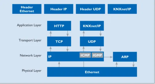
The KNX system uses two Ethernet communication methods – tunneling and routing – both of which use the UDP protocol. Tunneling is used to access the bus from a local network or the inter-net for purposes of e.g. pro-gramming the KNX installa-tion, while routing is used for exchanging telegrams over an Ethernet network, e.g. to cou-ple two KNX TP systems via Ethernet. The KNX protocols for these two communication methods are called KNXnet/ IP routing and KNXnet/IP tunneling. IP communication in KNX can be explained us-ing the OSI reference model
(Fig. 15). Communication takes place via the application layer (which generates the KNXnet/
IP telegram), the transport lay-er (UDP), the network laylay-er (IP), and Ethernet – the phys-ical layer. Like with the TP protocol, additional informa-tion for the respective layer (the header) is always added to the KNXnet/IP information.
Telegram structure
The KNXnet/IP telegram con-tains some further information in addition to that in the KNX TP telegram (Fig. 16): • Header Length
The header length is always the same. This information is still sent, however, be-cause the header length may change in a later version of the protocol. The purpose of the header is to identify the start of the telegram. • Protocol Version
This indicates what version of the KNXnet/IP protocol applies.
• KNXnet/IP Service Type Iden-tifier
The KNXnet/IP Service Type Identifier indicates the action that is to be carried out. • Total Length
This field indicates the total length of the KNXnet/IP tel-egram.
• KNXnet/IP-Body
This field contains the pay-load.
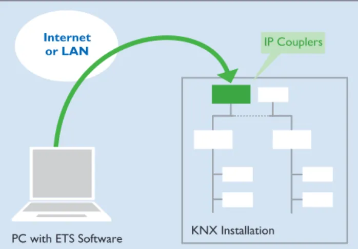
KNXnet/IP tunneling
Tunneling is needed where ETS is to be used to send KNX telegrams in a connection-oriented manner within an IP framework (Fig. 17). In princi-ple this is always the case if a physical address is to be used as the destination address (e.g. when programming the phys-ical address/downloading the application software for KNX devices). In tunneling, commu-nication always takes place via the IP address of the KNXnet/ IP device that is being used for tunneling.
KNXnet/IP routing
Routing is needed for the si-multaneous, connectionless transmission of KNX tel-egrams to several partici-pants via a KNXnet/IP rout-er (Fig. 18). This is equivalent to group communication in e.g. KNX TP. Routing is used for e.g. coupling TP cables. A KNXnet/IP router serving as a line coupler for a KNX TP cable will only send a tele-gram to the IP side if the cor-responding group address ap-pears in the filter table of the KNXnet/IP router. All other KNXnet/IP routers serving as line couplers for other KNX TP lines will only transmit the telegram from the IP side to their KNX TP line provided that the relevant group ad-dress appears in the filter ta-bles of the KNXnet/IP routers. Application Layer
Header
Ethernet Header IP Header UDP KNXnet/IP
Transport Layer Network Layer Physical Layer HTTP TCP IP KNXnet/IP UDP Ethernet ARP ICMP IGMP
Figure 15. KNXnet/IP in the OSI reference model
KNXnet/IP
Header
Length ProtocolVersion Service type Identifier Total Length KNXnet/IP-Body
KNX IP and KNX TP compared
As communication via IP and Ethernet grows in significance, it is reasonable to ask wheth-er the popularity of Ethwheth-ernet will eclipse that of the cur-rent most popular, established KNX medium, TP. The answer is no. The main reasons for this are, firstly, the substan-tial cabling costs involved – because each terminal would need its own network cable. Secondly, networking KNX DIN rail modules in a switch cabinet via Ethernet would be too time-consuming, because of the very large number of network switches needed. Their high energy consump-tion furthermore means that they are not energy-efficient. IP does not pose a problem, however, if – by virtue of its function – a device has a net-work connection anyway (e.g. a KNX display). Thus, through the integration of KNX sys-tem software, any device with a network connection can be turned into a KNX device without any additional hard-ware costs. So while the hier-archical topologies will clearly continue to prevail, Ethernet will become increasingly estab-lished as a high-performance backbone and a means of con-necting complex (KNX IP) de-vices. The benefits of KNX TP,
KNX Installation PC with ETS Software
Internet
or LAN IP Couplers
Figure 17. Example of KNXnet/IP tunneling: programming of bus devices via Ethernet
KNX Installation KNX Installation IP Couplers Internet
or LAN
Figure 18. Example of KNXnet/IP routing: accessing several KNX installations at once via Ethernet
KNX PL and KNX RF can be clearly seen in their suitabili-ty for linking together separate sensors and actuators. KNX is the only bus system to offer such a wide variety of com-munication media.
Data transfer rates compared
Despite its various different communication media availa-ble, KNX constitutes a single bus system. KNX systems can be designed and commissioned with just one piece of software (ETS). KNX bus devices differ only in the type of connection they use; this does not affect the way the devices commu-nicate with each other (the same Group Addresses apply throughout the system, com-ponents from different manu-facturers are mutually compat-ible, etc.). The various media do differ considerably in their data transfer rates, however. In normal data traffic, KNX TP needs around 20 ms to send a telegram. Only during the pro-gramming of devices does this increase – to 40 ms. A KNX TP bus can send a maximum of 50 telegrams per second. KNX PL, in contrast, offers a data rate of six telegrams per second, due to the low-er baud rate, longlow-er telegram structure, and different access method of this medium.
KNX topology
KNX systems can be addedto as desired, and can consist of several KNX subsystems based on different commu-nication media (TP, PL, RF, IP). To ensure problem-free transmission of telegrams between individual bus de-vices, KNX systems must ad-here to a specific topology.
KNX TP
Topology
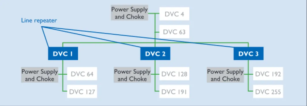
The basic unit of a KNX TP installation is a line (Fig. 19). A line includes a KNX power supply (including choke), and usually no more than 64 other bus devices. The power supply and twisted pair line (bus cable) perform two functions: they supply the bus devices with the power they need, and per-mit the exchange of informa-tion – i.e. the sending of tele-grams – between those devic-es. The bus cable can be laid as desired, and branches can be added at any point. The re-sulting topology is a free tree structure, which allows a great deal of flexibility in terms of layout. Line Repeaters can be used to extend a line if more than 64 devices are needed. Sections added in this way are known as line segments. A line segment consists of a line re-peater, a power supply (includ-ing choke), and no more than 64 further bus devices (line re-peaters count as bus devices in the line). No more than three repeaters can be operated in parallel in a line, meaning the maximum number of bus de-vices is 255 (Fig. 20).
Another way of expanding the installation is to create new lines using Line Couplers. Be-cause, in practice, line repeat-ers and Line Couplrepeat-ers (or Area Couplers) are often the same hardware, lines are not nor-mally extended to their maxi-mum size using line repeaters; new lines are generally
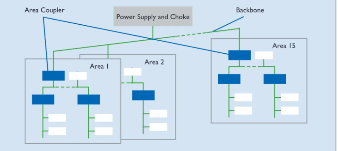
creat-ed instead. On the one hand this makes the system more manageable, and on the oth-er hand it reduces the num-ber of telegrams travelling along each line (by taking ad-vantage of the filter function of the line couplers). A Line Coupler will not send a tele-gram to a line for which it is not destined. Up to 15 lines can be operated via Line Cou-plers on a line – the main line – to form an area (Fig. 21). The main line can likewise accom-modate up to 64 devices. Line Repeaters cannot be used on the main line. Line Couplers in the main line count as bus devices. Each line needs its own power supply (including choke). Up to 15 areas can be added to an area line via Area Couplers, to form a complete system (Fig. 22). Just like the main line, the area line can ac-commodate up to 64 bus de-vices (not including Line
Re-peaters). Line Couplers on the area line count as bus de-vices. In practice, area cou-pling is typically performed using Line Couplers parame-terised as area couplers. The area line is also called the back-bone, so it also needs its own power supply.
The separation of the system into lines and areas has the following substantial benefits: 1. More reliable operation
thanks to galvanic separa-tion – lines and areas all have their own power
sup-plies. The system as a whole continues to work even if in-dividual power supplies fail. 2. Local data traffic on a line
or area does not affect the data rate in other lines and areas.
3. The topology is logical and manageable for commis-sioning purposes.
Cable lengths
For signal formation reasons, and due to the maximum per-missible propagation delay, distances in line segments are Figure 19. KNX TP line
DVC 1 DVC 3
DVC 2
DVC 5
DVC 64 Power Supply and Choke
DVC 4
Figure 20. Maximum length of a line in KNX TP
Line repeater DVC 4 DVC 63 DVC 2 DVC 128 DVC 191 DVC 3 DVC 192 DVC 255 DVC 1 DVC 64 DVC 127 Power Supply and Choke Power Supply
and Choke Power Supply and Choke Power Supply and Choke
Line Coupler Power Supply and Choke DVC 1 DVC 49
DVC 0 DVC 0 DVC 0 DVC 1 DVC 63 DVC 1 DVC 63 DVC 1 DVC 63 Power Supply
and Choke Power Supply and Choke Power Supply and Choke
Line 1 Line 15
Line 0
limited as follows:
• Distance from power sup-ply to device: max. 350 m • Distance between any two
devices in a line: max. 700 m • Length of a line segment:
max. 1,000 m
• Distance between two pow-er supplies (including choke) in a line: as per manufactur-ers’ specifications.
Individual Addresses
Every device in a KNX sys-tem is assigned a unique, un-ambiguous number – its Indi-vidual Address. This consists of three numbers separated by dots. The numbers depend on the position of the bus device in the topology:
• The first number denotes the number of the area • The second number denotes
the number of the line • The third number is a
se-quential number indicating the device’s position in the line.
Physical addresses are need-ed in order to identify devic-es clearly, and also to program them. A special point to note is that, when attributing phys-ical addresses, area/line cou-plers must always be given the number 0 as their sequential number.
Examples:
Physical address 1.1.0: line coupler coupling the first line with the main line in the first area.
Physical address 2.3.20: bus device 20 in the third line of the second area.
KNX PL
Topology
The topology in KNX PL is similar to that of KNX TP, and is made up of lines and areas. The basic unit of an installa-tion is a line containing a max-imum of 255 devices. An area is created by coupling 15 KNX PL lines using KNX TP; in PL the maximum number of are-as is eight, however. Instead of line couplers, in KNX PL sys-tem couplers are used. The individual KNX PL lines need to be separated from one an-other using band-stop filters.
System couplers, like all oth-er couploth-ers, have filtoth-er func-tions, which make it possible to reduce the number of tel-egrams in the various subsys-tems. Because the number of telegrams in a KNX PL instal-lation is considerably smaller than in KNX TP, using KNX PL can be a necessary meas-ure for preventing congestion in the bus system.
Individual Addresses
System couplers (like Area and Line Couplers) are assigned the sequential number 0. All other PL devices are as-signed a Individual Address corresponding to their posi-tion in the topology.
Examples:
Individual Address 1.5.0: sys-tem coupler coupling the fifth PL line with the TP main line in the first area.
Individual Address 2.3.20: PL bus device with sequential number 20 in the third line of the second area.
KNX RF
Topology
The devices in a KNX RF in-stallation do not need to be arranged hierarchically, and can be installed virtually an-ywhere. Provided that they are within range of one an-other, any sensor can commu-nicate with any actuator. It is not possible to limit the range of RF radio signals geograph-ically, i.e. KNX RF telegrams can be received by devices in other, nearby KNX RF
instal-Area 2
Area 15 Power Supply and Choke
Area 1
Area Coupler Backbone
Figure 22. Up to 15 areas can be coupled via area couplers in KNX TP. lations. It therefore needs to be ensured that neighbouring installations cannot interfere with one another. Telegrams sent by KNX radio transmit-ters always include the serial number/domain address of the device as a unique identifier. Only those receivers paired with the transmitter are able to process telegrams sent by it. A KNX system can be purely a radio network, or can bine radio with another com-munication medium (e.g. KNX TP). Media Couplers are used for coupling purposes.
Individual Addresses
Media couplers are assigned physical addresses corre-sponding to their position in the system topology.
Physical address 2.3.20: media coupler with sequential num-ber 20 in the third line of the second area.
KNX IP
Topology
KNX IP can be used in place of main and area lines. This requires the use of KNXnet/ IP routers. On the “top” of
KNXnet/IP routers is an Eth-ernet port and a KNX TP connection. The routers for-ward KNX telegrams to other KNXnet/IP routers using the routing method. The availa-bility of Ethernet as a further communication medium in-creases yet further the flexi-bility of KNX system topolo-gies. KNXnet/IP routers can be used both as Line Cou-plers (Fig. 23) and Area Cou-plers (Fig. 24). Like all cou-plers, KNXnet/IP routers are also able to filter telegrams. KNXnet/IP routers also make it possible to program devices in different lines. Some manu-facturers of KNXnet/IP rout-ers additionally support the fil-tering of telegrams with Indi-vidual Addresses, to prevent programming across different lines or areas if desired. During operation, KNXnet/IP routers communicate with one anoth-er and with the othanoth-er KNX devices in the system via Eth-ernet, using routing as a com-munication method.
Most KNXnet/IP routers also support tunneling, i.e. they can also be used as an IP pro-gramming interface for ETS.
Ethernet
KNXnet/IP Router
Twisted Pair Lines
KNXnet/IP routers can addi-tionally be used to connect en-tire separate systems with one another via Ethernet (Fig. 25). This can be useful if e.g. two buildings are each equipped with a KNX twisted pair sys-tem, and these two installa-tions need to be combined into a single system. If there is already an Ethernet connec-tion between the two buildings (which will often be the case in commercial and institution-al buildings), then there is no need to lay a new cable be-tween them. KNX IP can also be used to network KNX de-vices, e.g. KNX displays, with one another. Software is avail-able for communicating with KNX systems via KNXnet/IP.
Cable lengths
Ethernet installations are con-nected using network cables. Various types of network ca-ble are availaca-ble, each using a different method for shielding the cable cores. It is general-ly not permitted for these ca-bles to be longer than around 100 m. For longer installations, special network components are needed to join together individual network segments. In residential buildings cable length is not usually an issue. As already mentioned, in com-mercial and institutional build-ings the existing network infra-structure can be used. Figure 24. Coupling of KNX TP areas with KNXnet/IP routers
KNX TP Area n KNX TP Area 3 KNX TP Area 2 KNX TP Area 1 EthernetKNXnet/IP Router KNXnet/IP Router KNX Installation KNX Installation Internet or LAN
Figure 25. Coupling of two KNX systems at separate locations
KNXnet/IP Router
Individual Addresses
KNXnet/IP routers (routing) are given the sequential num-ber 0 (like area and line cou-plers). KNX IP interfaces (tun-neling) can be given any se-quential number.
Examples:
Individual Address 1.5.0: KNXnet/IP router acting as a line coupler, coupling the fifth line with the main line in the first area.
Individual Address 2.3.20: KNX IP programming inter-face with sequential number 20 in the third line of the sec-ond area.
Figure 26. Example of KNX topology incorporating all media (TP, PL, RF, IP)
Mixed topology
All of the topologies for the various communication me-dia (TP, PL, RF and IP) can be used in combination with one another if desired (Fig. 26).
1.1.64 1.15.64
2.1.0
2.1.63 2.1.128
Line Coupler Line Coupler
Line Coupler Line Repeater Main Line Main Line 2.0.1 2.0.63 TP Power Supply and Choke 1.0.1 1.0.62 Power Supply and Choke IP-Router IP-Router 1.15.0 1.1.0 1.1.1 Power Supply and Choke 1.15.1 Power Supply and Choke 2.1.1 Power Supply and Choke Media Coupler 2.0.0 1.0.0 Ethernet IP Backbone TP 2.15.0 System Coupler 2.15.1 2.15.255 2.1.65 Power Supply and Choke PL 2.1.64
Figure 27. Components of a bus device Bus cable PEI Bus Coupling Unit Bus Device
Figure 28. Components of a bus coupling unit Bus cable
PEI Transmission
module Controller
KNX devices
There are two kinds of de-vices in a KNX system: sys-tem devices and end devic-es. System devices can be e.g. power supplies, cou-plers or programming inter-faces, while end devices are e.g. sensors and actuators.Sensors, actuators and bus coupling units
Components of bus devices
All standard bus devices are made up of two parts – the bus coupling unit (BCU) and the application module (Fig. 27). If these two components are separable, they are connected via a standardised, 10 or 12-pin physical external interface (PEI). If a device was assembled in the factory – as is the case with built-in devices and most devices designed for DIN-rail mounting – it will not be pos-sible to access the PEI.
Components of bus coupling units
For bus coupling units that are permanently integrated into devices, manufacturers can use either a ready-made Bus Interface Module (BIM), or a KNX chipset. In those device types where the bus coupling unit is a separate device con-nected with the end device via the PEI, the bus coupling unit will be visible. A wide variety of different designs are avail-able (flush-mounted, DIN-rail mounted, and printed circuit boards for integration into cir-cuits), but all bus coupling units are essentially similar in struc-ture, consisting of two func-tional modules: the bus cou-pling unit controller, and the transmission module (Fig. 28). The transmission module de-termines the communication medium which the bus cou-pling unit will use. The most common bus coupling units are those with transmission
modules for KNX TP (Twist-ed Pair) and for KNX PL (Pow-erline). The functions of these two types of transmission module are as follows: • KNX TP: superimposing the
data signal onto the DC sup-ply voltage
• KNX PL: superimposing the data signal onto the 230 V mains power.
Both types of transmission module also contain a pow-er supply for the bus coupling unit controller, and generate reset and save pulses for the microcontroller. The bus cou-pling unit controller is essen-tially a microcontroller – a chip incorporating a microproces-sor and various memories and input and output peripherals. The microprocessor will be a standard e.g. NEC, ATMega or Texas Instruments controller
with the following memories: • RAM: the smallest memory. Variable parameters gener-ated during operation of the device are stored here. • EEPROM or flash memory:
the data (e.g. parameters, physical addresses and group addresses) input by the user in the application software are stored in this memory. The contents of this memory areis downloaded from the PC to individual devices, to be programmed, where the data is then stored. • ROM: the system software
for the bus coupling unit is stored in this memory, dur-ing production of the chip. There are already several different development lev-els and versions, known as masks. A mask consists of two bytes of data, the first
digit of which – y – indicates what medium is used (0 for TP, 1 for PL110, 2 for RF and 5 for KNXnet/IP). Not all profiles exist on all of these media.
• The last digit, x, identifies the profile version.
The following masks serve to notify ETS of what sys-tem profile is used: » y01xh: System 1 » y02xh: System 2 » y70xh: System 7 » y7Bxh: System B » y300h: LTE » 091xh: TP line/area cou-plers – repeaters » 190xh: TP-PL110 media couplers » 2010h: RF bidirectional Easy devices » 2110h: RF unidirectional Easy devices
For a long time, System 1 was the most common profile. However, Systems 2, 7 and B – a progression on System 1 – are now gradually replac-ing System 1. They offer more memory and so allow a larg-er numblarg-er of Group Objects and Group Addresses to be used. All functions required for e.g. alarm systems have additionally been revised (e.g. data access management via password protection). Ap-plication software developed for System 1 can be down-loaded to devices with a Sys-tem 2 mask. Many suppliers of KNX devices now no long-er offlong-er any System 1 devices. Advanced bus devices use Sys-tem 7 or B, which offers con-siderably more memory than even System 2. The 10 or 12-pin connection between the bus coupling unit and the bus end device can be used in very different ways depending on the requirements. Depending on the end device used, the data exchanged via the con-tacts can take the form of bi-nary signals, analogue signals, or a data stream via a serial interface. The way in which
the contacts is used is deter-mined on the basis of a resis-tor in the end device, which is measured by the bus cou-pling unit. Some end devices have their own “intelligence”, possibly even in the form of another microcontroller. In this case the function of the bus coupling unit is often sim-ply to manage the group ad-dresses and ensure protocol-compliant data traffic. In rare cases it does not even man-age the group addresses, act-ing – like the serial interface – merely as a gateway to the KNX bus.
System devices
KNX system devices are de-vices that perform primarily special functions, e.g.
• Facilitating adherence to the KNX topology
• Power supply • Programming
KNX TP power supplies
KNX power supplies supply KNX TP lines with the nec-essary bus voltage, and pro-vide the power needed for data transmission.
KNX TP USB interfaces
A KNX TP USB interface is needed in order to program the KNX system from a com-puter.
KNX TP line couplers/area couplers
These devices are used for the coupling of KNX TP lines and areas. They can also act as line repeaters.
KNX PL band-stop filters
KNX PL band-stop filters pre-vent powerline telegrams from leaving the intended propaga-tion range. They are single-phase devices so should be fitted to all phases. Here it is important to adhere to the maximum current capacity of 63 A per device.
KNX PL phase couplers
In a three-phase network it should be ensured that KNX PL signals reach all three phas-es. If the three phases are rout-ed in parallel in some sections, this will often take place auto-matically. If this is not the case, a phase coupler can help by providing capacitive coupling between the three phases of the 230 V network.
KNX PL system couplers
KNX PL system couplers can be used as repeaters for data signals in the 230 V network. They can also be used as line couplers for coupling sever-al KNX PL lines, or as media couplers for coupling KNX PL systems with KNX TP systems.
KNX RF Media Couplers
KNX RF media couplers are used to couple KNX RF stallations with KNX TP in-stallations.
KNXnet/IP routers
KNXnet/IP routers support the protocols KNX IP rout-ing and KNX IP tunnelrout-ing, and can be used for coupling lines and areas. KNXnet/IP rout-ers can also be used as a pro-gramming interface.
KNXnet/IP interfaces
KNXnet/IP interfaces are used for programming KNX sys-tems from the Ethernet side.
Table 1. What bus cable is used depends on the place of theinstallation. RECOMMENDED BUS LINES
Cables typically used in Germany Applicable constraints YCYM 2 x 2 x 0.8
Test voltage: 4kV (“KNX cable”)
Suitable for inside buildings
J-Y(St)Y 2 x 2 x 0.8 Test voltage: 2.5kV
Laid like YCYM, but note lower test voltage in proximity to 230 V mains
JH(St)H 2 x 2 x 0.8 Halogen-free cable, must ho-wever be installed at a distance from the existing 230 V instal-lation
A-2Y(L)2Y or A-2YF(L)2Y Used outdoors (linking separate buildings)
Figure 29. Minimum distances between bus cables and mains lines
KNX installation requirements
A KNX installation is a standard electrical instal-lation in the 230 V range, so all requirements appli-cable to standard installa-tions (VDE 0100, etc.) also apply to KNX. There are also some KNX-specific as-pects to consider.
KNX TP
No safety precautions are needed when installing/lay-ing bus lines, because the bus voltage meets the require-ments of safety extra-low volt-age (SELV) and can therefore be touched. Because the ab-sence of interference during the transmission of data be-tween the individual bus de-vices depends on what cable is used, the KNX standard includes precise stipulations about what bus cables are ac-ceptable. The cable must be a shielded twisted pair cable (Ta-ble 1), and the shielding on the cable must not be contacted or connected to earth on any side – it functions purely as a metal cage. In KNX TP, mains cables must not be used as bus lines because of the risk of confu-sion and their non-compliance with the applicable communi-cation requirements.
Second twisted pair
The most common bus ca-bles also include a second, free twisted pair. The follow-ing guidelines apply with re-gard to the use of this free pair: • Only extra-low voltages (SELV/PELV) are permitted • Max. 2.5 A continuous cur-rent, overload protection required
• Cannot be used as a circuit for public telecommunica-tions networks
• The second twisted pair is used to provide a separate power supply for particular-ly power-intensive KNX de-vices
Laying the cables
There are special issues to bear in mind wherever bus cables could come into contact with mains cables, e.g.
• In switch cabinets and dis-tribution boards
• In branch boxes
Between the bus voltage and the 230 V network, double in-sulation capable of withstand-ing a test voltage of 4 kV is generally required. Minimum spacings apply, depending on the installation system used
(Fig. 29). If switch cabinets are used in which the mains sec-tion is fully separated from the installation bus (i.e. there must be no 230 V actuators present), then no special re-quirements apply. The shield of bus cables must continue right up to the terminals, and the use of shield bonding bars is not permissible. Mains and bus cables should be routed and/or affixed in such a way that they do not touch. Spe-cial requirements apply for junction boxes only if both the bus cable and the 230 V ca-ble are stripped. For branch-ing, either separate boxes or a compartmentalised box with two separate chambers should be used. Special requirements apply for “combinations”, i.e. where a bus component and a mains component are housed under the same cover, e.g. a flush-mounted actuator with a socket outlet controlled via the bus. When the common cover is removed, the mains side must remain covered, as is the case in socket outlets protected against direct con-tact. Bus cables should ideally be laid together with the mains and hence in the standard in-stallation zones (for Germany see DIN 18015-3). There are several different methods for routing bus cables in individual rooms: they can be arranged in a star topology around a cen-tral distribution board, or a
ring topology passing through all of the rooms, or a combina-tion of the two. An important aspect to consider before un-dertaking a KNX installation is the extent to which a conven-tional installation and a KNX installation should, or indeed can, be combined, e.g. how appropriate it is to use KNX binary inputs in conjunction with conventional push but-tons rather than KNX push-button sensors. This is particu-larly important if the customer has not yet fully decided on a KNX system, but would like to
keep open the option of add-ing KNX components at a lat-er stage. Thlat-ere are essential-ly two ways to proceed here: • Lay a bus cable now but add
KNX components later • Use a star topology for the
conventional installation (e.g. wire each push button individually up to the distri-bution board), to allow the system to be retrofitted with KNXcentrally in the distri-bution board.
It is therefore important to leave enough space in the dis-tribution board.
230 V e.g. NYM
YCYM or J-Y(St) Y (2,5 kV) Insulated single core 230 V adjacent to the sheath of the bus cable
Insulated single core of the bus adjacent to the sheathed mains cable
230 V e.g. NYM
YCYM or J-Y(St) Y (2,5 kV) Exposure of two single cores
YCYM or J-Y(St) Y (2,5 kV) 230 V e.g. NYM KNX TP KNX TP KNX TP * * * > = 4 mm clearance space or additional insulation
KNX PL
Because KNX Powerline sends data along the exist-ing mains network, no spe-cial KNX installation require-ments apply here. Devices for limiting the transmission range (band-stop filters) and coupling the phases (phase coupling) are however need-ed. Circuit breakers or resid-ual-current devices with rat-ed currents of <10 A are not permissible in the signal cir-cuit of a Powerline system; fuses must be used instead. Nor can shielded cables with an earthed shield or cables with core cross sections of more than 25 mm² be used for data transmission. All KNX PL devices have a connection for one phase and the neutral line. In actuators the connec-tions for the load voltage and the signal cable are separate, so in installations with a very large amount of interference, it can make sense to separate the load and signal circuits. KNX RF
When planning KNX RF instal-lations, the potential effects of building structures and oth-er physical factors should be borne in mind. Under favour-able conditions, the transmis-sion range of a battery-pow-ered device is approximate-ly 100 m.
KNX IP
Network cables for KNX IP are subject to the same re-quirements as cables in IT networks.
The ETS software
A single manufacturer-inde-pendent Engineering Tool Software is used to plan, de-sign and commission KNX installations with KNX-cer-tified products: ETS®.
Sys-tem integrators can use this tool for connecting products from different manufactur-ers and from different ap-plication domains to form a single installation. A KNX installation can be pro-grammed by one of the follow-ing two configuration modes: • Easy Mode (E-Mode) Here the system is
config-ured not via a PC, but us-ing a handheld unit, push buttons, or other means. This configuration method is suitable for electricians with a basic knowledge of bus technology, but no soft-ware skills. S-Mode devices (see below) can still always be added to the installation at a later stage.
• System Mode (S-Mode) To configure S-Mode
devic-es, a special program – the Engineering Tool Software (ETS) – is needed. ETS can also be used to connect and commission KNX devices.
Functions of ETS A KNX installation is typically configured in S-mode, i.e. us-ing a computer with ETS in-stalled on it. ETS is used for processing the application software that manufacturers supply with their products. It can be used to perform e.g. the following tasks:
• Downloading manufactur-ers’ application software from the internet (online cat-alogue) or reading in a man-ufacturer’s database (e.g. as offered by the manufactur-er via his website)
• Setting the parameters for the application software • Using Group Addresses to
link the Group Objects for of the individual Application Programs
• Downloading application software into KNX devices from ETS
In addition to design and com-missioning tools, ETS also offers extensive assistance with diagnostics and trouble-shooting.
ETS program structure ETS has been created accord-ing to Windows design rules, so users who already work with Microsoft ® products will
not need long to learn how to use it. ETS has a number of windows, each representing a KNX installation in a differ-ent way (Fig. 30):
• The main window presents the installation from the point of view of the building, showing its various rooms and distribution boards. De-vices can be assigned to in-dividual rooms and distribu-tion boards, making it easy to find a device in ETS on the basis of its location in the building
• The Group Address window shows the KNX installation from the point of view of the functions it offers. Here it is easy to see what devices in the building interact with each other in what way • The topology window shows
the structure (Individual Ad-dresses) of the KNX instal-lation that is being edited.