Operating Manual
ABB Procontic
Programming System
907 PC 331
Programming and Test Software
System-Specific Part
ABB Procontic CS31
Advant Controller 31
ABB Schalt–
Preface
____________________________________________________________________________________________
Notes for the user
All commands entered by the user are shown in italics, keys are shown as <Key> and screen displays, e.g. in-structions, appear in bold.
In the same way, you can use the left mouse key for the
<Enter key> and the right mouse key for the <space bar>.
For yes/no enquiries, you can use the left mouse key for yes and the right one for no.
Main menu: The selection of a main menu point is re-leased or defined every time the <right mouse key> is pressed. The selected sub–menu point is carried out when the <left mouse key> is pressed.
Key combinations:
<key>–key or <key>–key–key:
In this case, press the first key and hold it down. At the same time, press the following keys.
Example 1: <Alt>–2
Press the <Alt> key and hold it down; at the same time, press the <2> key.
Example 2: <Ctrl>–K–W
Press the <Ctrl> key and hold it down; at the same time, press the keys <K> and <W> in turn.
Calling up online commands with hotkeys
Hotkeys are used to rapidly select functions which can al-ternatively be executed via pop–up menus. E.g. <Alt>–S for ”Start the PLC” (see Section 2, Work aid, ”ONLINE commands”).
Selecting menu points in the pop–up menus
Rapid selection: by entering the high-lighted letters of the menu line; cursor positioning with <arrow key up> and
<down> or the mouse not necessary.
Keyboards
The designations of certain keys on keyboards with Ger-man, English or American character sets differ. The fol-lowing table shows the differences:
German character set English/American character set
<Strg> <Ctrl> <Einfg> <Ins> <Entf> oder <Lösch> <Del> <Bild ▲ > <PgUp> <Bild ▼ > <PgDn> <Pos 1> <Home> <Ende> <End> <WR> <Return> <Tab. rechts> <RTAB> <Tab. links> <LTAB> <▲> <Shift>
The <Enter key> is used in this document. Other standard designations for this key are <Enter>, <Return>, <CR> and <WR>.
Abbreviations
AC31 Advant Controller 31
AWP User program
IL Instruction list
FBD Function block diagram
LD Ladder diagram
PLC Programmable (logic) controller CE Connection element
<CR> Carriage Return or Enter, Return ZE Central unit
Contents
____________________________________________________________________________________________
1 Installation . . . 1–1 1.1 Installing programming software
on the PC. . . 1–2 1.1.1 Manual installation . . . 1–3 1.2 Start programming software . . . 1–5
2 Notes on programming . . . 2–1
2.1 Connectable programming and
service devices . . . 2–1 2.2 Programming and
test software 907 PC 331 . . . 2–2 2.3 Programming . . . 2–2 2.3.1 Procedure for creating a program . . . . 2–2 2.3.2 Entering/changing a program. . . 2–2 2.4 Saving a program
in the Flash EPROM . . . 2–3 2.4.1 Program: RAM ––> Flash EPROM . . . 2–3 2.4.2 Program: Flash EPROM ––> RAM . . . 2–3 2.4.3 Commissioning phase . . . 2–3 2.5 Special instructions . . . 2–4 2.5.1 System constants with
ABB Procontic CS31,
Advant Controller 31 . . . 2–4 2.5.2 Error diagnosis with
ABB Procontic CS31,
Advant Controller 31 . . . 2–6 2.5.3 Intermediate flag, updating . . . 2–6
3 Configuration . . . 3–1 3.1 Project management . . . 3–1 4 ONLINE . . . 4–1 4.1 PLC communication. . . 4–1 4.1.1 PLC communication 1 . . . 4–1 4.1.2 PLC communication 2 . . . 4–4 4.1.3 PLC communication 3 . . . 4–5 4.1.4 PLC communication from FBD/LD and extended IL . . . 4–6 4.2 Test . . . 4–10 5 ”Compare” program . . . 5–1
1
Installation
____________________________________________________________________________________________
Installation of the programming and test software 907 PC 331 under the MS–DOS operating system is described below step by step. If you are still not familiar with some MS–DOS terms, please look them up in your computer’s ”MS–DOS operating system” manual.
The installation program creates the following directory structure under MS–DOS:
C:\ ABB–SPS AC31 PROJEKT
BIB
Notes
At least 10 MBytes memory space must be free on the
hard disk for the installation. Insufficient memory space
is indicated by the installation program by way of an ap-propriate message. In addition, at least 500 kB user
memory is required. The DOS command CHKDSK gives
you details about the size of the free user memory. The entries for FILES and BUFFERS in the CON-FIG.SYS file are checked by the installation program and, if necessary, are adjusted to the values required for oper-ating 907 PC 331:
FILES=25 BUFFERS=25
1.1
Installing programming software on the PC
The programming software 907 PC 331 consists of 2 diskettes. If a version of 907 PC 331 already exists on your PC, please first read the instructions at the end of this page.
Insert diskette 1 into drive A. Enter the following instruction:
A: INSTALL <Enter key>
The installation program now determines the drives available on your PC.
Installation from/von A: B: Installation to/nach C:
ABB Schalt– und Steuerungstechnik GmbH
– Select/Auswahl, <Enter> – Start, <Esc> – Abort/Abbruch I N S T A L L A T I O N
Language/Sprache English Deutsch
The following appears, for example:
You can reach the individual lines with the <arrow keys up> and <down>. Select one possibility in each case with the
<arrow keys left> and <right>. Select the appropriate drives: In the first line, the drive containing the installation diskette;
in the following line the desired hard disk. Also select the required language version. Start the installation by pressing the <Enter key>.
If the values FILES and BUFFERS must be adapted in the CONFIG.SYS file, this is done automatically by the installa-tion program. An appropriate message for this appears. Installainstalla-tion is continued after the <Enter key> is pressed. The following message appears after installation is completed (selected drive: C:):
907 PC 331 was installed completely.
Remove installation diskette from the diskette drive and type C:\AC31
to start.
If the CONFIG.SYS file was changed, first press <Ctrl><Alt><Del> in order to restart the PC.
Notes
At the start, the installation program checks whether an old version of 907 PC 331 is already installed. Installation can only take place if the old version is overwritten by the new one. Therefore, if you have relevant user data in the
sub–directory ABB–SPS\AC31, you must first save this. All files in directory AC31 are deleted and replaced by new files during installation.
Notes on an update installation:
If you want to execute an Update Installation you must update your library.
Start the programming software as described under ”1.2. Starting the programming software” and choose ”Library”, ”Read Manufacturer Library”. In order to update your SER90 library, enter ”NEU” (if you want to work with the Ger-man version) resp. ”NEW” (if you want to work with the English version). In order to update your SER50 library, enter ”SER50NEU” (if you want to work with the German version) resp. ”SER50NEW” (if you want to work with the English version). Please observe, that the library to be updated (AC31 or SER50) is entered in the project data.
The existing library is now updated. Your user CEs will be conserved.
1.1.1 Manual installation
In the case of manual installation, you must make a distinction as to whether new installation is taking place or whether an older version of 907 PC 331 already exists. In this case, installation can only be carried out by overwriting the older version with the new one. Therefore, if you have relevant user data in the sub–directory ABB–SPS\AC31, you
must first store this data. All files in the directory AC31 are deleted and replaced by new ones during installation. The
following steps describe manual installation of the programming software, divided up into new installation and update installation. Here, installation is described from drive A: to hard disk C:. Adapt this accordingly for other drive designations.
Enter the following commands from drive C:\. When doing so, terminate every line with the <Enter key>: Insert diskette 1 into drive A:.
New installation Update installation
C:\> COPY A:AC31.BAT C:\> MD \ABB–SPS
C:\> CD \ABB–SPS C:\> CD \ABB–SPS
C:\ABB–SPS> MD AC31
C:\ABB–SPS> CD AC31 C:\ABB–SPS> CD AC31
C:\ABB–SPS\AC31> C:\ABB–SPS\AC31> DEL *.*
Then enter the following command: Then enter the following command:
C:\ABB–SPS\AC31> COPY A:AC31V3.? C:\ABB–SPS\AC31> COPY A:AC31V3.?
Insert floppy disk 2 into drive A:. Then enter the following command:
C:\ABB–SPS\AC31> COPY A:AC31V3.? C:\ABB–SPS\AC31> COPY A:AC31V3.?
Proceed with the following commands: Proceed with the following commands:
C:\ABB–SPS\AC31> A:PACKEN AC31V3.EXE AC31V2 C:\ABB–SPS\AC31> A:PACKEN AC31V2.EXE AC31V3
C:\ABB–SPS\AC31> AC31V3 C:\ABB–SPS\AC31> AC31V3
This takes a few minutes. Please answer enquiries following Overwrite with ”Y” for yes. Then enter the following commands:
C:\ABB–SPS\AC31> DEL AC31V3.* C:\ABB–SPS\AC31> DEL AC31V3.*
C:\ABB–SPS\AC31> MD BIB C:\ABB–SPS\AC31> MD PROJEKT
C:\ABB–SPS\AC31> COPY EXAMP*.* PROJEKT C:\ABB–SPS\AC31> COPY EXAMP*.* PROJEKT
C:\ABB–SPS\AC31> DEL EXAMP*.* C:\ABB–SPS\AC31> DEL EXAMP*.*
C:\ABB–SPS\AC31> COPY ONLINE.OE PROJEKT C:\ABB–SPS\AC31> COPY ONLINE.OE PROJEKT
C:\ABB–SPS\AC31> DEL ONLINE.OE C:\ABB–SPS\AC31> DEL ONLINE.OE
If you want to use the German version, please enter the following:
C:\ABB–SPS\AC31> COPY MPST_F_D.TEX MPST_F.TEX C:\ABB–SPS\AC31> COPY MPST_F_D.TEX MPST_F.TEX C:\ABB–SPS\AC31> COPY SER50_D.VE? BIB\SER50.* C:\ABB–SPS\AC31> DEL SER50_*.* C:\ABB–SPS\AC31> COPY SER90_D.VE? BIB\AC31.* C:\ABB–SPS\AC31> DEL SER90_*.*
C:\ABB–SPS\AC31> DEL SER90_*.* C:\ABB–SPS\AC31> COPY SER50NEU.* BIB
C:\ABB–SPS\AC31> COPY NEU.* BIB
If you want to use the English version, please enter the following:
C:\ABB–SPS\AC31> COPY MPST_FG.TEX MPST_F.TEX C:\ABB–SPS\AC31> COPY MPST_FG.TEX MPST_F.TEX C:\ABB–SPS\AC31> COPY SER50_GB.VE? BIB\SER50.* C:\ABB–SPS\AC31> DEL SER50_*.* C:\ABB–SPS\AC31> COPY SER90_GB.VE? BIB\SER90.* C:\ABB–SPS\AC31> DEL SER90_*.*
C:\ABB–SPS\AC31> DEL AC31_*.* C:\ABB–SPS\AC31> COPY SER50NEW.* BIB
C:\ABB–SPS\AC31> COPY NEW.* BIB
C:\ABB–SPS\AC31> COPY MPST_GB.* MPST.* C:\ABB–SPS\AC31> COPY MPST_GB.* MPST.*
Only now are the following commands entered:
C:\ABB–SPS\AC31> RENAME MPST_DA.EXE MPST_D.EXE C:\ABB–SPS\AC31> RENAME MPST_DA.EXE MPST_D.EXE
C:\ABB–SPS\AC31> DEL NEU.* C:\ABB–SPS\AC31> DEL NEU.*
C:\ABB–SPS\AC31> DEL NEW.* C:\ABB–SPS\AC31> DEL NEW.*
New installation Update installation
This terminates the installation. This terminates the installation. Before starting the programming software, you must still check the values of FILES and BUFFERS in the file CONFIG.SYS. The values must each be at least 25 and must, if necessary, be set at this figure. When CONFIG.SYS is changed, restart the PC next.
Now start the programming software as described under ”1.2. Starting the programming software” and choose ”Library”, ”Read Manufacturer Library”. In order to update your SER90 library, enter ”NEU” (if you want to work with the German version) resp. ”NEW” (if you want to work with the English version). In order to update your SER50 library, enter ”SER50NEU” (if you want to work with the German version) resp. ”SER50NEW” (if you want to work with the English version). Please observe, that the library to be updated (SER90 or SER50) is entered in the project data.
The existing library is now updated. Your user CEs will be conserved.
1.2
Start programming software
The following details apply to when you have installed the programming software under drive C:.
A batch file AC31.BAT was filed in the root directory during the installation. This allows you to start the programming software as follows:
C:\AC31 <Enter key>
Start the programming software. The switch–on image becomes visible.
Display:
Free memory = 103488 bytes
PC – Programming system for AC31
ABB Schalt– und Steuerungstechnik GmbH
<F1> = Abort <F2>=Proj.: EXAMPLE <Any key>=Continue <F10>=Help always accessible GJP5 2046 00 R0402 Version 11/98
To call up the project EXAMPLE: Press <F2>. Enter AC31<Enter key> as the password. This brings you into the main menu, from where you can process the project.
2
Notes on programming
This section gives you an overview of the procedure for programming.
Service device TCZ with connection cable
Personal computer 07 PH 32 with ABB Programming and test software
COM1 – Programming – MMC COM2 – MMC (only 07 KT 92/93/94) 07 SK 90 optionally to PC or TCZ 07 KT 94
Contents
2.1 Connectable programming and
service devices. . . 2–1
2.2 Programming and test software
907 PC 331 . . . 2–2
2.3 Programming . . . 2–2 Procedure for creating a program . . . 2–2 Entering/changing a program . . . 2–2
2.4 Saving a program
in the Flash EPROM . . . 2–3
2.5 Special instructions . . . 2–4
2.1
Connectable programming and
service devices
● Programming and test unit 07 PH 32
IBM compatible notebook PC for the ABB program-ming and test software.
Technical data:
– 80 386 SL processor – Clock frequency 25 MHz
– 4 MByte RAM, can be extended up to 10 MByte – Cache
– 84 MByte hard disk
– 3.5” floppy disk drive (1.44 MByte) – 9.5” VGA monitor
– Battery operation for 3 hours – Mains connection
– Mouse for rapid cursor control – Second serial interface EIA RS–232
– Adaptor from 9–pole to 25–pole serial interface – Dimensions 279 x 216 x 44 mm
– Weight ca. 2.7 kg
– Order No. for 07 PH 32: GJV 307 2104 R0002
● TCZ service device
This hand–held device is suitable for servicing and for small alterations, e.g. for changing variable address-es, flags, times and counters.
Programming language: – Instruction list (IL) Technical data:
– 4 lines LED display with 16 characters each, 5 x 7 dots
– Keyboard with 40 keys
– Dimensions 80 x 155 x 31 mm – Weight ca. 400 g
2.2
Programming and test software
907 PC 331
Programming and test system for entering, testing and documenting programs.
Programming languages:
– Function block diagram (FBD) – Instruction list (IL)
– Ladder diagram (LD) Features:
– Easy handling due to modern menu surface – Menu selection with mouse or keyboard
– Operater guidance through instruction and help texts
– Comments
– Symbolic variables
– ONLINE functionen such as status display bit/word, breakpoint, forces
– Comprehensive program documentation in differ-ent formats
2.3
Programming
The PLC can be programmed in:
● Instruction list (IL)
● Function block diagram (FBD) ● Ladder diagram (LD)
● Sequential function chart (SFC)
Programming in the instruction list corresponds to DIN 19239. This DIN defines the structure of the instruc-tion and of the funcinstruc-tion block. The user program is en-tered into the PLC via the serial interface COM1 of the PLC.
When doing so, the ASCII characters from the instruction list are directly transferred to the PLC. The programming and test software, integrated in the PLC, translates the in-struction list during the transfer into another format. This format (pseudo–code) is required for the processing. The software stores it in the user program RAM of the PLC. The ASCII clear text interface revealed enables access to the PLC with different user–friendly aids. These range from the simple ASCII keyboard with digital display, be-yond the terminal, up to the user–friendly programming and test system.
2.3.1 Procedure for creating a program
Creating an executable PLC program can be divided up as follows:
● Enter program, constants, system constants for
oper-ating modes and system constant for cycle time into the programming system
● Translate the program in the programming system ● Send program to the control system
● Send constants to the control system ● Save program in the Flash EPROM ● Start up and test the PLC program
For successful entering and altering of a program, please
pay special attention to the following detailed
descrip-tion.
2.3.2 Entering / changing a program
A PLC program can be entered or changed via the serial interface COM1 of the PLC in the following statuses:
● ”Aborted” status ● ”Running” status
Entering / changing a program in the ”aborted status”
In the ”aborted” status, program changes can be made without restriction. Before starting a changed program, the operating modes must be set so that all operand ranges are initialized. It is thus ensured that all operands and historical values are initialized to ”0”, and values stored by the battery back–up do not lead to malfunctions.
Procedure when entering / changing a program in the ”aborted status”
● Enter program / changes into the programming
sys-tem
● Translate program / changes in the programming
sys-tem
● Send program / changes to the control system ● Save program in Flash EPROM
Note:
For details really see also chapter 2.4 ”Program saving in the Flash EPROM”.
Entering / changing a program in the ”running” status
● Changes can be made to a running PLC program. ● When the changes are taken over, there is no PLC
standstill time.
● The user must exercise extreme care when making
changes to a running PLC program, as the program changes immediately influence the running process without the possibility of tests.
Permissible program changes
● Any program changes are permissible as long as no function blocks with historical values are affected. ● Function blocks with historical values may only be
added to or omitted at the program end.
● Any changes to indirect constants are permissible.
This also includes changing the cycle time. If system constants are changed, chapter ”system constants” must be taken into account.
Forbidden program changes
● Deleting or adding to function blocks with historical
values within the PLC program is not allowed.
Procedure when changing a PLC program in the ”running” status
● Carry out changes in the programming system ● Translate changes in the programming system ● Send changes to the control system
● Release changes
● Save changes in the Flash EPROM
Note:
For details really see also chapter 2.4 ”Program saving in the Flash EPROM”.
Rejecting a released change to a running PLC pro-gram and reactivating the old propro-gram status Not with AC31 Series 30, 40, 50
Using the ”Reactivate old program” menu field, the old program status can be reproduced. I.e. the changes car-ried out to and released for a running PLC program are rejected again.
In addition, the PLC reproduces the old program status. The old program status is the status of the program prior
to the program alteration.
After entering the ”Reactivate old program” menu field, the reactivation of the old program status takes place without further interference by the user within approx. 1 ms.
The command can be used if the user realizes that the program changes carried out do not produce the results he hoped for.
Caution:
The reactivation of the old program status only takes place in the PLC. The user is expected to make undone the changes in the programming and test system himself.
2.4
Saving a program in the
Flash EPROM
● The user can copy the PLC program from the program
RAM to the Flash EPROM in order to save it in case of power fail or power off. To protect the program against
power off, a back-up battery is therefore not neces-sary.
2.4.1 Program: RAM ––> Flash EPROM
The program is saved in the Flash EPROM as follows: – in the ABB programming and test system by
calling the menu field
”Progr. ––> EPROM”
or
– in the terminal emulation by entering the command
SP<CR>
The Flash EPROM is deleted as follows: – in the ABB programming and test system by
calling the menu field
”Delete EPROM”
or
– in the terminal emulation by entering the command
DEEP<CR>
All configuration data which is in conjunction with the user program is saved inclusively when the PLC pro-gram is copied to the Flash EPROM.
2.4.2 Program: Flash EPROM ––> RAM
If a PLC program is stored in the Flash EPROM, this program is copied automatically into the program RAM in the following events:
– Power ’ON’
– RUN/STOP switch from STOP ––> RUN – Program started with programming system In order to make sure that an changed program is not overwritten by an old program version stored in the Flash EPROM, it is first necessary
– to store the changed program in the Flash EPROM
or
– to delete the Flash–EPROM
before any of the above mentioned actions.
2.4.3 Commissioning phase
If many program changes must be made during a sys-tem’s commissioning phase, it is recommended to delete the Flash EPROM and to use a back–up battery for the RAM instead.
This has the following advantages:
– The time taken for repeated program storage is saved
– Inconsistencies between the programming de-vice and the controller due to ”forgotten” pro-gram saving cannot occur.
After commissioning has been completed, it is appropri-ate to save the program from the RAM into the EPROM.
2.5
Special instructions
When calling the connection elements, please always note the description of the corresponding element in the documentation.
2.5.1 System constants with ABB Procontic
CS31 and Advant Controller 31
When a new project is opened, a default variable list con-taining reserved indirect constants is read in automatical-ly. These constants serve to preset system parameters for the PLC.
ABB Series 90 Variable editor EXAMPLE
E Variable Symbol Long text
K 00,00 BIT=0 0 K 00,01 BIT=1 1 KW 00,00 MAST_SLV –2 KW 00,01 INIT_M 0 KW 00,02 INIT_MW 0 KW 00,03 INIT_MD 0 KW 00,04 INIT_S 0 KW 00,05 INIT_VW 0 KW 00,06 MODE_SST 0 KW 00,07 FK3_REAK 0 KW 00,08 ÜLAST_REAK 0 KW 00,09 HOCHFAHR 0 KW 00,10 SLV_SEND 0 KW 00,11 SLV_REC 0 KD 00,00 ZYKL_ZEIT 10 A E E
Free memory for variables 65200 Bytes (100%)
Important:
If these constants are not contained in the user program, they are deleted after calling function “Delete variables (in the block)”. The constants and their values must be then entered anew.
The default variable list can, however, also be read in with the Block command <Ctrl>KR. The following source must then be entered:
C:\ABB–SPS\AC31\SYS_CONS.SYM The variable list contains the following entries:
Bit constant 0
K 00,00 Bit=0 (default value: 0)
Bit constant 1
K 00,01 Bit=1 (default value: 1)
Setting Master PLC, Slave PLC or Stand–alone PLC
KW 00,00 MAST_SLV
Default value: –2 i. e. Stand–alone
Setting initialization: binary flags
KW 00,01 INIT_M
Default value: 0 i. e. initialization of the entire range
Setting initialization: word flags
KW 00,02 INIT_MW
Default value: 0 i. e. initialization of the entire range
Setting initialization: double word flags
KW 00,03 INIT_MD
Default value: 0 i. e. initialization of the entire range
Setting initialization: step chains
KW 00,04 INIT_S
Default value: 0 i. e. initialization of the entire range
Setting initialization: historical values
KW 00,05 INIT_VW
Default value: 0 i.e. initialization of the historical values
Setting mode of use of the serial interface
KW 00,06 MODE_SST
Default value: 0 i.e. mode of use is determined by the status of pin 6 of the interface connector.
PLC response to errors of class 3
KW 00,07 FK3_REAK
PLC response to overload/short circuit at the direct outputs A 62,00 ... A 62,07
KW 00,08 ÜLAST_REAK
Default value: 0 i.e. automatic acknowledgement of the overloaded output
Initialization of the AC31 system after power ON
KW 00,09 HOCHFAHR
Default value: 0 i.e. user program is started immediately
Size of the transmitting area of the slave PLC
KW 00,10 SLV_SEND
Default value: 0
Size of the receiving area of the slave PLC
KW 00,11 SLV_REC
Default value: 0
Setting of the cycle time
KD 00,00 ZYKL_ZEIT
Default value: 10
The cycle time of the user program is preset by the double word constant KD 00,00. Only integral multiples of 5 msec are permitted as the cycle time. The entry must be made in the unit of time [ms]. The value is entered in the long text of the constant in the variable editor.
Setting the system constants so that these con-stants are not deleted when using the function ’De-lete variables in block’
The user can configure the constants as follows: 1. Variable list
The system constants with the relevant, required value (in the long text) can be transferred to the variable list as they are or can be changed. They are transferred to the PLC with function “Send constants”. In this case, the system constants are deleted by command “Delete variables (in the block)”.
2. User program
The system constants are planned in the user program. The value is entered in the long text of the constant. In this case, the system constants are retained even after “Delete variables (in the block)”.
It is practical to preset by a connection element (CE) or an instruction after the end of the program (PE).
Example function block diagram:
Function block diagram
PE MD (any) =D KD 00,00 KW 00,00 MW (any) KW 00,01 MW (any)
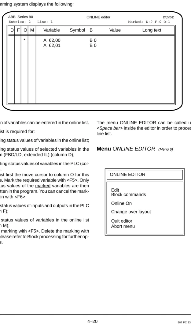
2.5.2 Error diagnosis with Advant Controller 31
Using the default online list, it is possible to perform error diagnosis for Advant Controller 31. This online list can be read in with function Read block. The online list (which is blank at the start) must be called for this purpose. The de-fault online list is read in with command <Ctrl>KR and by entering:
C:\ABB–SPS\AC31\PROJEKT\ONLINE
2.5.3 Intermediate flag, updating
If an output of a connection element (CE) is connected di-rectly to the input of another CE in the function block dia-gram, the programming and test system 907 PC 33 auto-matically assigns an intermediate flag for this connection.
Intermediate flag CE1
CE2
This intermediate flag is used several times in the pro-gram unless it is assigned “globally”. Owing to this multi-ple use, new values are continually assigned to the inter-mediate flag. In the case of some connection elements (CEs), the outputs and therefore the associated interme-diate flags are not updated in every program cycle.
Inter-mediate flags not updated by the CE1 can lead to faulty results with CE2. These faults are often difficult to recog-nize and find.
Remedy:
1. As a result, the outputs may not be directly connected with inputs of the subsequent CEs by lines in the case of CEs which do not update their outputs. In this case, the ”connection” to the next CE must be made by the explicit definition of a flag which is not in the range of the intermediate flags.
2. Alternatively, it is also possible to assign the interme-diate flags globally in the concerned partial plan by adding @GLO as a text at the start of the partial plan. Example:
No updating of the CE outputs; consequently, assign a flag explicitly. UST 0/1 MW 03,03 + MW 03,03 0 1
3
Configuration
____________________________________________________________________________________________
3.1
Project management (Project man.)
907 PC 331 displays the following after you call the main menu option Project man.:
Config. PC33 System functions DOS–Shell Print 1 Print 2 Print param. PLC commun. 1 PLC commun. 2 PLC commun. 3
ABB Series 90 Program module function selection EXAMPLE
1 Project data 2 Store project 3 Quit system 4 Modularization 5 Data backup 6 Data restore 7 Copy project Project man. Edit Library
1 Project data
907 PC 331 displays the following after calling menu option Project data:
Timeout: Project___: C:\ABB–SPS\AC31\PROJEKT\EXAMPLE
Library___: BIB\AC31
ABB Series 90 Project data EXAMPLE
PLC manufacturer: ABB PLC name_______: AC31
PLC type__________: Series 90 Responsible________: Project designation__: Project description__: Series 90 07KP62 Series 30, 40, 50 T320 V8 PLC version Last upda
The Project data menu contains information relevant to creation, processing and documentation of the user pro-gram.
Refer to 907 PC 33, chapter 5, for explanation of the pa-rameters which can be entered.
PLC type
The first step is to select the PLC type field with the cursor. Press the space bar to set and select the PLC type for which the user program is intended.
Series 90:
Make this selection when you program a 07 KR 91, 07 KT 92, 07 KT 93 or 07 KT 94.
Series 30,40,50:
Make this selection when you program a 07 KR 31, 07 KT 31, 07 CR 41, 07 CT 41, 07 KR 51 or 07 KT 51. 07 KP 62:
Make this selection when you program the communica-tion processor 07 KP 62 of the system ABB Procontic T200.
T320 V8:
Make this selection when you are processing a project which you have transferred with data transfer from 907
PC 32. This allows you to process and adapt the oper-ands which, for example, exceed the limits of Series 90. This activates the PLC type-dependent syntax monitor-ing facility for the program input. The relevant range limits of the operands of Series 30, 40, 50 and 90 are listed in Volume 4.
Note: The flag ranges (M and MW) are not limited by the Series 30, 40, 50 choice. The user has to take care not to use an invalid variable. Otherwise a transmis-sion error will occur when the program is sent to the central unit.
There is no control type-dependent monitoring for the in-put of the connection elements (CEs) in the FBD/LD edi-tor. All CEs contained in the CE library can be entered with every control type setting.
All further settings in the above screen display are ex-plained in the operating manual 907 PC 33, General Part. The choice of Series 30, 40, 50 selects the library with connection elements (CEs) available for these central units.
With the Series 30, 40, 50 the library of SER50 has to be chosen instead of the SER90 library. The library of SER50 contains all connection elements (CEs) avail-able for Series 30, 40, 50.
4
Online
____________________________________________________________________________________________
IMPORTANT:
Depending on the nature of the ONLINE functions, these have a direct influence on the PLC program and/or the I/O signals and thus on the process. Therefore, in all cases before running the function, make sure that personal injury and machine damage are impossible!
907 PC 331 provides a series of functions for commis-sioning and checking the PLC program. These include the main menu options PLC Commun. 1...3 and the ONLINE functions that can be called in the FBD/LD edi-tor, extended IL and the variable editor in a menu. To do this, your PC’s serial interface COM1 must be connected to the PLC’s serial interface with the cable 07 SK 90 R1, FPTN404948R0002 or 07 SK 50. You will find a further description of this cable in the system description of the Advant Controller 31, Volume 2 – Hardware.
You can use either the interface COM1 or COM2 of your PC for communication with the PLC. The interface is set in the main menu Config.PC33, COM port for prog.. When delivered, 907 PC 331 is set to the interface COM1.
4.1
PLC communication
Monitoring of the access path
If the programming system loads a PLC program in the PLC, the project name is also transferred to the PLC and stored.
The programming system automatically checks whether the access path leads to the required user program, be-fore each access operation to the PLC.
For this purpose, a check is conducted in order to estab-lish whether the project name in the PLC is the same as the project name in the programming system.
This ensures that the programming system is connected to the correct user program.
The user does not notice this check of the access path if the settings in the PLC are the same as the settings in the programming system. If differences are established dur-ing the check, a message is displayed, informdur-ing the op-erator what setting exists in the PLC and what setting ex-ists in the programming system. The user must then ac-knowledge whether the setting in the programming sys-tem is to be transferred to the PLC or not.
Message if the names do not correspond: ID in PLC:XXX / im System:YYY. Change? (Y/N) XXX = project name in the PLC
YYY = project name in the programming system Note on communication:
Communication between the PLC and the programming and test system is possible only if operating mode DEUTSCH is set on the PLC (default setting when deliv-ered). This also applies if working with the English pro-gramming software.
4.1.1
PLC communication 1
The programming system displays the following after call-ing menu option PLC commun. 1:
PLC commun. 1 PLC commun. 2 PLC commun. 3 Project man. Edit Library Print 1 Print 2 Print param. Config. PC33 System functions DOS–Shell
ABB Series 90 Program module function selection KUNDE
2 Receive program 3 Compare program 4 Delete program 5 Send constants 6 Receive constants 1 Send program 7 Compare constants 8 Start program 9 Abort program
1 Send program
The PLC program which exists in the form of an instruc-tion list is transferred if menu opinstruc-tion Send program is se-lected.
After transfer, you are prompted to decide whether the values of the constants (K, KW, KD) are also to be trans-ferred. If you answer “Yes”, the constants are transtrans-ferred. We must distinguish between two cases when transfer-ring programs to the PLC. We suggest the following pro-cedure:
Case 1:
The program in the PLC is in status “ABORTED”: – Transfer program to the PLC
– Transfer constants to the PLC – Save program in flash EPROM – Start program
Note:
Before starting the PLC program the system constants KW00,01 ... KW00,05 have to be set to 0 (= default) if the program has been modified in order to be on the safe side, so that all operand areas are initialized with 0 when start-ing the program. This makes sure that stored values of operands or historical values do not result in malfunc-tions. After program start the system constants KW00,01 ... KW00,05 can again be set to the values required for the application.
Case 2:
The program in the PLC is in status “RUNNING”: – Trans-fer program to the PLC
– Transfer constants to the PLC
– Enable changes in the PLC for processing – Save program in flash EPROM
Notes:
When the alterations are taken over, there is no PLC standstill time.
The user must exercise extreme care when making changes to a running PLC program, as the program changes immediately influence the running process with-out the possibility of tests. Programming errors can have grave results.
2 Receive program
The program is read from the PLC and stored in the gramming system if you select menu option Receive
pro-gram.
The start and end address of the program or program part to be read out must be specified. If the address of the end of the program PE is known, the program can be read out specifically up to this address. It is advisable to determine the address of the end of the program from the translated IL since entering the end address substantially speeds up the process of reading back from the PLC. If the PLC pro-gram is not read out as of word address 0, the range be-tween word address 0 and the entered start address is padded automatically with NOPs in the programming sys-tem.
3 Compare program
The program is read out of the PLC and compared to the current program stored in the programming system if you select menu option Compare porgram.
Modularized projects:
Calling up from the overall project level
In the case of modularized projects, the program compar-ison is conducted module–by–module. The modules are compared in the order in which they are listed in the mod-ularization editor.
Modularized projects:
Calling up from the program module level
In the case of modularized projects, program comparison takes place on a module–related basis if it is called up from the program module level. The PLC program is read out and compared starting at the address where the mo-dule begins up to the last address of the momo-dule. After the program has been read out of the controller, all instructions are checked for differences. Stating the word number, it is shown whether the command, operand or operand number differ.
The program comparison can be aborted after every de-tected difference. The number of differences found is dis-played at the end.
4 Delete program
The program is deleted from the PLC if you select menu option Delete program.
The programming system suggests ”0” as an initial word number and ”30583” as an end word number. Change the end word number to the maximum number of addresses supported by the PLC.
5 Send constants
The indirect constants (K, KW, KD) are transferred to the PLC if you select menu option Send constants.
If only values of constants are changed in the program-ming system and the program remains unchanged, it suf-fices to transfer these to the PLC with function “Send
con-stants”. In this case, it is not necessary to transfer the
pro-gram itself again to the PLC.
Function Send constants can be performed if the PLC program is in
– status “RUNNING” or in – status “ABORTED”.
6 Receive constants
The indirect constants (K, KW, KD) of the PLC program are read from the PLC and stored in the programming system in the variable list if you select menu option
Re-ceive constants.
The two binary constants (K 00,00 and K 00,01) are read out automatically. In the case of the word constants (KW) and the double word constants (KD), the required range must be specified. For example:
Word constants from: KW 00,00 to KW 01,00.
You can quit the function with <ESC>. When reading out, it is of no importance whether the constants to be read out are actually used in the program or not.
7 Compare constants
The constants (K, KW, KD) of the PLC program are read from the PLC and compared with those in the current proj-ect of the programming system if you selproj-ect menu option
Compare constants. Differences are displayed.
8 Start program
The PLC program is started if you select menu option
Start program. If there is a program in the Flash EPROM,
this program is copied to the user program RAM and started. The user must thus ensure that
– the most recent program version is always saved in the Flash EPROM or
– he works with an erased Flash EPROM during the test phase in which many program changes occur.
9 Abort program
The PLC program is aborted if you select menu option
Abort program. The related process outputs are set to the
4.1.2
PLC communication 2
The programming system displays the following after calling menu option PLC commun. 2:
Project man. Edit Library Print 1 Print 2 Print param. Config. PC33 System functions DOS–Shell
ABB Series 90 Program module function selection KUNDE
PLC commun. 1 PLC commun. 2 PLC commun. 3 1 Progr. ––> EPROM 2 Delete EPROM 3 Enable PLC mode 4 Cold start 5 Terminal emulation 1 Program ––> EPROM
When the menu point Progr. ––> EPROM is selected, the user program is transferred from the RAM memory of the PLC into the Flash EPROM. This safeguards the user program against power failure.
Whenever the PLC program is started up, the PLC pro-gram is first automatically transferred from the Flash EPROM to the RAM memory. The PLC program is then started from the RAM memory. Automatic transfer of the PLC program from the Flash EPROM to the RAM memory naturally only occurs when a PLC program is ac-tually present in the Flash EPROM.
2 Delete EPROM
Selecting the menu point Delete EPROM deletes the user program in the Flash EPROM of the PLC. The Flash EPROM should be deleted, for example, when you wish to prevent the program being overwritten in the RAM by the program version from the Flash EPROM at the start of the program (commissioning phase).
3 Enable PLC mode
The PLC mode (e.g. Stand–alone or Master) is defined by the value of the system constant KW 00,00. The default setting for the mode is ’Stand–alone mode’ (KW 00,00 = –2).
A change of the PLC mode is performed in three steps: 1. Change system constant KW 00,00 and transfer to
the PLC
2. Save the PLC program in the Flash EPROM (this saves the changed system constant KW 00,00 in the Flash EPROM)
3. Activate the new PLC mode by:
– calling menu option Enable PLC mode or – switching the power off and back on again or – calling menu option Cold start
If the RUN/STOP switch is set to RUN, the PLC program is also started with Enable PLC mode.
4 Cold start
A cold start is performed on the PLC if you call menu op-tion Cold start.
A cold start sets the PLC to its initial state (condition as delivered). All RAMs are tested and erased. If there is a program in the Flash EPROM, this program is transferred to the program RAM. The modes configured in this pro-gram are set on the PLC.
5 Terminal emulation
The programming and test system emulates a terminal if you select menu option Terminal emulation.
The PLC has integrated programming, test and monitor functions which provide the user with access to all PLC capabilities via a terminal. Certain PLC functions which cannot be addressed directly by the programming system can be used with the aid of Terminal emulation. The possi-ble functions within terminal emulation are described in the System description Advant Controller 31, Section 7. Quiiting Terminal–Emulation:
You can quit terminal emulation again by pressing key <ESC>.
4.1.3
PLC communication 3
The programming system displays the following after calling menu option PLC commun. 3:
Projekt man. Edit Library Print 1 Print 2 Print param. PLC commun. 1 PLC commun. 2 PLC commun. 3 Config. PC33 System functions DOS–Shell
ABB Serie 90 Program module function selection KUNDE
1 Trace on 2 Trace off 3 Trace status 4 I/O test on 5 I/O test off 6 Display PLC status 7 Free progr. space
Trace mode
In Trace mode, the PLC notes in a trace register the user program address last executed. After a system crash, this tells you at what point in the program the crash occurred. Trace mode increases the execution time of the user pro-gram. The contents of the trace register are retained even in the following cases:
– in the case of a warm start (Enable PLC mode) – after power–up, if the PLC is equipped with a back-up
battery.
Not available in Series 30, 40, 50.
1 Trace on
Trace mode is activated on the PLC if you select menu op-tion Trace on.
2 Trace off
Trace mode is deactivated on the PLC if you select menu option Trace off.
3 Trace status
The contents of the trace register are displayed if you se-lect menu option Trace status. The trace register contains the last program address executed.
4 I/O test on
Operating mode I/O test is activated if you select menu option I/O test on.
In operating mode I/O test, the user can check the cor-rectness of the wiring of his I/O signals from the PLC pro-gram through to the process.
The PLC program is not executed after start in operating mode I/O test. Only the I/O signals planned in the pro-gram are operated, i.e. the input signals are read in and the output signals are output. However, the output signals are output only if they have been set by the user, e.g. by forcing.
By actuating limit switches etc., it is possible to check whether these signals are arriving in the PLC with the de-clared I/O designations. By specifically overwriting or
forcing outputs, you can check whether the signals issued
are arriving at the correct point in the process.
The values of the I/O operands of interest in the PLC can be displayed with function Status display in online mode. Command I/O test on can be executed even with the pro-gram running. The operating mode is then activated at the start of the next program cycle.
Not available in Series 30, 40, 50.
5 I/O test off
Operating mode I/O test is deactivated by selecting menu option I/O test off, i.e. the user program is executed nor-mally again as of this point. It is practical to abort the pro-gram before activating the I/O test.
6 Display PLC status
The entire status of the PLC is displayed as follows if you select menu option Display PLC status:
– Program identification (project name) – Cycle time in ms
– Program status – Active test functions
– Contents of the TRACE register – Error messages
– Capacity utilization
7 Free program space
The number of program memory words still free in the PLC is calculated if you select menu option Free progr.
space. The program memory in the PLC is checked from
the end for NOPs. The number of NOPs found is then dis-played.
4.1.4
PLC communication from FBD/LD
and extended IL
Besides PLC communication directly from the menu in-terface, it is also possible to communicate with the PLC from the FBD/LD or the extended IL. When you press the space bar or the right mouse button, a window is pulled down containing an overview of the functions available in the FBD/LD or in the extended IL. You will see the follow-ing window after you select function
TRANSLATE/TRAN-SFER: TRANSLATE/TRANSMIT Translate changes Translate complete Translate/transmit changes Send changes
Reactivate old program Send program Compare program Send constants Compare contstants Progr. ––> EPROM Delete EPROM Display transl. IL Troubleshooting Level higher
Note on how to carry out changes in a program:
If changes are made in a program, they have to be trans-lated and send before leaving the editor.
Fast translation and transmission of the program
A fast procedure can be used for translating the FBD/LD or extended IL, namely ”Translate changes”. However, a precondition is that the entire program has already been translated once.
Sending the translated IL to the PLC can also be acceler-ated by ”Send changes”. However, a precondition is that the entire program has already been sent once.
With ”Send changes”, whole partial plans (those in which changes have been made) are sent.
In addition, it is also possible to transfer program changes or a complete program online, i.e. with the PLC running. In order to be able to use all possibilities, a few instruc-tions must be observed. These are listed in the table be-low.
Type of change in FBD/LD or extended IL Guidelines Change variable e.g. E0,0 to M0,0 Swap CE e.g. & / to
Set or delete inversion Add CE
Delete CE (no CEs with histor-ical values; see CE description in Volume 7)
Split, move, insert or append segment plan
Insert block into already existing segment plan (with block function <Ctrl>–K–R), block does not fit in the current SP
Delete whole segment plan
● ● ● ● ● ● ● ● Modify sequence of segment plans ●
Instructions for ’Translate changes’ and ’Send changes’
Translate changes is possible, even with changes in several
segment plans.
Send changes is possible, as long as no segment plans were added.
Translate changes is possible, even with changes in several
segment plans.
Send changes is not possible. The entire program must be
transferred with Send program.
Translate changes is not necessary (the programming software notes
the deleted segment plan and does not send it to the PLC). However, the entire program must be transferred with Send program.
Note: It is possible to send changes both in the ’Program aborted’ state and in the ’Program running’
state.
Change text constant e.g. #”Text1 to #”Text2
●
Double CE connection
●
Copy block
●
Read in block with <CTRL–KR> (block fits in the current SP)
●
Copy segment plan
●
Read in block in the segment plan management
● Note on using <CTRL>–Z
If you just want to look at a variable with symbol and long text but not change it, please use the key combination <CTRL>–P. This tells 907 PC 331 that no changes were made and also does not request the translation. The function can also be called up in online mode. Shift segment plan
●
Change a text constant with <CTRL>–Z or in the variable edi-tor
● Translate changes is not possible. Everything must be translated.
The entire program must be transferred with Send program.
Translate changes is possible, even with changes in several
segment plans.
Send changes is possible.
Change a variable with <CTRL–Z>
●
Change one or more variables in the variable editor
Further notes
● Function blocks with historical values may only be
add-ed or omittadd-ed at the end of the program.
● Any changes to indirect constants are permitted. This
includes also changing the cycle time. If system con-stants are modified, take care of Chap. 2.1, ’System constants’.
Send changes is not possible if
● a new program module was inserted or deleted in the
case of modularized projects
● the order of the program modules was changed in the
case of modularized projects.
Translate changes
The program changes made in the FBD/LD or in the ex-tended IL are translated if you select menu option
Trans-late changes. The time taken for translation is reduced
since the entire program does not need to be translated.
Translate changes can be selected almost always. In the
case of changes which require translation of the entire program, the programming system issues a correspond-ing message.
Translate complete
The entire program is translated if you select menu option
Translate complete.
Translate and transmit changes <Alt>–1
The program changes performed in the FBD/LD or in the extended IL are translated and then transferred to the PLC if you select menu option Translate/transmit
changes. The time taken for translation and transfer is
re-duced since the entire program does not need to be trans-lated and transferred. Please refer to Send changes for further information.
After transfer, you are prompted to decide whether the values of the constants (K, KW, KD) are also to be trans-ferred. If you answer Yes, this is then done.
Send changes <Alt>–2
The program changes performed in the programming system are transferred to the PLC if you select menu op-tion Send changes. The time taken for transfer is reduced because the entire program does not need to be trans-ferred.
The Flash EPROM is automatically deleted beforehand. This prevents the program in the RAM being overwritten by the old program version from the Flash EPROM during the next program start (commissioning phase). After commissioning is completed, the PLC program should al-ways be stored in the Flash EPROM.
This menu point can only be used if the entire program has already been transferred to the PLC once and if pro-gram changes were subsequently made in the propro-gram- program-ming system. Program changes exist when changes have been made and translated with Translate changes in the FBD/LD or in the extended IL.
You can use function Send changes if the PLC program is in
– status “RUNNING” or in – status “ABORTED”.
A distinction must be made between two cases when transferring programs to the PLC. We suggest the follow-ing procedure for this:
Case 1:
The program in the PLC is in status “ABORTED”: – Transfer program changes to the PLC
– Transfer constants to the PLC – Save program in Flash EPROM – Start program
Note:
Before starting the PLC program the system constants KW00,01 ... KW00,05 have to be set to 0 (= default) if the program has been modified in order to be on the safe side, so that all operand areas are initialized with 0 when start-ing the program. This makes sure that stored values of operands or historical values do not result in malfunc-tions. After program start the system constants KW00,01 ... KW00,05 can again be set to the values required for the application.
Case 2:
The program in the PLC is in status “RUNNING”: – Trans-fer program changes to the PLC
– Transfer constants to the PLC
– Enable changes in the PLC for processing – Save program in Flash EPROM
Notes:
When the alterations are taken over, there is no PLC standstill time.
The user must exercise extreme care when making changes to a running PLC program, as the program changes immediately influence the running process with-out the possibility of tests. Programming errors can have grave results.
Reactivate old program <Alt>–8 Not available in Series 30, 40, 50
The changes made and enabled on a running PLC pro-gram are cancelled again by the PLC if you select menu option Reactivate old program. The PLC then reesta-blishes the program status as it existed before transfer of the changes.
The PLC requires approximately 1 ms to reactivate the old program status.
You can use the command if you recognize that the pro-gram changes made on the running PLC propro-gram are not having the required effect.
Note:
The above–described functionality runs only in the PLC, i.e. the program changes made and stored in the pro-gramming system are not affected by this. The user him-self must ensure that the changes are cancelled again in the programming system so that the program in the PLC is the same as the program in the programming system again.
Send programm <Alt>–3
The PLC program which exists in the form of an instruc-tion list is transferred completely if you select menu opinstruc-tion
Send program.
After transfer, the system prompts you to decide whether the values of the constants (K, KW, KD) are also to be transferred. If you answer Yes, this is then done. We must distinguish between two cases when transfer-ring programs to the PLC. We suggest the following pro-cedure for this:
Case 1:
The program in the PLC is in status “ABORTED”: – Transfer program to the PLC
– Transfer constants to the PLC – Save program in Flash EPROM – Start program
Note:
Before starting the PLC program the system constants KW00,01 ... KW00,05 have to be set to 0 (= default) if the program has been modified in order to be on the safe side, so that all operand areas are initialized with 0 when start-ing the program. This makes sure that stored values of operands or historical values do not result in malfunc-tions. After program start the system constants KW00,01 ... KW00,05 can again be set to the values required for the application.
Case 2:
The program in the PLC is in status “RUNNING”: – Trans-fer program to the PLC
– Transfer constants to the PLC
– Enable changes in the PLC for processing – Save program in flash EPROM
Notes:
When the alterations are taken over, there is no PLC standstill time.
The user must exercise extreme care when making changes to a running PLC program, as the program changes immediately influence the running process with-out the possibility of tests. Programming errors can have grave results.
Compare program <Alt>–4
The program is read out of the PLC and compared with the current program stored in the programming system if you select menu option Compare program.
In the case of modularized projects, program compari-sons are made on a module–related basis. The PLC pro-gram is read out as from the address at which the module starts and is compared up to the address at which the mo-dule ends.
After the program has been read from the PLC, all instruc-tions are checked for differences. The system displays whether command, operand or operand number differ, specifying the word number.
The program comparison can be aborted after every de-tected difference. The number of differences found is dis-played at the end.
The help program ”Compare” offers a further possibility for comparing PLC projects. It is described in chapter 5.
Send constants <Alt>–6
The indirect constants (K, KW, KD) are transferred to the PLC if you select menu option Send constants.
If only values of constants have changed in the program-ming system and the program remains unchanged, it suf-fices to transfer these to the PLC with Send constants. The program itself does not need to be transferred to the PLC again.
You can perform function Send constants if the program is in
– status “RUNNING” or in
– status “ABORTED”.
Compare constants <Alt>–7
The constants (K, KW, KD) of the PLC program are read from the PLC and compared with those in the current proj-ect of the programming system if you selproj-ect menu option
Compare constants. Differences are displayed.
Program ––> EPROM
The user program is transferred from the RAM of the PLC to the Flash EPROM if you select menu option Progr. ––>
EPROM. This thus safeguards the user program against
Each time the PLC program is started, the PLC program is first transferred automatically from the Flash EPROM to the RAM. The PLC program in the RAM is then started. Automatic transfer of the PLC program from the Flash EPROM to the RAM is performed, of course, only if there is actually a PLC program in the Flash EPROM.
Delete EPROM
The user program in the Flash EPROM of the PLC is de-leted if you select menu option Delete EPROM. The Flash EPROM should be erased for instance if you wish to pre-vent the program in the RAM being overwritten by the pro-gram version from the Flash EPROM when starting the program (commissioning phase).
4.2
Test
Extensive operator control and test functions are avail-able for testing the PLC program in online mode. These operator control and test functions can be used
● in the FBD/LD ● in the extended IL ● in the variable list ● in the online list.
In addition, online information such as program status, variable status and breakpoint addresses is displayed on the monitor.
Status information is designated or abbreviated as fol-lows:
Running Program execution is running. Aborted Program execution is aborted; the
outputs are set to “0”.
Stopped Program execution is stopped;
the outputs retain their last value. On breakpoint Program execution has stopped since Single step (ES) or Single cycle (EZ) is active or since a breakpoint has been reached.
EZ Single cycle active
ES Single step active
On breakpoint Breakpoint set. The breakpoint address, consisting of module number and word number, is dis-played when a breakpoint is re-ached.
BV Breakpoint pursuit on
FO Forcing active
Variable sta outp Status of selected variables on
The following functions are not available in the Se-ries 30, 40, 50:
– Stop
– On breakpoint
– EZ
Online
Project: \EXAMPLE\Program example SP No: 02 ABS TX:00 TY:021
Program example E 62,00 E 62,01 E 62,02 KD 01,00 ASV 0–T ZD / Q
Your Program should then ======================= ONLINE Online On/Off Online functions Display format Collect Online list Breakpoint list Level higher
The online test is activated and deactivated by selecting menu option Online On/Off. The menu is displayed after you press the space bar or the right mouse button. You can select the required menu option with the Enter key or the left mouse button.
The online mode is possible:
in the function block diagram/ladder diagr. FBD/LD in the extended instruction list (extended IL) in the variable list
in the online list
Notes:
Display of variable states when the program is aborted: Inputs: As the central units use the process image,
the last states of the inputs retain in the input image. If therefore the program is aborted and after that, the states of the inputs change, then these states cannot be displayed as the process image is not updated.
Outputs: When the program is aborted, the real outputs are set to 0. However the outputs in the pro-cess image still have their old values. That means that the ’old’ states of the outputs are displayed in 907 PC 331. Only after a new start of the PLC program the process image will be updated.
ONLINE FUNCTIONS Start Abort Stop Continue Abs./Sym. Level higher Bit/word Single cycle Single step Breakpoint Status Overwrite Jog
Stat. sel. var. On/Off
BREAKPOINT Set single Set all Abs./Sym. Level higher Bit/word Jog
Stat. sel. var. On/Off
STATUS
Variable status Status trigger on var. Status trigger time
Abs./Sym. Level higher Bit/word Jog
Stat. sel. var. On/Off Edit stat. sel. var.
OVERWRITE
Edit overwrite list Overwrite all
Level higher Jog
Stat. sel. var. On/Off
ABB Series 90 ONLINE editor KUNDE
Variable Symbol B A A A A Va
Return to the function menu of the editor from which the ON-LINE FUNCTIONS were called.
Return to the editor from which the online list was se-lected, e.g. FBD/LD.
Menu overview Online functions
Force
FORCE
Edit force list
Abs./Sym. Level higher Bit/word Jog
Stat. sel. var. On/Off Display force values Disable forcing single
Edit BP list Overwrite single Display Delete single Delete all BP pursuit on/off Accept status Force single Force all Disable forcing all
Entries: 4 Line: 0 Marked:D:0 F:0 0:0
ONLINE EDITOR Menu 6
ONLINE Menu 7
Edit
Block commands Online on
Change over layout Quit editor Abort menu Start Abort Stop Continue Single cycle on/off Single step on/off Status
Overwrite Force Jog
Stat. sel. var. On/Off Online off Quit editor Abort menu Menu 1 Menu 2 Menu 3 Menu 4 Menu 5
Collect for BP list
Collect for force mode
Collect for sel. var.
Collect for overwrite Freeze status display
(only FBD/LD) (only FBD/LD) on/off on/off (only FBD/LD) (only FBD/LD) (only FBD/LD) (only FBD/LD) (only FBD/LD) (only FBD/LD) Bit/word (only FBD/LD) Abs./Sym. (only FBD/LD) D F O M
ONLINE functions
It is possible to call the required online functions by select-ing the correspondselect-ing menu option durselect-ing online test.
Menu ONLINE FUNCTIONS
(Menu 1)ONLINE FUNCTIONS Start Abort Stop Continue Abs./Sym. (only FBD/LD) Level higher Bit/word (only FBD/LD) Single cycle on/off Single step on/off Breakpoint Status Overwrite Jog
Stat. sel. var. On/Off Force
––> ––> ––> ––>
Start program, <Alt>–S
The PLC program is started if you select menu option
Start or if you press hotkey <Alt>–S.
You can start the program only if the program is in status
Aborted and the RUN/STOP switch is set to position
RUN.
Timers which have been started continue to run indepen-dently of the status of the user program in the operating system of the PLC. They are aborted only by a warm start or a cold start.
Abort program, <Alt>–A
The PLC program is aborted if you select menu option
Abort or if you press hotkey <Alt>–A. Execution of the
user program is aborted at the end of the program. The related process outputs are set to the value 0.
You can abort the program only if the program is in status
Running or Stopped.
Timers which have been started continue to run indepen-dently of the status of the user program in the operating system of the PLC. They are aborted only by a warm start or a cold start.
Stop program, <Alt>–H
The PLC program is stopped if you select menu option
Stop or if you press hotkey <Alt>–H. Execution of the user
program is stopped at the end of the program. The flags and the process outputs retain their values.
You can stop the program only if the program is in status
Running.
Timers which have been started continue to run indepen-dently of the status of the user program in the operating system of the PLC. They are aborted only by a warm start or a cold start.
Not available in Series 30, 40, 50. Continue program, <Alt>–C
The PLC program is continued if you select menu option
Continue or if you enter command <Alt>–C.
You can continue the program only if the program is in sta-tus Stopped.
Timers which have been started continue to run indepen-dently of the status of the user program in the operating system of the PLC. They are aborted only by a warm start or a cold start.
Not available in Series 30, 40, 50. Single cycle On/Off, Z
Operating mode Single cycle is activated or deactivated if you select menu option Single cycle or if you press hotkey Z.
Execution of the PLC program is interrupted at the end of the program in operating mode Single cycle. The flags and process outputs retain their values.
Advancing by one program cycle: “Jog”.
A further program cycle is executed in each case with function “Jog”. Timers which have been started continue to run independently of the status of the user program in the operating system of the PLC. They are aborted only by a warm start or a cold start.
Not available in Series 30, 40, 50. Single step On/Off, S
Operating mode Single step is activated or deactivated in the PLC program if you select menu option Single step or if you press hotkey S.
Execution of the PLC program is interrupted after each program step in operating mode Single step.
A program step extends in each case:
● through to the end of the next function block, ● through to the next assignment,
● through to the next “right bracket”.
The flags and process outputs retain the values assigned to them in the PLC program.
Advancing by one program step: “Jog”.
A further program step is executed in each case with func-tion “Jog”.