Using an UAV for Testing an Autonomous Terrain-based
Optical Navigation System for Lunar Landing
Nikolaus Ammann German Aerospace Center (DLR)
Institute of Flight Systems 38108 Braunschweig, Germany
+49 531 295-2922 [email protected]
Stephan Theil
German Aerospace Center (DLR) Institute of Space Systems
28359 Bremen, Germany +49 421 24420-1113 [email protected]
Abstract—This paper presents the application of a rotary wing Unmanned Aerial Vehicle (UAV) as a testbed for the optical nav-igation system developed in the project “Autonomous Terrain-based Optical Navigation” (ATON) of the German Aerospace Center (DLR). Since using optical sensor data in navigation sys-tems for exploration missions is a promising technology, many projects have focused on the development of such navigation systems. To allow autonomous operation of these developed navigation technologies in the targeted environment extensive testing is necessary for achieving an appropriate grade of reli-ability. A review of the current approaches for true-scale testing of optical navigation systems for lunar or planetary landing missions is conducted, and the proposed testing methodology is motivated. The paper describes the development steps necessary to conduct closed-loop real-time flight tests using a rotary wing UAV. This includes the sensor configuration, preparation of the flight test area and ground truth generation. Finally, the result-ing navigation performance of the ATON navigation system in the closed-loop real-time flight tests is presented.
T
ABLE OFC
ONTENTS1. INTRODUCTION. . . 1
2. RELATEDWORK . . . 3
3. FLIGHTTESTSETUP. . . 4
4. FLIGHTTESTRESULTS . . . 6
5. CONCLUSION. . . 6
ACKNOWLEDGMENTS. . . 7
REFERENCES. . . 8
BIOGRAPHY. . . 9
1. I
NTRODUCTIONFuture space missions include exploration tasks such as re-search of local phenomena, experiments on the utilization of resources and the construction of bases on different celestial bodies like Mars, Moon and asteroids. To perform these tasks successfully, autonomous, precise, and safe landing on these bodies is required. Therefore future spacecraft and landers have to be equipped with adequate navigation systems. These navigation systems have to be able to estimate the position and attitude of the spacecraft autonomously in an unknown environment and without any external signals like Global Navigation Satellite Systems (GNSS) or a communi-cation link. Using optical systems as an input for the state estimation is a promising technology. The optical measure-ments can be acquired with small delay and they are fully independent on external man-made signals. Introducing this raw or preprocessed optical sensor data to the state estimator
978-1-5386-2014-4/18/$31.00©2018 IEEE Moon P ark ing o rb it D es ce ntO rb it Powered Descent Landing DOI PDI Sun
Figure 1. Sketch of the lunar landing scenario starting with a circular parking orbit. With the Descent Orbit
Injection (DOI) maneuver the spacecraft enters the Descent Orbit (DO). The Powered Descent (PD) is the last phase of the landing and starts with the firing of the
engine at the Powered Descent Injection (PDI).
can significantly improve the position and attitude estimate by performing terrain-based optical navigation.
Besides the development of technologies for optical naviga-tion which could be applicable to various space exploranaviga-tion missions, one major goal of the project “Autonomous Terrain-based Optical Navigation” (ATON) of the German Aerospace Center (DLR) is the testing of the developed navigation system to improve its maturity.
At the end of this introduction a short description of the ATON project is given to provide the context of terrain-based optical navigation and the application to lunar landing scenarios. This is followed by a summary of related work regarding the testing of navigation systems for lunar or plan-etary landing in section 2. This is followed by a description of the preparations necessary to emulate the lunar landing scenario in a flight test. This includes the unmanned research helicopter, the sensor configuration of the helicopter’s pay-load, and the preparation of the test site. In section 4 the results of the most recent flight test are presented. Finally, the paper closes with a conclusion in section 5.
DLR’s project ATON
In the following, a short description of the ATON project is given. As mentioned earlier, the goal of the ATON project is the development of technologies for terrain-based optical navigation which should be capable to determine the naviga-tion solunaviga-tion from beginning of the landing maneuver at the Descent Orbit Injection (DOI) down to the touchdown at the landing site. The description focuses on the lunar landing scenario, the sensor configuration and the software architec-ture. A more detailed description of the project including the motivation, the scenario and mission definitions, and earlier performed tests and verifications can be found in [1].
Lunar Landing Scenario—Figure 1 sketches a lunar landing scenario with a circular parking orbit.
At the DOI, the navigation accuracy corresponds to the capa-bility of the ground station network. During the coasting in the Descent Orbit (DO), the landmark navigation system shall provide several measurements with an accuracy of 1% of current altitude. This enables the state estimator to determine the position at Powered Descent Injection (PDI) within 100m. During the Powered Descent (PD), the optical navigation system will perform altimeter and velocimeter functions. Due to the lack of position measurements the navigation error will grow during this period. The task of the navigation system is to keep the propagation stable and the error growth small. From the beginning visibility of the landing site, the 3D imag-ing system will start to take measurements. The resultimag-ing data will possess an initial resolution in the order of 50m and continuously grow during the descent. The 3D data will be compared with an onboard 3D map of the landing site, gaining a navigation knowledge in the order of 50m. The purpose of the 3D imaging system is also to deliver the necessary data for the evaluation of the landing area. When a safe landing site is found, the guidance, navigation and control (GNC) system must be able to place the lander inside the safe area. The size of the safe area is assumed to be in the order of three times the diameter of the lander. Thus, the allowed landing error is in the order of one lander diameter. The navigation requirement for the landing is therefore set to 2m. This should be possible when considering the 3D data requirement at the late stage of the landing. The needed 3D resolution is in the order of 15cm per pixel. This data will become available in an altitude of≈400m.
Sensor Configuration—To provide the needed measurements for the above described scenario the following sensors are included in the navigation system:
• Inertial Measurement Unit (IMU): The inertial measure-ment unit provides measuremeasure-ments of the acceleration and angular rate.
• 2D Imaging Sensor: A monocular monochrome camera taking images of the celestial body and terrain is used as the navigation camera.
• Laser Altimeter: The laser altimeter measures the distance to the ground along its line of sight.
• Star Tracker: For providing inertial attitude information a star tracker camera is included.
• 3D Imaging Sensor: A Flash LIDAR providing a 3D point cloud for navigation and hazard avoidance.
For the analyses of different image processing algorithms and methods, the parameters of the sensors must be fixed. There-fore, the presented set of parameters is used as a baseline
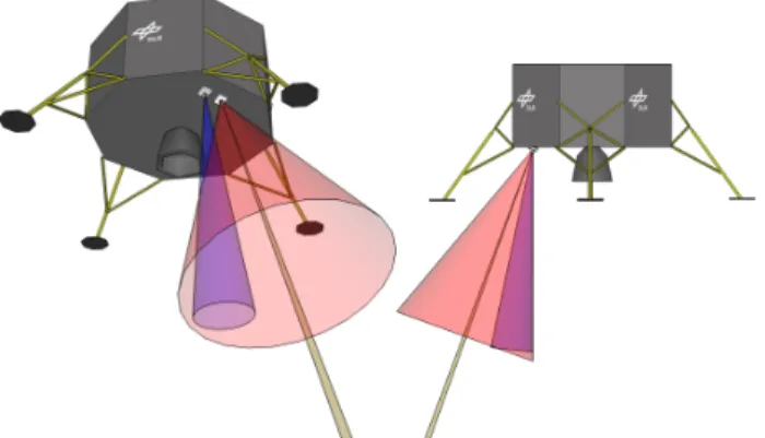
for the further development. For each sensor the specific parameters and the relative orientation are given. A detailed discussion regarding the sensor parameters can also be found in [1]. The sensor setup of the sensors is illustrated in Fig. 2. The IMU used should be of equal quality like in the study in [2]. It is mounted perfectly aligned with the body coordinate system of the vehicle.
Tables 1 and 2 show the baseline parameters for the navi-gation camera and the flash LIDAR, respectively. The pa-rameters have been selected based on the review of currently developed and planned hardware [3].
Table 1. Camera specifications as used in the project ATON
Resolution [px] 1024×1024 Frame rate [1/s] 30 FOV [deg] 40×40
Table 2. LIDAR specifications as used in the project ATON Resolution [px] 400×400 Frame rate [1/s] 1 FOV [deg] 12×12 Range [m] 1 - 1000 Noise [m] 0.02
The navigation camera and LIDAR are mounted in a way that the edge of the field of view for camera and LIDAR is on one side the x-direction of the body-fixed frame (down direction when the lander is vertical upright, e.g., on ground, or forward direction when the main engine is horizontally aligned in PD). All optical sensors are mounted on the side which faces the ground during the almost horizontal flight in the first phase of the PD.
The laser altimeter is aligned with the navigation camera. Therefore, the distance measurement corresponds to the cen-ter of the camera image.
The star tracker used is assumed to be also of equal quality like in the study in [2]. It should be mounted with its boresight close to the pitch axis of the vehicle. See [1] for more details.
Software Architecture—The ATON software consists of sev-eral processing modules. These modules are encapsulated in tasks which are executed in parallel. The scheduling of the tasks and the inter-module communication are managed by DLR’s data flow-oriented “Tasking Framework” [4]. For the development of the ATON software a model-driven software development methodology was used. An SysML/UML2
model of the ATON software was used to automatically gen-erate the source code for data types, communication, module interfaces, and serialization code for the telemetry [5]. Since the output of the system shall be the navigation state vector, a mandatory element is a navigation filter which com-bines and fuses all sensor measurements and preprocessed
2The Systems Modeling Language (SysML) and the Unified Modeling Language (UML) are general-purpose modeling languages for system- and software engineering applications.
Figure 2. Sensor configuration for ATON: Camera (red), Laser Altimeter (green),LIDAR (blue)
data to a navigation solution. This is complemented with further modules for processing the optical sensor data:
• Crater Navigation: The Crater Navigation module detects impact craters in the camera images, and matches each crater detection to an element from a static crater catalog referenced in Moon-fixed coordinates. From that correspondence, a Moon-fixed position can be computed [6], [7].
• Shadow Matching: The Shadow Matching module also provides a Moon-fixed position. The algorithm uses shadows on the lunar surface as landmarks as in [8]. It creates descrip-tors for each shadow extracted from the camera image. These shadow descriptors are matched with reference descriptors which have been computed prior to the flight. In a final step, the matching result is used to compute an estimate of the absolute pose.
• Feature Tracker: The Shadow Matching module is used to extract and track image features over the camera sequence. The underlying algorithim is theKanade Lucas Tomasi(KLT) tracker. The tracker is based on feature extraction [9] and fea-ture tracking [10]. This algorithm allows tracking with sub-pixel accuracy for sharp textures. The 2D sub-pixel coordinates of these image features are output to the Navigation Filter module.
• 3D Matching: The 3D Matching module provides a Moon-fixed position. It is based on the Iterative Closest Point (ICP) algorithm [11], [12] which can determine the relative transformation between two 3D point clouds. These two point clouds are: The 3D point cloud from the flash LIDAR and a reference point cloud generated on-ground from a Digital Elevation Model (DEM) of the landing site.
• Navigation Filter: The Navigation Filter module combines
and fuses the raw measurements from the sensors (IMU, altimeter, and star tracker), and the preprocessed data from the described modules to a navigation solution. It is based on high-rate strap-down computation and a low-rate error-state Unscented Kalman Filter (UKF) [13], [14]. The strap-down algorithm uses the IMU measurements to propagate the total navigation solution forward in time for each measurement. The low rate UKF estimates the sensor errors of the IMU, and the accumulated error of the strap-down algorithm and corrects the propagated navigation solution.
2. R
ELATEDW
ORKUsing optical sensor data in navigation systems for explo-ration missions is a promising technology [1]. Therefore,
many projects have focused on the development of such navigation systems. There have been efforts for maturing sensor technologies such as scanning lidars, and cameras, as well as, applying these sensors in optical navigation sys-tems of space exploration missions [1], [15]. To allow au-tonomous operation of these developed navigation technolo-gies in the targeted environment extensive testing is necessary for achieving an appropriate grade of reliability.
Since testing the navigation systems in the targeted environ-ment would be unacceptably expensive, other testing method-ologies have to be used.
The most fundamental testing methodology applicable for testing algorithms and methods for optical navigation is to setup a software simulation environment. These simulation environments can get very detailed and complex to produce physically plausible synthetic sensor data based on actual DEMs of the target celestial body [16], [17]. But all simu-lations are limited to synthetic sensor data.
To increase the maturity of the developed technologies the setup for testing requires an increasing complexity, with actual sensors in the loop. But different kind of sensors require different kind of on-ground testing setups to verify their function and the overall performance of the navigation system.
Since cameras are not significantly sensitive to scaling, apart from focus related effects, the scenario and scenes can be scaled down to test and verify subsequent image processing techniques. An example for a downscaled on-ground testing facility is DLR’s Testbed for Robotic Optical Navigation
(TRON). It allows qualification of hardware and software to
Technology Readiness Levels(TRL) of up to 6 [18], [19]. The distance measured by a laser altimeter or a LIDAR is not scaled due to the measurement principle. The measurement could be corrected by the scale factor, but this would also scale the noise. Therefore, an operational testing with these sensors is not very useful in a downscaled scene. The
Test Environment for Navigation Systems On airfield Runway
(TENSOR) facility is an example for a true-scale testing facility for ranging sensors, and (flash) lidar sensors [19]. When developing integrated navigation systems combining all these optical sensors with other sensors e.g. inertial sensors, all the limitations for testing are also combined. Hence, an integrated navigation system can only be fully tested in a true-scale scenario.
When it comes to true-scale testing of optical navigation systems for landing on celestial bodies, several different approaches have been published. The testing facilities used range from ground based rocket sledges [20] over flight tests using manned [21] or unmanned helicopters [22], and terrestrial rockets [23], [24] up to flight tests using an actual prototype of a planetary lander, calledMorpheus Lander[25]. Of course, testing an optical navigation system for planetary landing mounted to a prototype of a planetary lander is the most realistic way to test such a system on Earth. But using a rocket or a rocket propelled lander comes with an increase of complexity and a higher risk in case of an accident compared to a helicopter flight test. Therefore, we decided to use an unmanned helicopter for testing the developed optical navigation system.
Using an unmanned helicopter allows flight trajectories sim-ilar to planetary lander trajectories in the last phase prior to touchdown. Additionally, this allows the integration of the navigation system into the control loop of the helicopter. This enables closed-loop testing of the navigation system. A similar testing facility called European Precision Land-ing GNC Test Facility (PLGTF) has been published by Guizzo et. al in 2007 [22]. But no updates regarding this testing facility have been published since. Therefore, our approach on how to use an UAV for testing an autonomous terrain-based optical navigation system for lunar landing is presented in this paper. The objective of the flight test was to demonstrate the real-time closed-loop operation of the ATON navigation system in a lunar landing scenario.
3. F
LIGHTT
ESTS
ETUPThe objective of the flight test was the demonstration of the real-time closed-loop operation of the ATON navigation system in a lunar landing scenario. The basic test concept was to fly a navigation sensor suite along a predefined ref-erence trajectory over the flight test area. The ground was prepared with artificial crater-like targets, that were mapped with respect to an Earth-fixed coordinate frame. The ATON navigation system provided a navigation solution, which was used for the guidance and control systems of the unmanned helicopter.
Several other development steps had to be done, before conducting the flight tests. First, the integration of the specific flight test hardware into the unmanned helicopter had to be completed. This included hardware and software developments, like production of the payload rack and sensor brackets as well as implementation, integration, and testing of the sensor drivers and software interfaces. Furthermore, the development included the design and production of targets resembling craters as well as the accurate mapping of the crater targets.
This section presents the unmanned helicopter used for the flight tests, the flight test trajectory, the results of the payload development, and the preparation of flight test area.
Autonomous Rotorcraft Testbed for Intelligent Systems
The unmanned research helicopter superARTIS, which has been used for the flight tests, is part of DLR’sAutonomous Rotorcraft Testbed for Intelligent Systems (ARTIS) test-ing facility. This facility provides DLR with an ideal testbed for state-of-the-art research in intelligent functions for UAVs [26], [27]. It is extended by software-in-the-loop and hardware-in-the-loop simulation environments allowing extensive testing of the flight software prior to the actual flight test and therefore allowing the safe operation of the UAVs. Being a testing facility, the ARTIS UAVs follow a mod-ular avionics concept. This enables easy reconfigurability for a variety of flight computers, payloads, and data links. Furthermore, also the flight software follows the modular concept. With that modularization, the flight control, the guidance, and the navigation processes run as separated tasks communicating through a middleware. This allows an easy reconfiguration of the flight software, and a distribution of the tasks over multiple flight computers.
Based on the described characteristics the ARTIS is well suited for not only carrying the optical navigation system
Figure 3. DLR’s unmanned research helicopter superARTIS
Table 3. superARTIS - Technical specifications superARTIS Rotor diameter 2 x 2,82 m Engine 10.6 kW turbine Rotor RPM 950 Dimension l/w/h 2,32 m x 0,7 m x 0,92 m Empty weight 42 kg Max payload 45 kg MTOW 87 kg
Max flight time 150 min Max service ceiling 3000 m above MSL
Max airspeed 20 m/s
developed in the ATON project for open-loop flight testing, but also for the integration of the navigation system into the control loop of the UAV.
In the following thesuperARTISUAV is presented in more detail. The superARTIS has the highest payload capacity in the ARTIS family and hence is capable to carry the payload configuration needed to emulate the described sensor config-uration used in the ATON project.
Aircraft description— The unmanned research helicopter superARTIS is a DLR version of the Dragon 50 from the manufacturer SwissDrones Operating AG, see Fig. 3. The Dragon 50 is a multi purpose, single engine unmanned helicopter system below 150 kg maximum take off weight, that can be operated within or beyond visual line of sight. The intermeshing rotor design provides a high payload capacity, prolonged endurance, and stable flight patterns. An overview of the technical specifications of the superARTIS can be found in Table 3 [28].
The fundamental sensory equipment of the superARTIS com-prises an inertial measurement unit (IMU), a magnetome-ter, and a dual-frequency, dual antenna, differential GNSS receiver, offering heading and very precise positioning for navigation purposes [29]. Additionally, a sonar altimeter is mounted for autonomous landing. Furthermore, multiple wireless data links for manual remote control, command and control of the UAV, and payload operation are included. The payload is mounted to the exchangeable landing skid
Figure 4. Modular landing skid with mounted payload for optical navigation.
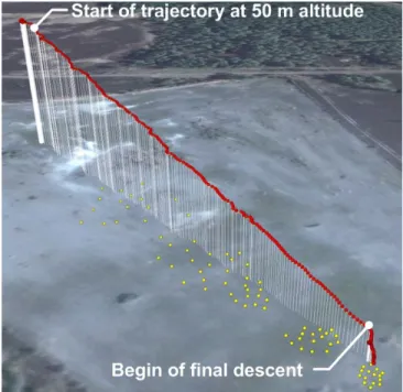
Figure 5. Trajectory of one test flight (red) and crater center positions (yellow) Background: Google Earth
as depicted in Fig. 4. This modular payload concept allows flexible operation of the UAV for different research projects, since the payload can be prepared independently of the he-licopter before the final assembly. This includes calibration and ground testing of the payload.
Flight Test Trajectory
The reference flight test trajectory was defined as a lin-ear path, stretching from north-east to south-west for about 200 m, and from an initial altitude of 50 m down to 10 m. After the slight descent on this path, the helicopter performed an almost vertical descent down to less than 1 m above ground. Figure 5 illustrates this flight profile. This trajectory is a simplified downscaled version of the powered descent with first an almost horizontal flight and a final almost vertical descent.
Sensor Configuration
To perform flight tests with the ATON system, which should be comparable to previously performed open-loop computer simulations and closed-loop simulations using the TRON facility [1], the sensor configuration defined in section 1 had to be emulated in a way that all necessary measurements could be provided to the software modules during the flight test. Furthermore, ground truth data of the flight test had to be generated as well. Therefore, additional sensors for positioning and attitude estimation had to be equipped to the payload.
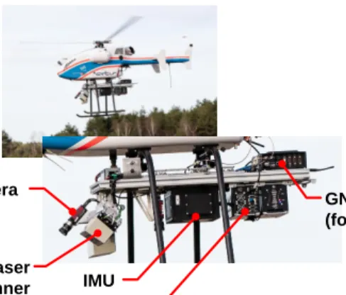
In the following for each sensor from the ATON sensor configuration and for the ground truth generating sensors a description of the sensor actually used in the flight test setup is given. The resulting payload assembly is shown in Fig. 6 and the devices relevant for this paper are marked.
• Inertial Measurement Unit: For acquiring velocity and
angle increments the raw measurements of the tactical-grade IMU integrated in the iMAR iTraceRT-F400-Q-E was used. It features a fiber optic gyroscope and a MEMS accelerometer, both operating at 400Hz. The specifications are given in Table 4.
• 2D Imaging Sensor: Capturing of images was performed by two monocular, monochromatic cameras (AVT Prosilica GT1380). Having been installed in a forward-looking and downward-looking configuration, their resolution was set to 1024 px×1024 px.
• Laser Altimeter: For measuring the altitude of the platform similar to the description of the lander in Fig. 2, a laser scanner (SICK LD-MRS) was used. The laser scanner was configured to have only a small field of view to emulate a laser altimeter.
• Star Tracker: Using an actual star tracker camera intro-duces several challenges, since it requires operation at night. Therefore, arrangements for illumination of the terrain of the flight test area have to be made. Furthermore, operating an UAV at night time introduces legal issues. Consequently, the attitude measurement of the star tracker was simulated online based on the generated ground truth.
• 3D Imaging Sensor: Since there was no flash LIDAR available for the flight test, this sensor has been left out of the flight test. Consequently, also the 3D Matching module from the ATON project had not been part of the flight test.
• Ground Truth Generation: For the ground truth generation two separate sensors were used. For the online ground truth generation the output of the deeply coupled INS/GNSS navi-gation system of the iTraceRT-F400-Q-E was used. The esti-mation navigation solution is based on the tactical-grade IMU (See Table 4) and a dual-antenna, dual-frequency differential GNSS receiver. It has an accuracy of 2cm in position, 0.02m/s in velocity and0.01◦ in attitude estimation. This accuracy meets the requirements, which translate from upper bound of a position accuracy in the order of low one-digit percent of (camera) line-of-sight range with the given flight trajectory from Fig. 5. Additionally, the payload was equipped with the high-grade GNSS receiver NovAtel Propak6. It also fea-tures dual-antenna and dual-frequency GNSS measurements. Furthermore, it uses the German precise satellite positioning service, SAPOS. This service relies on a network of reference stations with precisely known positions to determine correc-tive data for all visible GNSS satellites. With that, offline verification of the online generated ground truth was possible.
GNSS receiver (for ground truth) Camera
Computer IMU
Start of trajectory at 50 m altitude
Begin of final descent
Laser Scanner
Figure 6. Camera, IMU, laser scanner, onboard computing and ground truth hardware installed on
helicopter during flight.
Table 4. IMU (1σ) specifications. Gyroscope Accelerometer
Sensor range ±450deg/s ±5g
Axis misalignment 0.5mrad 0.5mrad Angle/vel. random walk 0.1deg/√h 50µg/√Hz Bias repeatability 0.75deg/h 2mg Scale-factor repeatability 300ppm 1500ppm
Preparation of Flight Test Area
The flight test campaign took place near Braunschweig, Ger-many. The test site features a restricted ground area and a restricted airspace. Therefore, it is suitable for flying large unmanned vehicles like the superARTIS.
For the flight test a gravel ground approximately 300 m ×
300 m wide was chosen. About half of this ground in Fig. 5 was used for the flight operation. The remainder was reserved as safety perimeter for the ground station and test crew area. Obviously, the gravel ground does not feature moon-like structures like impact craters, which are necessary for the crater navigation module to work. Therefore, the ground was prepared using patterns of planar crater targets (Fig. 7). These targets were scattered in a random manner over four sub-fields along the flight trajectory. Altogether, 80 craters with diameters between 5 m and 0.5 m were used. The bigger craters were designated to be located at the part of the trajectory with higher altitude and the smaller craters at parts with lower altitude, ensuring a near-constant coverage of the camera images during the linearly decreasing altitude. After placing the crater planes, they were fixed to the ground (Fig. 7). A picture of the crater scattering can been seen in Fig. 8.
Subsequent to field preparation, a catalog of crater positions was created. The position estimate of the Crater Navigation module is relative to this reference database. For lunar landing or near-asteroid operations the estimated position has to be with respect to the target body. Therefore, in the case of this flight test the crater catalog had to be expressed in an Earth fixed reference frame. To accomplish that task, two steps were performed: First, a tachymeter (Leica TDRA-6000) was used to measure all crater centers and three auxil-iary points in a local frame. Then, using the GNSS position of the three auxiliary points the local crater positions were
Figure 7. Craters after preparation and ready for testing
transformed into the Earth fixed frame. The accuracy of this catalog was approximately of 0.01 to 0.02 m.
4. F
LIGHTT
ESTR
ESULTSThree flight test campaigns have been conducted over the last two years. The first flight test campaign focused on recording flight data from all available sensors. This was followed by a second flight campaign, where the ATON navigation system was tested onboard the unmanned helicopter superARTIS, but without closing the control loop.
The results, which are presented here, originate from the most recent test campaign conducted in March 2017 and have been presented in more detail in [1]. In this campaign, the ATON system was used as the primary navigation system for the autonomous flight of the unmanned helicopter.
Six single flight runs in closed-loop setup were conducted successfully. For each flight, the final altitude above ground was reduced for every test until a final altitude of 0.75 m was achieved. Figures 9 and 10 show the track of the helicopter (ground truth and navigation solution) in the North-East and East-Up planes. The begin of the trajectories is in the point (0,0,0) where the helicopter hovered for a short time before the begin of the descent. The helicopter followed an almost straight path down to an altitude of about 10 m above the landing site. From that point, the helicopter executed a vertical descent down to the final altitude of about 0.75 m. In both plots it can be seen that the true trajectory (blue) and the navigation solution of the ATON system (green) differ only by a small amount.
5. C
ONCLUSIONThis paper provides an overview of the ATON project and presents the applied concept of testing an autonomous terrain-based optical navigation system for lunar landing using an UAV. Several different approaches for testing such navigation systems have been reviewed. The superARTIS unmanned research helicopter of DLR is presented along with the devel-opment steps required to perform the flight tests. The flight test results show the proper function of the optical navigation system developed in the ATON project. Not only has been shown, that the navigation error is low, but also the capability
Figure 8. Helicopter over test field during flight -80 -60 -40 -20 0 East [m] -180 -160 -140 -120 -100 -80 -60 -40 -20 0 North [m] Trajectory in NE plane
Figure 9. Plot of flight trajectory in North-East plane: blue - ground truth, green - ATON navigation solution;
the experiments starts at the point (0,0).
-80 -60 -40 -20 0 East [m] -50 -40 -30 -20 -10 0 Up [m] Trajectory in EU plane
Figure 10. Plot of flight trajectory in East-Up plane: blue - ground truth, green - ATON navigation solution;
the experiments starts at the point (0,0).
to provide the navigation solution in real-time and close the control loop has been demonstrated. This successfully performed flight test shows the maturity of the developed navigation system and also propose closed-loop flight tests using an unmanned helicopter as a solid testing methodology for optical navigation systems for lunar landing.
A
CKNOWLEDGMENTSThe author thanks all colleagues at the German Aerospace Center (DLR) who have contributed to the ATON project and especially to the flight test campaign.
R
EFERENCES[1] S. Theil, N. Ammann, F. Andert, T. Franz, H. Krüger, H. Lehner, M. Lingenauber, D. Lüdtke, B. Maas, C. Pa-proth, and J. Wohlfeil, “ATON - Autonomous Terrain-based Optical Navigation for exploration missions: Re-cent flight test results,” inDeutscher Luft- und Raum-fahrtkongress 2017, September 2017.
[2] D. Geller and D. Christensen, “Linear Covariance Anal-ysis for Powered Lunar Descent and Landing,”Journal of Spacecraft and Rockets, vol. 46, no. 6, 2009. [3] A. Pollini and H. Krüger, “Fosternav: Flash optical
sen-sor for terrain relative navigation,” European Commis-sion’s Directorate-General for Industry and Enterprise, Tech. Rep., 2012.
[4] O. Maibaum, D. Lüdtke, and A. Gerndt, “Tasking Framework: Parallelization of computations in onboard control systems,” in ITG/GI Fachgruppentreffen Be-triebssysteme, Nov. 2013.
[5] T. Franz, D. Lüdtke, O. Maibaum, and A. Gerndt, “Model-based software engineering for an optical navi-gation system for spacecraft,”CEAS Space Journal, Sep 2017.
[6] B. Maass, H. Krüger, and S. Theil, “An edge-free, scale-pose- and illumination-invariant approach to crater de-tection for spacecraft navigation,” in7th International Symposium on Image and Signal Processing and Anal-ysis, Sept. 2011, pp. 603–608.
[7] B. Maass, “Robust approximation of image illumination direction in a segmentation-based crater detection algo-rithm for spacecraft navigation,”CEAS Space Journal, 2016.
[8] H. Kaufmann, M. Lingenauber, T. Bodenmüller, and M. Suppa, “Shadow-based matching for precise and robust absolute self-localization during lunar landings,” in2015 IEEE Aerospace Conference Proceedings, Mar. 2015, pp. 1–13.
[9] J. Shi and C. Tomasi, “Good features to track,” inIEEE Conference on Computer Vision and Pattern Recogni-tion, 1994, pp. 593–600.
[10] B. D. Lucas and T. Kanade, “An iterative image regis-tration technique with an application to stereo vision,” in International Joint Conference on Artificial Intelli-gence, 1981, pp. 674–679.
[11] P. J. Besl and N. D. McKay, “A method for registration of 3-d shapes,”IEEE Trans. Pattern Anal. Mach. Intell., vol. 14, no. 2, pp. 239–256, Feb. 1992.
[12] S. Rusinkiewicz and M. Levoy, “Efficient variants of the ICP algorithm,” inProceedings Third International Conference on 3-D Digital Imaging and Modeling, 2001, pp. 145–152.
[13] N. Ammann and F. Andert, “Visual navigation for au-tonomous, precise and safe landing on celestial bod-ies using unscented kalman filtering,” in 2017 IEEE Aerospace Conference, March 2017, pp. 1–12.
[14] F. Andert, N. Ammann, and B. Maass, “Lidar-aided camera feature tracking and visual SLAM for spacecraft low-orbit navigation and planetary landing,” in CEAS EuroGNC Conference, 2015.
[15] A. E. Johnson and J. F. Montgomery, “Overview of terrain relative navigation approaches for precise lunar landing,” in2008 IEEE Aerospace Conference, March 2008, pp. 1–10.
[16] C. Paproth, E. Schlüßler, P. Scherbaum, and A. Börner, “SENSOR++: Simulation of remote sensing systems from visible to thermal infrared,” in International Archives of the Photogrammetry, Remote Sensing and Spatial Information Sciences, 2012, pp. 257–260. [17] M. Lingenauber, T. Bodenmüller, J. Bartelsen,
B. Maass, H. Krüger, C. Paproth, S. Kuß, and M. Suppa, “Rapid modeling of high resolution moon-like terrain models for testing of optical localization methods,” in 12th Symposium on Advanced Space Technologies in Robotics and Automation. European Space Agency, 2013.
[18] H. Krüger and S. Theil, “TRON - hardware-in-the-loop test facility for lunar descent and landing optical navigation,” in IFAC-ACA 2010 Automatic Control in Aerospace, September 2010.
[19] H. Krüger, S. Theil, M. Sagliano, and S. Hartkopf, “On-ground testing optical navigation systems for explo-ration missions,” in9th International ESA Conference on Guidance, Navigation & Control Systems, Juni 2014. [20] E. D. Skulsky, A. E. Johnson, J. Umland, C. Padgett, B. Martin, S. Weinstein, M. Wallace, A. Steltzner, and S. Thurman, “Rocket sled testing of a prototype terrain-relative navigation system,”24th Annual AAS Guidance and Control Conference, 2001.
[21] D. Rutishauser, C. D. Epp, and E. A. Robertson, “Free-flight terrestrial rocket lander demonstration for nasa’s autonomous landing and hazard avoidance technology (alhat) system,”Proc. of AIAA SPACE, vol. 2012, 2012. [22] G. P. Guizzo, A. Bertoli, A. D. Torre, C. Philippe, M. M. Jurado, G. G. Ori, M. Macdonald, O. Romberg, and S. Debei, “Mars and moon exploration passing through the european precision landing gnc test facility,” in58th International Astronautical Congress 2007, September 2007.
[23] S. Paschall and T. Brady, “Demonstration of a safe and precise planetary landing system on-board a terrestrial rocket,” in 2012 IEEE Aerospace Conference, March 2012, pp. 1–8.
[24] D. P. Scharf, M. W. Regehr, G. M. Vaughan, J. Benito, H. Ansari, M. Aung, A. Johnson, J. Casoliva, S. Mohan, D. Dueri, B. Açikme¸se, D. Masten, and S. Nietfeld, “Adapt demonstrations of onboard large-divert guidance with a VTVL rocket,” in2014 IEEE Aerospace Confer-ence, March 2014, pp. 1–18.
[25] N. Trawny, A. Huertas, M. E. Luna, C. Y. Villalpando, K. Martin, J. M. Carson, A. E. Johnson, C. Restrepo, and V. E. Roback, “Flight testing a real-time hazard detection system for safe lunar landing on the rocket-powered morpheus vehicle,” AIAA Guidance, Naviga-tion, and Control Conference, 2015.
[26] J. Dittrich, A. Bernatz, and F. Thielecke, “Intelligent systems research using a small autonomous rotorcraft testbed,” in2nd AIAA "Unmanned Unlimited" Confer-ence and Workshop & Exhibit. American Institute of Aeronautics and Astronautics, September 2003. [27] F. Adolf, F. Andert, S. Lorenz, L. Goormann, and
J. Dittrich, An Unmanned Helicopter for Autonomous Flights in Urban Terrain. Springer Berlin, 2009, pp. 275–285.
[28] A. Voigt, J. Dauer, A. Krenik, and J. S. Dittrich, “De-tection of forward flight limitations of unmanned
heli-copters,” in American Helicopter Society 72th Annual Forum, Mai 2016, pp. 1–12.
[29] G. Strickert and J. Dittrich, “Realisierung einer Plattform für die Entwicklung unbemannter VTOL Luftfahrzeuge,” in 63. Deutscher Luft- und Raum-fahrtkongress 2014, September 2014.
B
IOGRAPHY[
Nikolaus Ammann received his B.Sc. degree in computer science from the University of Lübeck in 2009. After his study abroad at the Auckland University of Technology in 2010 he graduated from the University of Lübeck in 2012 and received the M.Sc degree. Since then, he works as a research scientist at the German Aerospace Center (DLR). His research activities include sensor fusion and visual navigation for unmanned aerial vehicles (UAVs) and spacecraft.
Stephan Theilreceived the degree of a Diplomingenieur in aerospace engineer-ing from Technical University of Braun-schweig in 1996. After that he has been working for eleven years at the Center of Applied Space Technology and Microgravity (ZARM) at the University of Bremen where he received his PhD degree in 2002. Since ten years he is heading the GNC Systems Department at the Institute of Space Systems of the German Aerospace Center (DLR). He is the project manager of the project Autonomous Terrain-based Optical Navigation (ATON).

![Figure 8. Helicopter over test field during flight -80 -60 -40 -20 0 East [m]-180-160-140-120-100-80-60-40-200North [m] Trajectory in NE plane](https://thumb-us.123doks.com/thumbv2/123dok_us/378940.2541845/7.918.87.840.77.466/figure-helicopter-field-flight-east-north-trajectory-plane.webp)
