Flux Standalone Software Application
Job Scheduler
Workflow Engine
Business Process Management System
Version 6.2, 30 July 2004
End Users Manual
Copyright © 2000-2004 Sims Computing, Inc. All rights reserved.
No part of this document may be copied without the express written permission of Sims Computing, Inc. Flux is a registered trademark of Sims Computing, Inc.
The Flux logo, Sims Computing, and the Sims Computing logo are trademarks of Sims Computing, Inc.
Questions? Our Technical Support department is here to help you. Email [email protected] or telephone +1 (406) 656-7398 for help.
Table of Contents
1 Introduction to Flux ... 5
2 GUI Mechanics... 6
2.1 Dockable Frames ... 7
2.2 Manipulating Dockable Frames... 8
2.2.1 Opened, Closed, Visible, Invisible Dockable Frames ... 8
2.2.2 Dockable Frame Attributes... 9
2.2.3 Dockable Frames Summary... 9
2.3 Undo and Redo ... 10
3 Typical Job Scheduler Activities ... 10
3.2 Defining a Job... 12
3.2.1 Cleaning Up a Job... 15
3.2.2 Setting Action Properties... 16
3.3 Starting a Flux Job Scheduler Server... 19
3.4 Exporting that Job to your Job Scheduling Server ... 20
3.5 Watching that Job Run... 21
3.6 Shutting Down your Job Scheduler Server... 23
4 Command Line Interface ... 25
4.1 Java Class Path ... 25
4.2 Embedding the License Key File in flux.jar... 25
4.3 Main Flux Class... 26
4.4 Putting It All Together... 26
4.5 Displaying Basic Help Information ... 27
4.6 Help Command... 27
4.7 GUI Command... 27
4.8 Additional Options for the Server and Client Commands... 28
4.8.1 Properties Configuration File ... 28
4.8.2 XML Configuration File... 28 4.8.3 Host... 28 4.8.4 Registry Port ... 29 4.8.5 Server Name ... 29 4.9 Server Command ... 29 4.9.1 Security ... 29
4.10.1 Security ... 32
5 Engine Properties Configuration File ... 32
5.1 Database Tables ... 33
5.2 Database Properties ... 33
5.2.1 Initializing Database Connections ... 34
5.3 Additional Database Information ... 35
5.4 Clustering and Failover... 35
6 Runtime Configuration File... 35
6.1 Tree of Configuration Properties ... 35
6.2 Concurrency Throttle Properties... 36
6.2.1 Concurrency Level... 36
6.2.2 More Complex Concurrency Throttles... 37
6.2.3 Heavyweight and Lightweight Jobs... 37
6.2.4 Job Pinning ... 37
6.2.5 Running Some Jobs When Other Jobs Are Not Running... 38
6.2.6 Enforcing Concurrency Throttles Cluster-Wide... 39
6.3 Job Priorities ... 39
6.3.1 Job Priorities Example... 40
6.4 Default Flow Chart Error Handler... 40
7 Scheduling and Time Expressions... 41
7.1 Time Expression Examples ... 41
8 Business Process Management ... 42
8.1 Modeling a Business Process... 42
8.3 Login to the Business Process Engine ... 43
8.4 Export the Business Process to the Business Process Engine ... 44
8.5 Find Business Processes ... 44
8.6 Confirm Business Process Triggers... 44
8.7 Claim Business Process Triggers... 45
8.8 Participants, Users, and Roles ... 45
8.9 Business Process Reminders... 45
9 Exception Handling ... 46
9.1 Controlling When the Database Exception Action Runs ... 47
9.2 Exception Condition Syntax ... 48
10 Secure FTP Configuration ... 48
10.1 Secure FTP Host Authentication ... 49
11 Design Best Practices ... 50
12 Troubleshooting... 50
13 Performance Best Practices ... 52
14 Database Migration from Flux 5 to Flux 6 ... 54
15 Trigger and Action Properties Documentation... 54
16 Examples... 54
17 Web Services Installation and Configuration ... 54
17.1 Exclusively for the Flux Web Service for Java Clients... 55
17.2 Exclusively for the Flux Web Service for XML Clients ... 56
17.3 For both Flux Web Services ... 56
1
Introduction to Flux
Flux is both a standalone software application and a software component for performing enterprise job scheduling. Job scheduling is a traditional function that executes different tasks at the right time or when the right events occur. The Flux job scheduler software performs this functionality in Java, J2EE, XML, and Web Services environments.
Flux models jobs using a traditional flow chart, also known as a workflow. Like any flow chart, a job therefore consists of triggers, actions, and flows. These triggers, actions, and flows can be combined to create arbitrarily complex flow charts.
A trigger waits for an event to occur. Traditionally, such events are based on time. For example, a trigger can fire at 9 AM and 4 PM, Monday through Friday, except on company holidays. Other triggers include waiting for files to arrive on FTP servers and responding to activities that occur in other software systems in the enterprise, such as financial settlement engines, messaging systems, and email servers.
Technically, a trigger is a kind of action (described below), so when this documentation generically refers to actions, it can be referring to triggers as well.
An action performs some function such as updating a database, calling into a J2EE application, or communicating with different software systems. These functions are arbitrary. Flux itself comes with a suite of actions for performing a variety of tasks.
A flow connects a trigger or action to another trigger or action. For example, after a trigger has fired, a flow may guide execution into an appropriate action. Flows can be conditional or unconditional. For example, when a file trigger fires when a file arrives on an FTP server, execution may unconditionally flow into a database action. On the other hand, when a different email trigger fires, execution may branch to different actions depending on who the sender of the email is.
Throughout this document, the terms flow chart and job are used interchangeably. Furthermore, in general, actions and triggers are generally referred to as flow chart nodes or just nodes.
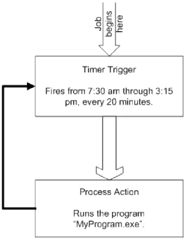
The following example illustrates how Flux defines a job using a common flow chart. below represents a job or flow chart. This job fires from 7:45 am through 3:15 pm, every 20 minutes. When the job fires, a program called MyProgram.exe is executed.
Figure 1: Sample Flow Chart or Job
To understand how this sample flow chart works, think of the flow chart at the starting gate labeled “Job begins here”. As this job begins to run, the job flows into the rectangle labeled “Timer Trigger”. This rectangle, called a Timer Trigger, fires on a schedule. Once the Timer Trigger is entered, the job waits until the right time occurs. In other words, the job waits for the clock to reach 7:30 am, 7:50 am, 8:10 am, etc.
Once the right time is reached, the job flows into the next rectangle in the flow chart, called Process Action. The Process Action executes a program. In this case, the program is called MyProgram.exe. After MyProgram.exe finishes executing, the job follows the black arrow back up to the Timer Trigger. Once again, the Timer Trigger waits for the clock to reach the right time. Then the job repeats as before.
2
GUI Mechanics
2.1
Dockable Frames
The Flux GUI consists of an outer main GUI frame plus multiple dockable frames inside the main GUI frame. Each dockable frame contains important information about your jobs and your job scheduler engines.
By using dockable frames, the Flux GUI can display all kinds of job scheduler information, from different sources, in a single GUI frame. For example, you can monitor jobs from two different job scheduler engines at the same time simply by opening two different dockable frames, each one displaying job information from different job scheduler engines.
Mechanically speaking, a dockable frame is a kind of independent window that can attach itself to the left side of the main GUI frame, on the inside of the outer frame. Each dockable frame can “slide” to the left to close or “slide” to the right to open. This sliding behavior is referred as Auto Hide behavior, which is described in greater detail in Section 2.2.2.
As an example, see . That figure shows the outer main GUI frame and three dockable frames inside: Figure 3
• In this figure, the “Project View” dockable frame is at the top and shows the flow charts and time expressions in your project. In this figure, the Project View dockable frame is open and located at the top of the GUI.
The “Project View” dockable frame contains information about your project workspace, which is located on your local desktop or laptop computer, not your server. The Project View is a tree of job definitions (flow charts) and time expressions (schedules). The items in your Project View tree are stored locally as files on your computer.
You create your jobs and time expressions in your local Project View tree. When you are ready, you can export these jobs to live job scheduler engines for execution. Moreover, you can email your job definitions to other users, and they can view them graphically in the Flux GUI.
It is very important to remember that your Project View is merely a local storage area for flow chart and time expressions definitions. The Project View does not contain any live, running jobs. It merely stores job definitions for convenient editing and viewing. Live, running jobs are always stored in a job scheduler engine.
• In this figure, the “Flow Chart Overview” dockable frame is at the bottom and shows a “flyover” view of the currently opened flow chart. In this figure, the Flow Chart Overview dockable frame is open and positioned at the bottom. Since there are no opened flow charts, the contents flyover are blank.
However, if a flow chart was open, the flyover dockable frame shows the entire contents from a “10,000 foot high” point of view. Use the flyover to move over large flow charts and zoom in on different sections of those flow charts.
• In this figure, the “Job Scheduler Engines” dockable frame is on the left side and is closed. Click this dockable frame so that it opens. Once open, use the icons at the top of the dockable frame to register job scheduler engines. You can display the jobs from registered job scheduler engines and export jobs from your project workspace to registered job scheduler engines.
2.2
Manipulating Dockable Frames
There are a variety of ways to manipulate dockable frames. Each dockable frame is a smaller window that is either:
• Open, in which case your data and information are displayed in the dockable frame.
• Closed, in which case the dockable frame is closed and represented by a “tab” on the left side of the outer main GUI frame.
One caveat: when the Flux GUI is run for the first time, the Project View and Flow Chart Overview dockable frames are open but there is no corresponding “tab” on the left side of the main GUI frame. Once you close these two dockable frames for the first time, their tabs will appear.
• Invisible, in which case the dockable frame is closed and there is no tab.
2.2.1
Opened, Closed, Visible, Invisible Dockable Frames
Each dockable frame can be opened, closed, made invisible, and made visible again. Note that each dockable frame is represented by a tab on the left side of the screen, except in one case. If a dockable frame is open and that frame’s “push pin” icon is pressed in (displayed in an up-and-down orientation), then the tab is not displayed.
• Open a dockable frame, briefly. To open a dockable frame briefly, move your mouse over the appropriate tab on the left side of the main GUI frame, but do not click the tab. The
dockable frame will slide open. Once you move your mouse off the tab or the dockable frame, it closes again. If there is no tab displayed for a dockable frame, you cannot briefly open it. • Open a dockable frame and keep it open (until it loses focus). To open a dockable frame
and keep it open, click the appropriate tab on the left side of the main GUI frame. If there is no tab, navigate to the View menu, display the View menu, and set the checkbox next to the dockable frame that you want to open.
To close this dockable frame, simply click elsewhere in the Flux GUI so that the dockable frame loses focus, at which time it will close.
• Open a dockable frame and keep it open indefinitely. To open a dockable frame and keep it open indefinitely, open the dockable frame as described above. Next, click the “push pin” icon on the dockable frame so that it is “pushed in” or in an up-and-down orientation.
To close this dockable frame, remove the “push pin” by clicking the push pin icon so that it is in a left-to-right orientation, at which time your dockable frame will close.
• Close a dockable frame. To close a dockable frame, click elsewhere in the Flux GUI so that the dockable frame loses focus. Once the dockable frame loses focus, it will close.
One caveat: if the “push pin” icon on your dockable frame is “pushed in”, that is, in an up-and-down orientation, then the only way to close such a dockable frame is to remove the push pin. To remove the push pin, click the “push pin” icon so that it is in a left-to-right orientation.
• Make a dockable frame invisible. To make a dockable frame disappear, click the “close” icon, in the shape of an “X”, on the dockable frame. At that time, the dockable frame will be made invisible.
Alternately, to make a dockable frame invisible, navigate to the View menu, display the View menu, and clear the checkbox next to the dockable frame that you want to make invisible. At that time, the dockable frame will disappear.
• Make a dockable frame visible. To make an invisible dockable frame visible again, navigate to the View menu, display the View menu, and set the checkbox next to the dockable frame that you want to make visible again.
2.2.2
Dockable Frame Attributes
Each dockable frame has a few attributes that can be enabled or disabled. Turning on different combinations of attributes fine-tunes the behavior of the dockable frames.
• Auto Hide. The Auto Hide attribute indicates that a dockable frame can be opened briefly, as described above in Section 2.2.1. Auto Hide dockable frames slide to the side of the main GUI frame in order to create more room on the screen for other dockable frames.
• Hide. The Hide attribute indicates that the dockable frame is not visible. To make it reappear, you must navigate to the View menu and select the checkbox next to the dockable frame that you want to make visible.
• Floating. The Floating attribute means that the dockable frame is detached from the main GUI frame. A Floating dockable frame can be dragged to a new location on the main GUI frame and be re-docked. Alternately, to automatically re-dock a Floating dockable frame, clear the Floating check box on the dockable frame’s title bar. That dockable frame will automatically re-dock to the main GUI frame.
• Dockable. If a dockable frame is not dockable, it implies that it is Floating. On the other hand, if a dockable frame is dockable, it can be made to re-dock to the main GUI frame, as described above under Floating.
In case your dockable frames become a confusing mess, you can reset them. Simply exit the Flux GUI, navigate to your project directory, and delete the file called myproject.fdl, where myproject.fpr is the name of your Flux project file. This myproject.fdl file contains your dockable frames layout. By deleting that file, your dockable frames will reset to the standard layout.
2.2.3
Dockable Frames Summary
Now you have the basic knowledge to manipulate dockable frames, which contain your job scheduling data. By using dockable frames, you can display different sets of job scheduling information at the same time. You can display two different jobs at the same time side-by-side, then focus on one job by closing the other job’s dockable frame.
By using different dockable frame data layouts, you can display all the job scheduling information that you need to see in a single view.
2.3
Undo and Redo
When you are drawing flow charts using the drawing canvas (described below in Section 3.2), you can “undo” and “redo” your drawing moves. For example, when you “lay down” a trigger or action in your flow chart or draw a flow between two actions, you can “undo” your work by navigating to the Edit menu and selecting Undo.
Similarly, to “redo” your work that has just been “undone”, navigate to the Edit menu and select Redo. Note that the only GUI actions that are applicable to Undo and Redo are:
• Laying down a new trigger or action on the drawing canvas. • Deleting an existing trigger or action from the drawing canvas. • Creating a flow between two actions.
• Deleting an existing flow between two actions.
Take careful note that you cannot undo or redo changes to the layout in your drawing canvas. For example, if you move an action from the left side of your drawing canvas to the right side, you cannot undo or redo that movement. In fact, if you click Undo or Redo, the last creation or deletion activity described above will be undone or redone, so use Undo and Redo with caution until you are
comfortable with its behavior.
3
Typical Job Scheduler Activities
This section describes typical interactions that you will have with the Flux job scheduler. Once you are familiar with these typical job scheduler activities, you can use this knowledge to create other kinds of jobs that meet your application and operational needs.
You will be walked through the typical steps of:
1. Starting the Flux GUI. You use the Flux GUI to define your jobs and monitor them once they have begun running.
2. Defining a job. You define a job by drawing a flow chart in the Flux GUI.
3. Starting a Flux job scheduler server. The server is responsible for actually running your jobs. You need to create the server before your job will run.
4. Exporting that job to your job scheduler server. Once a job has been defined and your server has been started, you export your job to your server. Once exported, your job can run. 5. Watching that job run. Once your job has been exported and starts running on your server,
you monitor it through the Flux GUI and observe it running in your computer system.
1. Install the Java software package, version 1.4 or greater, available from “www.java.com”. 2. Install the Flux download bundle, available from
“www.simscomputing.com/products/flux/download.jsp”. The Flux download bundle will be installed in a directory (also known as a “folder”) on your hard drive. This directory is called your “Flux installation directory”.
3.1
Starting the Flux GUI
Once your Java and Flux software are installed, you need to run the Flux GUI. The Flux GUI is both a job designer and a job monitor. To run the Flux GUI, you can:
• Click on the “Flux GUI” program button installed on your desktop.
• Run the “fluxgui.bat” Windows batch file or the “fluxgui” Unix shell script from your Flux installation directory.
You will know that the Flux GUI is running when it displays a Flux splash screen and eventually displays the main Flux screen. The Flux splash screen is shown below in Figure 2.
Figure 2: Splash Screen
Figure 3: Main Screen
If you see the main Flux screen, similar to the screen shown above, you have successfully started the Flux GUI.
3.2
Defining a Job
Now that your Flux GUI is up, you need to define a new job. From the “File” menu, select “New”. In the “New” dialog box that appears, select “New Flow Chart” and click OK.
Remember that Flux models jobs using a flow chart or workflow, so when you see the term “flow chart”, you can substitute the word “job” or “workflow” and have the correct meaning.
In the “New Flow Chart” dialog, enter a name for your job. In this example, the job will be called “myjob”. Then click OK.
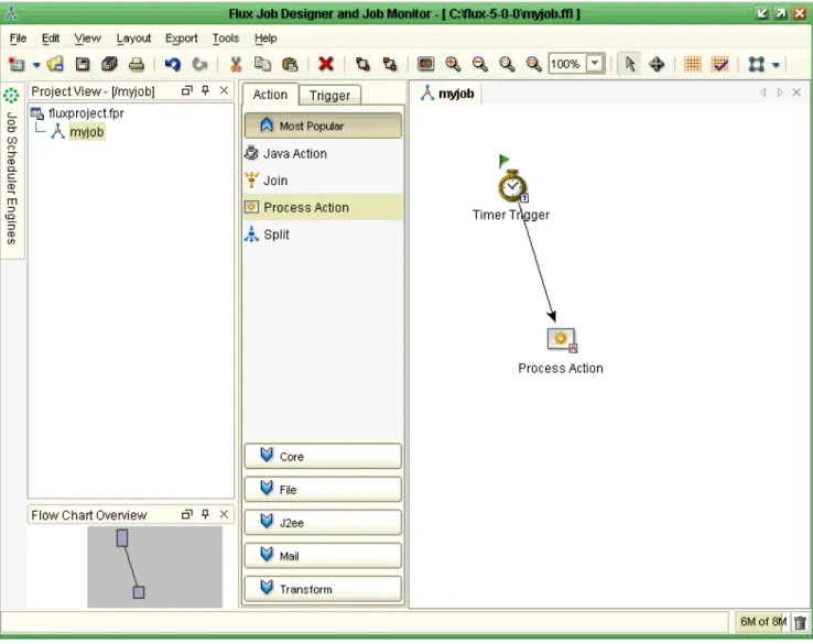
In your Project View, notice that “myjob” has been created in the project tree. Also look for the drawing canvas that was created, whose title is “myjob”. On the left side of the drawing canvas, there are two tabs, “Action” and “Trigger”, which display the actions and triggers available to your job. Use the screen shot below in Figure 4 as a guide.
Figure 4: Defining the Job "myjob"
Now you are ready to begin defining your job. Click on the Trigger tab on the left side of the drawing canvas. While holding down your left mouse button, select and drag the Timer Trigger icon from the tabbed area onto the drawing canvas.
This Timer Trigger controls when, and how often, your job fires.
Next, we need to drag-and-drop a Process Action onto the drawing canvas. Click on the Action tab and then the Core button at the bottom of the tab. Then, while holding down your left mouse button, select and drag the Process Action onto the drawing canvas.
Figure 5: Laying Out the Job "myjob"
Next, you must draw a flow from the Timer Trigger to the Process Action. To draw the flow, click in the white background area of the drawing canvas to clear any selections. There should not be any gray “selection” squares positioned on any actions in the drawing canvas. Then, while pressing and holding down your left mouse button, click on the Timer Trigger and drag the arrowhead to the Process Action. You will see an arrow being drawn from your Timer Trigger to your Process Action. Finally, release your mouse button.
Figure 6: Drawing Canvas for "myjob"
This flow, represented by an arrow on the drawing canvas, indicates that when the Timer Trigger fires on its schedule, the job flows down to the Process Action in order to execute your program.
Next, you need to draw a second arrow from the Process Action back to the Timer Trigger. To draw the second arrow, click in the white background area of the drawing canvas to clear any selections, click and hold the Process Action icon, draw the arrow off to the side of the Process Action, release the left mouse button, and finish drawing the arrow into the Timer Trigger.
Congratulations, you have created a flow chart (job), complete with a Timer Trigger to define the firing schedule, a Process Action to define the program that is executed on that schedule, and the flows between these two flow chart nodes.
3.2.1
Cleaning Up a Job
Just in case your flow chart drawing skills are not perfect, the Flux GUI provides a way to reposition the elements of your flow chart in a pleasing manner.
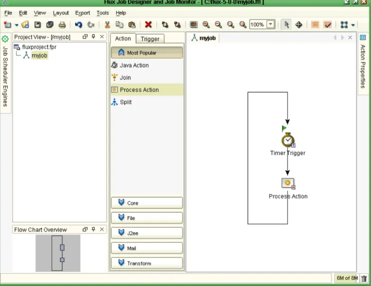
To redraw your flow chart, navigate to the Layout menu, select Hierarchic Layout, and click OK. Notice how your flow chart is redrawn and tidied up. The redrawn drawing canvas for “myjob” is shown below in Figure 7.
Figure 7: Redrawn Flow Chart
Just for the fun of it, use the Layout menu to explore the other layouts to see how they redraw and re-layout your flow chart. Remember that the particular re-layout of a flow chart does not affect the behavior of a flow chart, only its appearance.
3.2.2
Setting Action Properties
Now that your flow chart has been created, including your Timer Trigger and Process Action flow chart nodes and your flows, you need to configure your Timer Trigger and Process Action.
• Timer Trigger. Your Timer Trigger needs to be configured to fire on a set schedule. To keep things simple for this example, you will define your schedule to fire every minute, at the top of the minute, except the top of the hour.
To define your top-of-every-minute schedule, click on the Timer Trigger flow chart node to select it. Notice that an Action Properties panel appears on the right, as shown below in
.
Figure 8
Figure 8: Action Properties
These properties provide you with a way to configure your Timer Trigger so that it fires according to the schedule that you define.
Find the Time Expression property. Click on the “…” symbol so that the Time Expression Editor appears.
Click on the “+” button to add a new time expression. Then click on the Guided tab to define your schedule. In Flux, a schedule is referred to as a time expression. Flux time expressions are
extremely powerful, succinct expressions of schedules. You will find that Flux time expressions can express just about any timing or scheduling constraint that you will want. Click in the Name text field, and give your time expression a name. Then click in the Description text field, and describe your time expression. Then click the Next button.
In the next pane, you are given a choice of creating a Cron-style time expression or a Relative time expression. If it is not already selected, select the Cron-style radio button. Then click Next.
In the next pane, you will create a regular Cron expression. If it is not already selected, select the Regular Cron radio button. Then click Next.
Create a time expression that fires at the top of every minute, except the top of the hour. To meet this requirement, you need to set a 0 in the milliseconds column of the Cron-style time expression. Imagine a clock on the wall that has not only hour and minute hands, but second and millisecond hands. On your imaginary clock, the millisecond hand speeds around the face of the clock once per second, passing through 1000 millisecond ticks each time. The second hand is a bit slower, taking a full minute to circumnavigate the face of the clock.
In a Cron-style time expression, you specify the values that the hands of the clock must be on in order for your job to fire. We require the millisecond hand to be on 0, the second hand to be on 0, and the minute hand to be on any number between 1 and 59, inclusive. This specification means that your new schedule fires only at the top of the second, the top of the minute, every minute except the 0th minute, which is the top of the hour.
To meet this need, update your time expression using the time expression editor. You need to clear the checkbox next to these three columns before you can type in values in the Column Value text field.
Put a 0 in the millisecond column of the time expression editor, if it is not already there. Similarly, put a 0 in the seconds column, if it is not already there. Finally, make sure the Minutes column checkbox is cleared, click in the Minutes text field, then click the Start button. Now click the “Run within a range” radio button. Select “From 1” at the top, “To 59” on the second line. Next, click the “+” button. Finally, click the Finish button.
In the end, your Cron-style time expression should look like the following string.
0 0 1-59 * * * * * * * *
To verify that your time expression is correct, click the Test button. The Test Time Expression dialog appears. Now press the Test button. You will see five test firing dates appear in the display. Verify that they are scheduled to fire at the top of every minute, but not the top of the hour.
Once you have verified your time expression and your schedule, click OK. If your time expression does not provide the schedule that you intended, go back, make sure your time expression was edited correctly, and try again.
Now that you have created a time expression (schedule) that fires at the top of every minute, click the Next button to go to the “Cron ‘OR’ Constructs” pane. Do nothing here. Now click the “Finish” button.
Finally, make sure your new time expression is highlighted and click OK. You will notice that your Timer Trigger’s Time Expression property has changed to “0 0 1-59 * * * * * * * *”. Finally, edit the Count property in the Timer Trigger and set it to 3. The Count property indicates that the Timer Trigger will fire at most 3 times before stopping.
Congratulations, you have successfully configured the Timer Trigger with a schedule that fires at the top of every minute.
• Process Action. Your Process Action needs to be configured to run a program. To configure your Process Action, click on the Process Action icon on the drawing canvas to see the Process Action’s configuration properties in the Action Properties panel. Click on the Command property and type in notepad.exe or any other program name in your computer system.
Congratulations, you have successfully configured the Process Action with a command to run the notepad.exe program.
Finally, save your work by clicking on the File menu, followed by the Save All menu item. Your job definition is then saved to your hard drive.
Congratulations, you have successfully defined a job. Next, you will run your job.
3.3
Starting a Flux Job Scheduler Server
Before you can run your job, you must create a job scheduler server. Flux provides a command line interface for creating Flux servers from command prompts, shells, and scripts. The Flux command line interface is fully documented in Section 4, but the following description shows you how to use part of the Flux command line interface to start a job scheduler server.
First, you need to open a command prompt or shell to start the Flux job scheduler server. Navigate to your Flux installation directory and open a command prompt or shell located in your Flux installation directory. Then run the “fluxserverstart.bat” Windows batch file or the “fluxserverstart” Unix shell script from your Flux installation directory.
This command creates and starts a Flux server. Note that without the trailing “start” option in the above batch and script files, a Flux server would be created but not started. Such a stopped server is fully functional, except that it does not fire jobs.
Figure 9: Starting Flux Job Scheduler Server
If it interests you to see the Java command line details, look at the “fluxserverstart.bat” or
“fluxserverstart” files. As you will see, the command line details to create and start a job scheduler server are fairly simple.
3.4
Exporting that Job to your Job Scheduling Server
Now that you have defined a job and started a Flux job scheduler server, you are ready to export your job to the server and cause it to begin running. To export your job, you first need to inform the Flux GUI of the available Flux job scheduler servers.
To do that, click on the dockable frame entitled, “Job Scheduler Engines”, located on the upper left side of the Flux GUI in a downward orientation.
Next, click on the green “+” button to add a new engine and use the wizard to locate your Flux job scheduler server that was started in the previous step.
The fast way to accomplish this task is to click on the Advanced tab, then click OK. You will see that an engine has been added to your Job Scheduler Engines dockable frame with a green icon. The green icon indicates that the engine is up and is available. In this case, the engine is located on the localhost at RMI Registry port 1099 using the server name “Flux”.
Use the screen shot below in Figure 10 as a guide. The Job Scheduler Engines dockable frame is in the upper left corner of the screen shot.
Figure 10: Job Scheduler Engines
Next, close the Job Scheduler Engines dockable frame by clicking the “X” button in the upper right corner of the frame. Return to the “Project View” dockable frame. Right-click “myjob” and click on “Export to Remote Flux Job Scheduler Engine”. In the dialog that appears, you will see your job scheduler engine located in the bottom center of the dialog. Click it, and then click OK.
You should see a confirmation message indicating that you have successfully exported your job to your Flux job scheduler server.
3.5
Watching that Job Run
Now that your job has been exported successfully, it will start firing according to the schedule set in your Timer Trigger. In this running example, the Notepad program will appear at the top of the next minute (unless it is the top of the hour), wait for you to close it, then appear again on the same schedule.
Note that if you wait longer than one minute to close Notepad, the next Notepad will appear immediately after you close the first one, because the Timer Trigger is attempting to maintain a set
schedule of running Notepad every minute. There are a variety of features in Flux that you can use to react to this kind of late job, but that discussion is beyond the scope of this example.
Now that your job is firing on its top-of-the-minute schedule, you can monitor that job through the Flux GUI. Find and open the Job Scheduler Engines dockable frame in the upper left corner. If you cannot find it, you can display it from the View menu by ensuring that the Job Scheduler Engines menu item is checked.
Once the Job Scheduler Engines dockable frame is open, highlight your engine by clicking on it and then click the Job Monitor icon at the top of the Job Scheduler Engines dockable frame, second from the right.
When you click on this icon when an engine is highlighted, a job monitor for that engine appears in the Flux GUI.
The screen shot below in shows the mouse hovering over the Monitor Jobs icon at the top of the Job Scheduler Engines dockable frame.
After you click the Reload Jobs button, a job monitor is displayed for that particular job scheduler engine, as shown below in Figure 12.
Figure 12: Job Monitor
The job monitor displays the jobs in a job scheduler engine and lets you display information about each running job. The job monitor represents a snapshot of a job scheduler engine. Because jobs continue to run in the background in the engine, you may want to update the job monitor snapshot from time to time.
To update the job monitor snapshot, simply return to the Job Scheduler Engines dockable frame, click on your engine to select it, and then click the Reload Jobs icon to refresh the job monitor.
Once the job is displayed in the job monitor, you can display the current flow chart action’s properties by double-clicking underneath the Current Action column. You can also display the full
two-dimensional flow chart by double-clicking underneath the Name column.
Finally, once a row in the job monitor is selected, you can expedite, resume, pause, interrupt, remove that job or copy it back into your local workspace for further viewing and editing.
3.6
Shutting Down your Job Scheduler Server
You have now performed a complete “round trip” in the Flux job scheduler system. You have defined a new job, created a job scheduler server, and exported the job to the server, monitored the job. Now you are ready to shut down the server.
To shut down your job scheduler server, you first need to open a command prompt or shell to start the Flux job scheduler server.
Navigate to your Flux installation directory and open a command prompt or shell located in your Flux installation directory. Then run the “fluxservershutdown.bat” Windows batch file or the
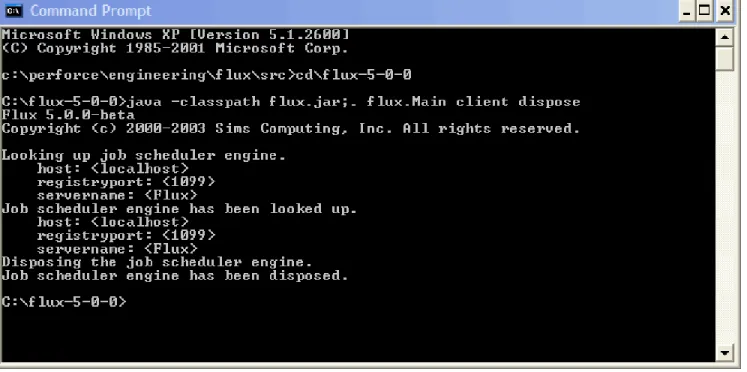
This command shuts down your Flux server. A screen shot of the client command used to shut down a Flux server is shown below in Figure 13.
Figure 13: Shut Down Server from Client
If it interests you to see the Java command line details, look at the “fluxservershutdown.bat” or “fluxservershutdown” files. As you will see, the command line details to create and start a job scheduler server are fairly simple.
4
Command Line Interface
Flux provides a command line interface for running the Flux GUI (Job Designer and Job Monitor), creating job scheduler engines, starting those engines, stopping the engines, and shutting down the engines.
4.1
Java Class Path
To get started, you need to learn about the Java class path. The class path is a list of directories and jar
files that contain the files necessary to run the Flux software. Flux itself is distributed as a jar file, called “flux.jar”. You will also need a license key file to run Flux. The name of this file is “fluxkey-X-Y.txt”, where “X” is the major version number of the Flux software, and “Y” is the minor version number. For example, the name of the license key file for Flux 5.0 “fluxkey-5-0.txt”.
When you run the Flux software, you typically include “flux.jar” on your Java class path in addition to the special directory called “.”, which means the current directory.
Each jar file and directory name is separated by a path separator character. On Windows, this character is a semi-colon: “;”. On Unix, it is a colon: “:”.
For example, a typical Java class path on Windows is:
.;flux.jar
You can add additional jar files and directories onto your Java class path. Just make sure a path separator character is inserted between the file and directory names.
4.2
Embedding the License Key File in flux.jar
In order to make it easier to keep your Flux software and license key file together, users frequently embed the Flux license key file into the flux.jar file itself. The following command line program shows how to embed a Flux 5.0 license key file into a flux.jar file.
jar –uvf flux.jar fluxkey-5-0.txt
After performing this step, you can be sure that your File license key file is always located with your Flux software.
Note that the “jar” command is available only if you downloaded the Java SDK. The Java Runtime Environment does not contain the “jar” command.
However, even if you do not have the “jar” command available to you, you can use any “Zip” file tool, such as WinZip, to accomplish the same purpose. For example, to use WinZip to embed the Flux license key file in the flux.jar file, simply use WinZip to open your flux.jar file. Because jar files are also valid zip files, this step works fine.
Next, add the Flux license key file, “fluxkey-5-0.txt” in the above example, to the “root” or uppermost-level of the flux.jar Zip archive. Finally, exit the WinZip program.
At this point, you will have updated the flux.jar file in the same way that the above “jar” command would, but instead of using the “jar” command, you used a Zip file tool.
4.3
Main Flux Class
When you run any Java software, execution begins from a “main” class. In Flux, this main class is called “flux.Main”.
4.4
Putting It All Together
To run the Flux software from the command line, you run a Java Virtual Machine, combined with the Flux software located in the file flux.jar, the Flux license key file, and the Main Flux class. The following command line for Windows shows how to display basic help information for Flux.
java –classpath .;flux.jar flux.Main
The output is shown below.
Flux 5.0.0
Copyright (c) 2000-2003 Sims Computing, Inc. All rights reserved. Released on 29 August 2003.
Sims Computing
www.simscomputing.com [email protected]
For a list of command line options, use the "help" command. Example: java -jar flux.jar help
If you inserted the Flux license key file into your flux.jar, as described in Section 4.2, you can simplify the command line as shown below, using the Windows path separator character.
java –jar flux.jar
The output, shown below, is identical to the output shown above.
Flux 5.0.0
Sims Computing
www.simscomputing.com [email protected]
For a list of command line options, use the "help" command. Example: java -jar flux.jar help
Of course, if you need to add additional jar files and directories to the Java class path, you need to use the “-classpath” option, described above, instead of the “-jar” option. Be sure to add your extra jar files and directories to the list of jar files and directories entered after the “-classpath” command line option.
4.5
Displaying Basic Help Information
The examples in the rest of this section will use the “-classpath” option as well as the Windows path separator character.
To display basic help information, run the following command.
java –classpath .;flux.jar flux.Main help
This help command displays all available commands:
• client: Runs a command on a pre-existing Flux job scheduler instance. • gui: Launches the Flux GUI.
• help: Displays help messages for each command.
• server: Creates and optionally starts a Flux job scheduler instance.
4.6
Help Command
The help command provides basic and detailed help information on each of the available commands. For example, to show the details of all the command line options for the “server” command, run the following command.
java –classpath .;flux.jar flux.Main help server
4.7
GUI Command
To run the Flux GUI, also known as the Job Designer and Job Monitor, run the following command.
4.8
Additional Options for the Server and Client Commands
The “server” and “client” commands, described below in Sections 4.9 and 4.9.1, take additional options that the other commands do not take. Before discussing the server and client commands, these additional options must be reviewed first.
4.8.1
Properties Configuration File
A Flux properties configuration file specifies a variety of configuration options for configuring the runtime behavior of a Flux job scheduler engine. It can also be used to specify the necessary properties in order to lookup an existing job scheduler server.
The file format is in the form of a “properties” file, which has a understand and simple-to-edit format. See Section 5 for details on how to create a properties configuration file to configure an engine.
In addition, see the Javadoc documentation for the flux.Configuration interface for complete details on available configuration properties. For an example properties configuration file, see the “config” example in the Flux download bundle under the “examples” directory.
To view this Javadoc documentation, navigate to the “doc/javadoc” directory in your Flux package and open the file “index.html” with your Web browser. Then navigate to the flux.Configuration interface.
4.8.2
XML Configuration File
A Flux properties configuration file specifies a variety of configuration options for configuring the runtime behavior of a Flux job scheduler engine. It can also be used to specify the necessary properties in order to lookup an existing job scheduler server.
The file format is in the form of an XML file, which can be edited using a variety of XML editors available from a number of sources.
See the Javadoc documentation for the flux.Configuration interface for complete details on available configuration properties. For an example XML configuration file, see the “xml_config” example in the Flux download bundle under the “examples” directory.
To view this Javadoc documentation, navigate to the “doc/javadoc” directory in your Flux package and open the file “index.html” with your Web browser. Then navigate to the flux.Configuration interface.
4.8.3
Host
Used only by the “client” command and not the “server” command, the host option specifies the name or IP address of the computer where the job scheduler server is running. The client command uses the host option to know which computer to contact in order to find a job scheduler server.
The host option defaults to “localhost”, but you can change it to any host name or IP address that is reachable across the network.
4.8.4
Registry Port
When a Flux job scheduler server is created, it is created as an RMI server. An RMI server is a server that uses Java technology to communicate across networks. By creating Flux job scheduler engines as RMI servers, you can communicate with the servers you create from other computers. Furthermore, the Flux GUI can communicate with your servers as well. In fact, the Flux GUI does not need to run on the same computer as your job scheduler server.
Whenever an RMI server is created, it registers itself with the RMI Registry. The RMI registry is simply a lookup table that associates names to servers. The RMI registry requires an RMI port. An RMI port is simply a TCP/IP port that must be available for use on your computer.
The default registry port is 1099, but you can change it to any available TCP/IP port, such as 5812.
4.8.5
Server Name
Whenever an RMI server is created, it registers itself with the RMI registry using a particular name. You can look up different job scheduler servers by looking up different server names in the RMI registry.
The default server name is “Flux”, but you can change it to any other name. In fact, if you start two job scheduler servers on the same computer, the second server must be provided a unique server name. Otherwise, the first server’s entry in the RMI registry will be overwritten, consequently making the first server inaccessible to clients and GUIs.
4.9
Server Command
To create a job scheduler server, run the following command.
java –classpath .;flux.jar flux.Main server
By default, a job scheduler engine is created, but it is not started. A job scheduler engine that is not started can be contacted, queried, and update, but jobs do not run or fire.
To create a job scheduler server and start it at the same time, run the following command.
java –classpath .;flux.jar flux.Main server start
4.9.1
Security
For a working example of creating and accessing a secure job schedule engine, see the security example in the “examples/end_users/security” directory underneath your Flux installation directory.
A job scheduler server can be created with security enabled on it. To enable security, you must use a configuration file when creating the job scheduler server. At a minimum, the configuration must set the configuration property SECURITY_ENABLED to true.
For example, to create a job scheduler server with security enabled, run the following command:
java –classpath .;flux.jar flux.Main server –cp fluxconfig.properties
At a minimum, the file “fluxconfig.properties” must contain following line:
SECURITY_ENABLED=true
When security is enabled, a “security policy file” is used. This policy file is used to assign permissions to the Flux software as well as individual Flux users and roles.
By default, the name of the security policy file is “fluxjaas.policy”. You can specify a different file name by changing the SECURITY_POLICY_FILE configuration property.
Additionally, when security is enabled, a “security configuration file” is used. This configuration file is used to configure how usernames and passwords are obtained.
By default, the name of the security configuration file is “fluxjaas.config”. You can specify a different file name by changing the SECURITY_CONFIGURATION_FILE configuration property. Also by default, the name of the entry that is consulted is called “security-configuration”. You can specify a different name by changing the SECURITY_CONFIGURATION_FILE_ENTRY configuration property. Flux uses the standard Java Authentication and Authorization Service (JAAS) to implement security. The security policy file and security configuration file mentioned above conform to a syntax that JAAS requires. To be sure, the JAAS syntax is not easy at first, but if you work with it, over time, it will become easier. Note that when using security and JAAS, Flux requires a Java Runtime Environment (JRE) version 1.4 or greater. Due to JAAS changes that occurred from JRE 1.3 and JRE 1.4, Flux security will not work with JRE 1.3.
The sample “fluxjaas.config” file that is shipped with Flux refers to a JAAS “login module” called “flux.security.SimpleLoginModule”. Other JAAS login modules can be substituted here, but you can use the included login module, which stores users, roles, and passwords in a file called
“fluxusers.properties”.
A working security policy file, a working security configuration file, and a working user file is included with the Flux distribution. Look for the following files in the Flux installation directory.
• fluxjaas.policy: This policy file describes two roles: administrator and user. In Flux, the
administrator role can perform every function. The user role can perform every function except:
o dispose a job scheduler engine
o use the Publisher Administrator
o use the Messaging Administrator
Besides the two roles, you can assign permissions to users. You can assign users permissions to read and write to jobs located in different branches of the tree of jobs. You can also assign user the right to use the Message Administrator or Publisher Administrator.
This fluxjaas.policy file conforms to JAAS syntax.
• fluxjaas.config: This configuration file specifies a JAAS login module. Flux ships with a default login module, which lets you assign users and roles in a file called
“fluxusers.properties”, described below.
If you want to use your own JAAS login module to retrieve usernames and passwords from a different location, enter the name in the “fluxjaas.config” file. For example, you might have a JAAS login module that retrieves usernames and passwords from the operating system, a database, or an LDAP server.
This fluxjaas.config file conforms to JAAS syntax.
• fluxusers.properties: The format of the “fluxusers.properties” file is simple:
o user=password
The username is on the left of the equal sign, and that user’s password is on the right-hand side.
For example, the following entry specifies a user named “mary” and a Mary’s password is “lamb”.
mary=lamb
o user.role=role_name
The username is on the far left. Next, the required string “.role” is placed immediately to the right of the username, just to the left of the equal sign. Finally, the actual role name is on the right-hand side of the equal sign.
For example, the following entry specifies that the user “mary” is in the “user” role.
mary.role=user
4.10
Client Command
To query or update an existing job scheduler server, use the “client” command. The client command can be used to:
• Start a job scheduler server to allow jobs to begin firing. • Stop a job scheduler server so that jobs stop firing.
• Query a job scheduler server to see if jobs are eligible to fire. • Dispose a job scheduler server.
4.10.1
Security
For a working example of creating and accessing a secure job schedule engine, see the security example in the “examples/end_users/security” directory underneath your Flux installation directory. Since a job scheduler server can be created with security enabled on it, as described in Section 4.9.1, the client command may have to present username and password information in order to be able to login to the job scheduler server and run commands on it.
If the client accesses a job scheduler server with security enabled on it (a secured engine), then the client command will prompt you for a username and password. Alternately, you can specify the username and password directly on the client command line.
5
Engine Properties Configuration File
Unless you are using a job scheduler engine with all its default configuration properties, you will need a properties configuration file to fine-tune the configuration of your job scheduler engines.
Each configuration parameter is documented in the Javadoc documentation for the flux.Configuration
interface. See this Javadoc documentation for complete details on available configuration properties. Also, for an example properties configuration file, see the “config” example in the Flux download bundle under the “examples” directory.
To view this Javadoc documentation, navigate to the “doc/javadoc” directory in your Flux package and open the file “index.html” with your Web browser. Then navigate to the flux.Configuration interface. Notice that there are many fields documented in the flux.Configuration interface. To set any of these configuration properties in a properties configuration file, follow these steps.
1. Create a properties configuration file by using a text editor to create a file called “fluxconfig.properties”.
2. For each configuration property that you want to set, find that name of that property, its value, and place a line in the fluxconfig.properties file like so:
RMI_SERVER=true REGISTRY_PORT=1099 SERVER_NAME=Flux
3. Refer to this file when creating a job scheduler engine, as described in Section 4.8.1.
The three properties shown above should always be used when creating a Flux job scheduler engine from the command line interface. These three properties ensure that your job scheduler engine is created as an RMI server, which is needed for communications between the Flux GUI and the job scheduler engine.
5.1
Database Tables
By default, Flux uses the HSQL in-memory database for storing jobs. When you shutdown your Flux engine, your job data is lost. However, this HSQL in-memory database is very convenient for getting started with Flux without having to configure Flux to use a real database.
To store your job data in a real database so that your job information is available after the Flux engine restarts, you need to create a set of Flux tables. The database table creation statements (DDL) are available in the “doc” directory under your Flux installation directory. Find the file that contains the name of your database with the file extension “.sql”. This file is called the DDL file. For example, if you use Oracle, look for the file called “oracle.sql”. Then run that script in your database to create the necessary Flux database tables.
Open the file, and examine its contents. You will see several statements that create tables. If you need to modify any database types, use caution, but you can edit the .sql file directly.
You will also see several statements that create indexes. These indexes increase the Flux engine’s performance and reduce the chances of database deadlock.
If you need to change the names of any database tables or columns, see the next section for instructions on how to change the names of tables and columns that Flux uses.
5.2
Database Properties
The following configuration properties can be used to connect a job scheduler engine to your database. The following properties provide a typical scenario for connecting a job scheduler engine to an Oracle database.
By using a database, such as Oracle, the job scheduler can store jobs in your relational database. This way, your jobs will still be available after you shut down and restart your job scheduler engine. (By default, Flux uses an HSQL in-memory database for storing jobs; these jobs are lost when the engine is shut down.) TABLE_CREATION_MODE=NEVER TABLE_PREFIX=FLUX_ DRIVER=oracle.jdbc.driver.OracleDriver URL=jdbc:oracle:thin:@127.0.0.1:1521:orcl JDBC_USERNAME=system JDBC_PASSWORD=manager
You may need to adjust these configuration properties to suit your particular database installation. Also, be sure to include any necessary jar files for your database’s JDBC driver on the job scheduler server’s command line.
Note that when using the HSQL in-memory database for storing jobs and database tables are automatically created, the default column sizes are as follows.
SQL Type Default Column Size
BLOB 10000 DECIMAL 9, 2
VARBINARY 10000 VARCHAR 128
Furthermore, when using the HSQL in-memory database for storing jobs and database tables are automatically created, the BLOB SQL type is mapped to VARBINARY, and the CLOB SQL type is mapped to LONGVARCHAR.
Other optional database properties of interest are listed below.
Database Property Default
Value Examples
DATABASE_TYPE DEFAULT ORACLE, DB2, SQL_SERVER, MYSQL
DATABASE_PROPERTIES.TABLE.NAME Default table
names are found in the DDL file.
FLOW_CHART.NAME=FLOWCHARTS Renames the table “FLOW_CHART” to “FLOWCHARTS”.
DATABASE_PROPERITES.TABLE.COLUMN.NAME Default
column names are found in the DDL file.
VARIABLE.TYPE.NAME=THE_TYPE Renames the “TYPE” column in the “VARIABLE” table to “THE_TYPE”.
DATABASE_TYPE: If your database is MySQL, you must set this property to MYSQL. For other databases, you do not need to set this property, but doing so increases the performance of Flux with your database.
DATABASE_PROPERTIES.TABLE.NAME: Renames the table TABLE to a different name. Do not include any table prefix.
DATABASE_PROPERTIES.TABLE.COLUMN.NAME: Renames the column COLUMN in the table
TABLE to a different name. Do not include any table prefix.
5.2.1
Initializing Database Connections
When the engine acquires its database connections directly from a database server, you have the option of executing custom SQL initialization statements on the JDBC connections as they are created. Some database servers and their JDBC drivers, such as Informix, require special initialization in order to work with Flux.
To initialize a JDBC connection with custom SQL, set the following property in your database properties file.
If more than one initialization SQL statement is needed, you can create additional properties, as shown below.
CONNECTION_INIT.2=this SQL initialization statement runs second CONNECTION_INIT.3=this SQL initialization statement runs third
As many additional properties may be set as required.
5.3
Additional Database Information
The Databases and Persistence section of the Flux Software Developers Manual contains additional information on configuring Flux with different databases.
5.4
Clustering and Failover
Flux can be clustered to provide improved reliability and greater job throughput. Creating a cluster is easy. Simply instantiate multiple job scheduler engines, and point each job scheduler engine at the same set of database tables.
Once this step is done, your job scheduler engines cooperate to fire and fail over jobs.
Note that clustering and failover does not work with HSQL’s in-memory database, which is the default Flux database.
6
Runtime Configuration File
Two components are used to configure a job scheduling and workflow engine:
• Engine Configuration Properties File: This file accepts configuration properties that are set when a Flux engine is created. These configuration options cannot be changed after the engine is created.
• Runtime Configuration File: This file contains a tree of configuration options that can be changed after the engine has been created.
To configuration the runtime configuration file, you must put the following line into your engine properties configuration file:
RUNTIME_CONFIGURATION_FILE=fluxruntimeconfig.properties
The name of your runtime configuration file, “fluxruntimeconfig.properties”, can, of course, be changed to a different name.
To set your runtime configuration properties, put appropriate lines in the “fluxruntimeconfig.properties” file as explained below.
The runtime configuration consists of a tree of nodes, set up in the usual tree structure. Each node contains a set of configuration properties as well as links to its parent and its children. Each configuration property consists of a key and a value.
Although the runtime configuration tree can contain any kind of property, it includes pre-defined properties as described below.
Flow chart names are hierarchical. They form a tree of jobs. For example, the two jobs “/lightweights/job 1” and “/heavyweights/job 2” form a tree with two branches off the root, “/lightweights” and “/heavyweights”.
You can annotate this tree of jobs using properties in the runtime configuration. For example, to set a concurrency throttle (explained in detail below) for heavyweight jobs, set an appropriate concurrency throttle in the “/heavyweights” branch of the runtime configuration tree. To set a default flow chart error handler (explained in detail below) for lightweight jobs, set an appropriate error handler in the “/lightweights” branch of the runtime configuration tree.
In summary, the tree of configuration properties mirrors the tree of jobs. A job’s behavior can be further configured based on the branches in the runtime configuration tree that correspond to that job’s fully qualified name.
6.2
Concurrency Throttle Properties
Flux’s concurrency throttles allow you to restrict the number of jobs that can execute at the same time. Without these restrictions, jobs could quickly overwhelm your computer with running jobs.
You can use concurrency throttles to indicate that no more than N jobs in the entire system are allowed to execute at the same time. You can also specify, for example, that only two heavyweight jobs can run at the same time but up to 15 lightweight jobs can run simultaneously. This concurrency throttle
ensures that heavyweight jobs do not bog down your system but that most lightweight jobs have the opportunity to run.
You can take concurrency throttles even farther. You can specify that one class of jobs will run only if another class of jobs is not running.
Finally, using a technique called job pinning, you can specify that certain jobs will run only on certain computers. Job pinning is a good way to restrict Unix jobs to running on Unix machines and Windows jobs to running on Windows machines within your cluster.
6.2.1
Concurrency Level
The simplest kind of concurrency throttle is the concurrency level. The concurrency level is a positive number that indicates that maximum number of jobs that may fire simultaneously in a job scheduler engine.
CONCURRENCY_LEVEL=5
The above example configuration property restricts the maximum number of jobs that run at the same time to five.
In general, the rule of thumb is that for CPU-bound jobs, you should not allow more jobs to fire simultaneously than twice the number of CPUs in your computer. But of course, this rule is just a general guideline. You will undoubtedly fine-tune it depending on the capabilities of your computer systems, your networks, and the kinds of jobs you are running.
6.2.2
More Complex Concurrency Throttles
To configure more complex concurrency throttles, as explained below, you need to specify them in your runtime configuration file.
6.2.3
Heavyweight and Lightweight Jobs
For example, to specify that the /heavyweight/ branch of the job scheduler’s tree of jobs is allowed to run at most three jobs at a time, put the following line into your fluxruntimeconfig.properties file.
/heavyweight/CONCURRENCY_THROTTLE = 3
Similarly, to specify that up to 15 jobs in the /lightweight/ branch of the job tree can run simultaneously, append the following line to your fluxruntimeconfig.properties file.
/lightweight/CONCURRENCY_THROTTLE = 15
Together, these two configuration lines form a complete concurrency throttle:
/heavyweight/CONCURRENCY_THROTTLE = 3 /lightweight/CONCURRENCY_THROTTLE = 15
Finally, you can exercise greater control over these heavyweight and lightweight jobs. You can specify that under no circumstances can more than 16 jobs run at a time:
/heavyweight/CONCURRENCY_THROTTLE = 3 /lightweight/CONCURRENCY_THROTTLE = 15 /CONCURRENCY_THROTTLE = 16
Although the /lightweight/ branch of the job tree allows up to 15 jobs to run at a time, if all three heavyweight jobs are currently running, there is room only for 13 lightweight jobs to run, since the sum of 3 and 13 is 16, the maximum number of jobs overall that are allowed to fire simultaneously.
6.2.4
Job Pinning
To require that Unix machines avoid running Windows jobs, and vice-versa, use a concurrency throttle file like the one shown below on your Unix machines.
/unix/CONCURRENCY_THROTTLE = 5 /windows/CONCURRENCY_THROTTLE = 0 /java/CONCURRENCY_THROTTLE = 3
In the above concurrency throttle, up to 5 Unix jobs and 3 Java jobs can run at the same time, but no Windows jobs may run.
Use the opposite concurrency throttle file on your Windows machines.
/unix/CONCURRENCY_THROTTLE = 0 /windows/CONCURRENCY_THROTTLE = 5 /java/CONCURRENCY_THROTTLE = 3
6.2.5
Running Some Jobs When Other Jobs Are Not Running
Suppose you have some jobs that create data (“producer” jobs) and other jobs that process data (“consumer” jobs). Further suppose that due to the particulars of your system architecture, your producer jobs must not run at the same time as your consumer jobs.
Concurrency throttles can enforce this restriction.
/producers/CONCURRENCY_THROTTLE = /consumers/ = 0 /consumers/CONCURRENCY_THROTTLE = /producers/ = 0 /CONCURRENCY_THROTTLE = 5
This concurrency throttle stipulates that a producer job can run only if the number of currently firing consumer jobs is zero. Similarly, a consumer job can run only if the number of currently firing producer jobs is zero. But under no circumstances can more than 5 jobs run in the system overall. The concurrency throttle expression “/consumers/ = 0” can be extended by using the “and” operator, denoted by “&”. For example, to specify that up to one reporting job can run when producer jobs are running, use the following concurrency throttle expression.
/consumers/ = 0 & /reports/ <= 1
In general, a concurrency throttle expression that consists of only a number is shorthand “the number of concurrency executing jobs in the current branch in the tree of jobs is less than or equal to that number”.
For example, consider the following line in a concurrency throttle file.
/lightweight/CONCURRENCY_THROTTLE = 15
The line above is equivalent to the line below.
6.2.6
Enforcing Concurrency Throttles Cluster-Wide
All of the above examples configure the behavior of a single job scheduler engine instance. Therefore, these concurrency throttle limits control the behavior of a single job scheduler instance, which is usually the desired behavior. If a single job scheduler engine can run two heavyweight jobs, then two job scheduler engines ought to be able to run four heavyweight jobs.
However, this assumption is not always accurate. Sometimes jobs are so resource-intensive that the number of such jobs that execute simultaneously across the entire cluster must be regulated. For instance, suppose your resource-intensive jobs contact an external software system to generate reports. If too many report jobs contacted your reporting engine at the same time, it could be overwhelmed. A cluster-wide concurrency throttle prevents such overloads from occurring.
To set a cluster-wide concurrency throttle, use the same syntax as the above examples, except refer to the property CONCURRENCY_THROTTLE_CLUSTER_WIDE instead of
CONCURRENCY_THROTTLE.
In that case, each job scheduler engine will monitor other job scheduler engines to make sure these cluster-wide concurrency throttles are enforced at each job scheduler engine. Note, however, that each job scheduler engine must be configured to cooperate in the same way. If one job scheduler engine is configured differently, it will not respect the cluster-wide concurrency throttle limits observed by the other job scheduler engines.
6.3
Job Priorities
Every job is assigned a priority. Higher priority jobs generally run before lower priority jobs. Job priorities make it possible to specify that important or time-critical jobs need to run before other, less important, jobs. Job priorities allow you to specify that if two jobs could otherwise both execute at the same time but concurrency throttles will allow only one of those two jobs to run, the job with the higher priority runs first.
Concurrency throttles take precedence over job priorities. A concurrency throttle tends to prevent jobs from running, whether they are high priority jobs or low priority jobs. However, once a concurrency throttle allows a job to execute, priorities come into play as described above.
The highest priority is 1. Lower priorities have values greater than 1, such as 10, 25, 500, etc. If two different jobs have different priorities, the job with the priority closer to 1 runs first. If two different jobs have the same priority, then the job with the oldest timestamp runs first. Each running job contains a timestamp that indicates the next time the job requires attention from the Flux engine. It is possible that higher priority jobs will run so frequently as to prevent lower priority jobs from running at an acceptable rate. This behavior is called starvation, that is, lower priority jobs can be starved or prevented from running as frequently as you would like. By default, Flux permits starvation, because it often does not cause any serious problems, and it is sometimes desirable.
If starvation impacts you adversely, you can enable the Flux configuration property
JOB_FAIRNESS_TIME_WINDOW. This property contains a time expression that indicates how
frequently starved jobs should have their priorities increased by 1 (the effective priority). (To increase a job's effective priority, its numerical value is decremented by 1.) Eventually, such jobs will reach an effective priority of 1 and be eligible for execution before all other jobs. After firing, such jobs revert to their original priorities and are again eligible to have their priorities increased if they starve. This anti-starvation behavior is called fairness.
Note that whenever a trigger fires internally, even if it does not fire out of the trigger and force execution of the job to continue to the next action, that flow chart’s effective priority is reset to its original priority.
Job priorities are stored in an engine’s runtime configuration. Each branch in the runtime configuration tree can contain a PRIORITY property, which specifies the priorities of all jobs in that branch of the tree. If a PRIORITY property is not explicitly set, the engine searches higher branches in the runtime configuration until it finds a PRIORITY property. If no explicit PRIORITY property is found, even at the root of the tree, then the job defaults to a priority of 10.
Changes made to PRIORITY properties in the runtime configuration tree are propagated to running jobs in the engine.
6.3.1
Job Priorities Example
Suppose you want to configure your jobs in the following manner.
1. Jobs at or underneath the /WIRE_TRANSFER branch in the tree of jobs run at priority 1. 2. Jobs at or underneath the /FILE_TRANSFER branch run at priority 5.
3. All other jobs run at priority 15.
To create this runtime configuration, put the following lines into your runtime configuration file.
/WIRE_TRANSFER/PRIORITY=1 /FILE_TRANSFER/PRIORITY=5 /PRIORITY=15
6.4
Default Flow Chart Error Handler
Sometimes jobs fail. They can fail for a variety of reasons. If an individual job trigger or action fails, it throws an exception. If an explicit error flow leading away from the failed action, a default error handler is u