Advancing Iris Biometric Technology
Mohammed A. M. Abdullah
Newcastle University
Newcastle-upon-Tyne, UK
A thesis submitted for the degree of
Doctor of Philosophy
TO my parents, my beloved wife,Maab
AND
Declaration
I, Mohammed Abdulmuttaleb M. Abdullah, hereby declare that this thesis is my own work and effort and that it has not been submitted anywhere for any award.
Signature:
Student: Mohammed Abdulmuttaleb M. Abdullah
Abstract
The iris biometric is a well-established technology which is already in use in several nation-scale applications and it is still an active research area with sev-eral unsolved problems. This work focuses on three key problems in iris bio-metrics namely: segmentation, protection and cross-matching. Three novel methods in each of these areas are proposed and analyzed thoroughly. In terms of iris segmentation, a novel iris segmentation method is designed based on a fusion of an expanding and a shrinking active contour by inte-grating a new pressure force within the Gradient Vector Flow (GVF) active contour model. In addition, a new method for closed eye detection is pro-posed. The experimental results on the CASIA V4, MMU2, UBIRIS V1 and UBIRIS V2 databases show that the proposed method achieves state-of-the-art results in terms of segmentation accuracy and recognition performance while being computationally more efficient. In this context, improvements by 60.5%, 42% and 48.7% are achieved in segmentation accuracy for the CASIA V4, MMU2 and UBIRIS V1 databases, respectively. For the UBIRIS V2 database, a superior time reduction is reported (85.7%) while maintain-ing a similar accuracy. Similarly, considerable time improvements by 63.8%, 56.6% and 29.3% are achieved for the CASIA V4, MMU2 and UBIRIS V1 databases, respectively.
With respect to iris biometric protection, a novel security architecture is de-signed to protect the integrity of iris images and templates using watermark-ing and Visual Cryptography (VC). Firstly, for protectwatermark-ing the iris image, text which carries personal information is embedded in the middle band frequency region of the iris image using a novel watermarking algorithm that randomly interchanges multiple middle band pairs of the Discrete Cosine Transform (DCT). Secondly, for iris template protection, VC is utilized to protect the
iris template. In addition, the integrity of the stored template in the biometric smart card is guaranteed by using the hash signatures. The proposed method has a minimal effect on the iris recognition performance of only 3.6% and 4.9% for the CASIA V4 and UBIRIS V1 databases, respectively. In addition, the VC scheme is designed to be readily applied to protect any biometric bi-nary template without any degradation to the recognition performance with a complexity of onlyO(N).
As for cross-spectral matching, a framework is designed which is capable of matching iris images in different lighting conditions. The first method is de-signed to work with registered iris images where the key idea is to synthesize the corresponding Near Infra-Red (NIR) images from the Visible Light (VL) images using an Artificial Neural Network (ANN) while the second method is capable of working with unregistered iris images based on integrating the Gabor filter with different photometric normalization models and descriptors along with decision level fusion to achieve the cross-spectral matching. A significant improvement by 79.3% in cross-spectral matching performance is attained for the UTIRIS database. As for the PolyU database, the proposed verification method achieved an improvement by 83.9% in terms of NIR vs Red channel matching which confirms the efficiency of the proposed method. In summary, the most important open issues in exploiting the iris biomet-ric are presented and novel methods to address these problems are proposed. Hence, this work will help to establish a more robust iris recognition system due to the development of an accurate segmentation method working for iris images taken under both the VL and NIR. In addition, the proposed protec-tion scheme paves the way for a secure iris images and templates storage. Moreover, the proposed framework for cross-spectral matching will help to employ the iris biometric in several security applications such as surveillance at-a-distance and automated watch-list identification.
Statement of Originality
This is to certify that to the best of my knowledge, the content of this thesis is my own work. This thesis has not been submitted for any degree or other purposes.
This thesis has three contribution chapters and the publications arising from these chapters are listed below.
1. Chapter 4: Iris Segmentation with the Active Contour Model
• M. A. M. Abdullah, S. S. Dlay, W. L. Woo and J. A. Chambers “Robust
iris segmentation method based on a new active contour force with a noncir-cular normalization,” IEEE Transactions on System, Man and Cybernetics: Systems, vol. In press, pp. 1-14, May, 2016.
• M. A. M. Abdullah, S. S. Dlay and W. L. Woo “Fast and accurate method for
complete iris segmentation with active contour and morphology,”2014 IEEE International Conference on Imaging Systems and Techniques (IST2014), pp.123-128, 2014.
• M. A. M. Abdullah, S. S. Dlay and W. L. Woo “Fast and accurate pupil
isola-tion based on morphology and active contour,”The 4th International confer-ence on Signal, Image Processing and Applications, pp. 418-420, 2014.
2. Chapter 5: Iris Biometrics Protection with Watermarking and Visual
Cryp-tography
• M. A. M. Abdullah, S. S. Dlay, W. L. Woo and J. A. Chambers “A framework
for iris biometric protection: A marriage between watermarking and visual cryptography,”IEEE Access, vol. 4, pp. 10180-10193, November, 2016.
• M. A. M. Abdullah, S. S. Dlay and W. L. Woo “Securing iris images with
a robust watermarking algorithm based on discrete cosine transform,” 10th International Conference on Computer Vision Theory and Applications (VIS-APP 2015), pp. 108-114, 2015.
3. Chapter 6: Cross-spectral Iris Matching
• M. A. M. Abdullah, R. R Al-Nima, S. S. Dlay, W. L. Woo and J. A. Chambers
“Cross-spectral iris matching for surveillance applications,” Surveillance in Action, Book section, Springer, In press, 2017.
• M. A. M. Abdullah, S. S. Dlay, W. L. Woo and J. A. Chambers “A novel
framework for cross-spectral iris matching,”IPSJ Transactions on Computer Vision and Applications, vol. 8, pp. 1-9, November, 2016. (Invited)
• M. A. M. Abdullah, S. S. Dlay, W. L. Woo and J. A. Chambers “Iris
biomet-ric: Is the near-infrared spectrum always the best?,”3rd Asian Conference on Pattern Recognition (ACPR2015), pp. 816-819, 2015.
4. Other contributions
• S.A.M.Al-Sumaidaee,M. A. M. Abdullah, R.R.O.Al-Nimaa, S.S. Dlay and J. A. Chambers “Multi-gradient features and elongated quinary pattern encoding for image-based facial expression recognition,” Pattern Recognition, vol. 71, pp. 249-263, November, 2017.
• R.R.O.Al-Nima, M. A. M. Abdullah, M.T.S. Al-Kaltakchi, S.S. Dlay, W. L. Woo and J. A. Chambers “Finger texture biometric verification exploiting Multi-scale Sobel Angles Local Binary Pattern features and score-based fu-sion,” Digital Signal Processing, vol. 70, pp. 178-189, November, 2017.
Acknowledgments
I am using this opportunity to express my sincere gratitude to many kind people around me who supported me throughout my PhD study. It would not have been possible to write this thesis without their help and support, to whom I would like to give particular mention here.
First and foremost I wish to thank my first supervisors, Prof. Jonathon Chambers and Prof. Satnam Dlay, for their inspirational guidance and constructive criticism which paved the way during my study. I received unlimited help and support, from them I learned how to think positively and how to be a successful researcher. I would also like to express my great appreciation to my third supervisor, Dr. Wai Woo, for his invaluable advices. I am sincerely grateful to all of my supervisors for being supportive and helpful since the days I began working on my project.
I would like to show my deepest appreciation to the Ministry of Higher Education and Scientific Research in Iraq for the award of a fully-sponsored scholarship that provided the necessary financial support during my PhD study. I also would like to acknowledge the academic and technical support of the Iraqi cultural attache in London and the University of Mosul and Ninevah University for providing me with study leave to gain the degree of PhD from Newcastle University. I also thank the School of Electrical and Electronic Engineering for their assistance and support since my first day in the school, especially the kind Postgraduate Research Coordinator, Gillian Webber and the lovely Receptionist, Deborah Alexander.
I owe a very important debt to my parents, brother and sisters who have given me their endless love and support throughout. Without their encouragement, this thesis would not have been written.
Last but not least, my heartfelt appreciation goes to my wife, Maab, and my sons, Zakariya & Zain for their support and great patience at all times. From them I stole great moments and special days for the sake of study. They offered me all these sacrifices without showing any grievance. My lovely family has been a constant source of love, motivation and energy, for which my mere expression of thanks is really inadequate.
Contents
Abstracts . . . iii
Statement of Originality . . . v
Acknowledgments . . . vii
List of Acronym . . . xiii
List of Figure xviii List of Tables xx 1 Introduction 1 1.1 Introduction . . . 2
1.2 Biometric Traits . . . 2
1.3 Common Biometric Traits . . . 3
1.3.1 Fingerprint Recognition . . . 3 1.3.2 Face Recognition . . . 5 1.3.3 Hand Geometry . . . 5 1.3.4 Iris Recognition . . . 5 1.3.5 Periocular Recognition . . . 6 1.3.6 Sclera Recognition . . . 6 1.3.7 Speaker Recognition . . . 6 1.3.8 Signature Recognition . . . 7 1.3.9 Gait Recognition . . . 7 1.4 Modes of Functioning . . . 7
1.5 Aims of the Work . . . 8
1.7 Thesis Outline . . . 10
2 Background of Iris Recognition 13 2.1 Background of Iris Recognition . . . 14
2.1.1 History . . . 14
2.1.2 Anatomy and Properties of the Human Iris . . . 15
2.2 Iris Recognition System . . . 17
2.3 Image Acquisition . . . 17
2.4 Iris Segmentation . . . 19
2.4.1 Hough Transform . . . 19
2.4.2 Integro-Differential Operator (IDO) . . . 20
2.4.3 Active Contour . . . 20
2.4.4 Other segmentation methods . . . 21
2.5 Normalization . . . 21
2.5.1 Rubber Sheet Model . . . 21
2.5.2 Virtual Circles . . . 23
2.6 Feature Extraction . . . 23
2.6.1 Gabor Filter . . . 24
2.6.2 Log-Gabor Filters . . . 25
2.7 Matching . . . 25
2.7.1 Weighted Euclidean Distance . . . 26
2.7.2 Hamming Distance . . . 26
2.8 Summary . . . 27
3 Performance Evaluation and Databases 28 3.1 Biometric System Evaluation . . . 29
3.2 Matching Performance . . . 29
3.3 Performance Graph . . . 31
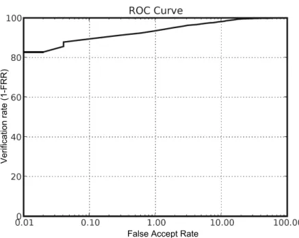
3.3.1 ROC Curves . . . 31
3.3.2 DET Curves . . . 31
3.4 Biometrics Fusion . . . 33
3.5.1 Public deployments . . . 34
3.5.1.1 The United Arab Emirates Border Crossing . . . 34
3.5.1.2 The Unique Identification Authority of India . . . 35
3.5.1.3 Other Deployments . . . 35
3.6 Public Iris Databases . . . 35
3.6.1 CASIA Database . . . 36
3.6.2 MMU Database . . . 37
3.6.3 UBIRIS Database . . . 37
3.6.4 Other Iris Databases . . . 39
3.7 Summary . . . 41
4 Iris Segmentation with the Active Contour Model 42 4.1 Introduction . . . 43
4.2 Related Work . . . 44
4.3 Active Contour Model . . . 46
4.3.1 Active Contour Model . . . 47
4.3.2 Gradient Vector Flow Active Contour . . . 49
4.4 Proposed Active Contour Model . . . 51
4.5 Proposed Iris Segmentation Method . . . 53
4.5.1 Pupil Segmentation . . . 53
4.5.1.1 Segmentation of the Pupil Captured under NIR Light . 54 4.5.1.2 Segmentation of the Pupil Captured under Visible Light 56 4.5.2 Iris Segmentation with the Proposed Active Contour . . . 60
4.5.2.1 Eyelashes Removal . . . 60
4.5.2.2 Active Contour Initialization . . . 61
4.5.2.3 Utilizing the Eyelid Position . . . 61
4.5.2.4 Eyelids Removal . . . 62
4.5.3 Noncircular Normalization . . . 62
4.5.4 Feature Extraction and Matching . . . 64
4.6 Results and Discussions . . . 65
4.6.2 Performance Comparison . . . 70
4.6.3 Computation Time . . . 74
4.7 Summary . . . 75
5 Iris Biometrics Protection with Watermarking and Visual Cryptography 77 5.1 Introduction . . . 78
5.2 Related Work . . . 79
5.3 Watermarking Algorithms and Visual Cryptography . . . 83
5.3.1 Watermarking Algorithms . . . 83
5.3.2 Watermarking Requirements from a Biometric Prospective . . . . 84
5.3.3 Visual Cryptography . . . 84
5.4 The Proposed Method . . . 85
5.4.1 Stage one: iris images watermarking . . . 85
5.4.1.1 Embedding algorithm . . . 88
5.4.1.2 Strength of watermark . . . 91
5.4.1.3 Detection algorithm . . . 91
5.4.2 Stage Two: Visual Cryptography . . . 92
5.4.2.1 Enrolment module . . . 92
5.4.2.2 Authentication module . . . 92
5.5 Experimental Design and Results . . . 94
5.5.1 Stage one: watermarking . . . 94
5.5.1.1 Watermark Perceptibility . . . 95
5.5.1.2 Effect on Matching Performance . . . 95
5.5.1.3 Performance against compression and noise . . . 96
5.5.1.4 Performance against image manipulations and attacks . 96 5.5.1.5 Comparison with other watermarking methods . . . 98
5.5.2 Stage two: visual cryptography . . . 98
5.5.2.1 Adjacent pixels correlation . . . 100
5.5.2.2 Pixel distribution test . . . 101
5.5.2.3 Share to template matching . . . 101
5.5.3 Computation Time . . . 102
5.5.4 Comparisons with state-of-the-art methods . . . 103
5.5.5 Applicability and Limitations . . . 106
5.6 Summary . . . 107
6 Cross-spectral Iris Matching 108 6.1 Introduction . . . 109
6.2 Related Work . . . 110
6.3 Iris Pigmentation . . . 112
6.4 Proposed Cross-Spectral Iris Matching Framework . . . 113
6.4.1 Matching of Registered Images . . . 114
6.4.2 Matching of Unregistered Images . . . 115
6.4.2.1 Difference of Gaussian (DoG) . . . 116
6.4.3 Binarized Statistical Image Features (BSIF) . . . 116
6.4.4 Multi-Scale Weberfaces (MSW) . . . 117
6.4.5 Proposed Scheme . . . 117
6.5 Results and Discussion . . . 118
6.5.1 Pre-processing and Feature Extraction . . . 118
6.5.2 Light-Eyed vs. Dark-Eyed . . . 121
6.5.3 NIR vs. VL Performance . . . 121
6.5.4 Cross-spectral Experiments . . . 122
6.5.4.1 Cross-spectral Matching of Registered Images . . . 124
6.5.4.2 Cross-spectral Matching of Unregistered Images . . . . 125
6.5.5 Multi-spectral Iris Recognition . . . 128
6.5.6 Comparisons with Related Work . . . 129
6.5.7 Processing Time . . . 130
6.6 Summary . . . 131
7 Conclusions and Future Work 132
List of Acronym
ANN Artificial Neural Networks
AWGN Additive White Gaussian Noise
BER Bit Error Rate
BSIF Binarized Statistical Image Feature
CDMA Code Division Multiple Access
CHT Circular Hough Transform
DCT Discrete Cosine Transform
DET Detection Error Trade-off
DoG Difference of Gaussian
DWT Discrete Wavelet Transform
DWT-PN Discrete Wavelet Transform with Pseudo Noise
EER Equal Error Rate
FAR False Accept Rate
FFNN Feed Forward Neural Network
FRR False Reject Rate
GAR Genuine Acceptance Rate
JPEG Joint Photograph Expert Group
LSB Least Significant Bit
MICHIE Mobile Iris Challenge Evaluation
MSW Multi-Scale Weberface
NICE Noisy Iris Challenge Evaluation
NIR Near Infra-Red
NIST National Institute of Standards and Technology
PSNR Peak Signal to Noise Ratio
ROC Receiver Operating Characteristic
SVD Singular Value Decomposition
VL Visible Light
List of Figures
1.1 Commonly used traits in biometric systems [1]. . . 4
1.2 Typical stages of a biometric recognition system. . . 8
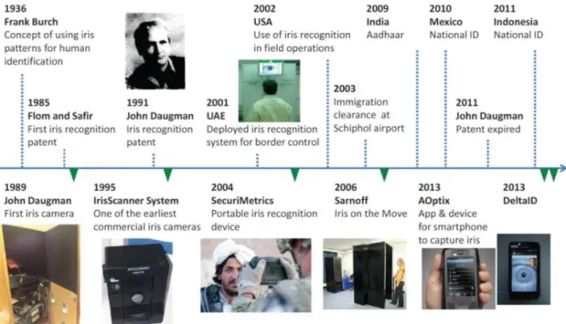
2.1 Major milestones in the history of iris recognition [1]. . . 14
2.2 Eye image showing the iris and its surroundings. . . 15
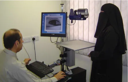
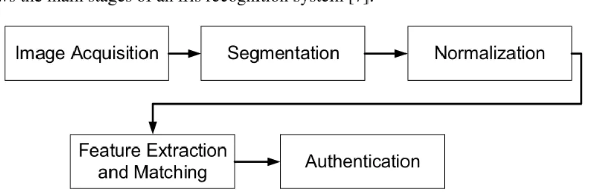
2.3 Scanning the iris for a female wearing Niqab without revealing the full face. 16 2.4 Block diagram showing the main stages in an iris recognition system. . . 17
2.5 Iris camera types: (a) Wall-mounted, (b) Handheld, (c) Visor and (d) Stand-off (SRI Sarnoff IOM PassportTM system). Image source: [3]. . . 18
2.6 Rubber sheet model [4]. . . 22
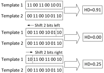
2.7 Iris normalization under different lighting conditions (a) Dilated pupil, (b) normal pupil, (c) and (d) iris images after normalization. Image source: [3]. 23 2.8 Shifting the reference template with one shift process (one left and one right) where the minimum Hamming distance is taken. . . 27
3.1 False rejection rate vs. false acceptance rate distribution [1]. . . 30
3.2 An example of ROC curve showing a verification rate of 90% at a false accept rate of 0.1%. . . 32
3.3 An example of DET curve showing a false reject rate of 5% at a false accept rate of 2%. . . 32
3.4 Biometric fusion classification [5]. . . 33
3.5 American solder performs identity check using iris recognition technol-ogy [2]. . . 36
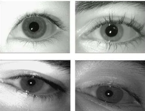
3.7 Iris samples from the MMU1 (first row) and MMU2 (second row) databases. 38 3.8 Iris samples from the UBIRIS V1 databases. . . 38 3.9 Iris samples from the UBIRIS V2 databases. . . 39 3.10 Iris samples from: (a) the UPOL database, (b) the ND-Iris-Contact-Lenses
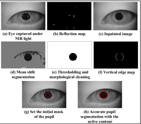
database and (c) the ATVS-FakeIris database. . . 40 4.1 Segmenting different iris images from the CASIA-Iris Lamp V4 with the
traditional snake (left column) and the GVF model (right column). The images are cropped for illustration purpose. . . 52 4.2 The steps of the pupillary detection algorithm for the iris images captured
under near infrared light. . . 54 4.3 Initial mask evolving toward the final pupil boundary with (a): the
pro-posed expanding active contour for pupil segmentation in the NIR iris images and (b) the proposed shrinking active contour for pupil segmenta-tion in visible light iris images. . . 56 4.4 Sclera detection to discard the closed eye images; the eye image in the
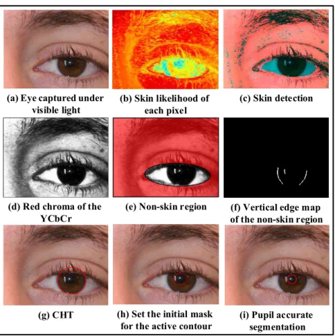
bottom row is discarded because the iris and sclera are heavily occluded. . 58 4.5 The steps of the pupillary detection algorithm for the iris images captured
under visible light. . . 59 4.6 Attenuation of eyelashes with 2D order-statistic filter. Left column shows
the original iris images while the right column shows the processed images. 60 4.7 Unsuccessful iris segmentation with: (a) the expanding active contour and
(b) the shrinking active contour. . . 61 4.8 Utilizing the Hough line transform to check the occlusion by the upper
eyelid to determine whether to use the proposed shrinking or expanding active contour. . . 62 4.9 Initial mask moving toward the final iris boundary, where the blue line
represents the detection of the upper eyelid by the Hough line transform and the dotted yellow line represents the initial mask in: (a) the shrinking active contour and (b) the expanding active contour. . . 63
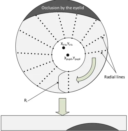
4.10 Diagrammatic representation of the noncircular normalization method for
an off-axis iris image. . . 64
4.11 Visual evaluation criteria. . . 67
4.12 Segmentation classification results from the CASIA V4, MMU2 and UBIRIS V1 databases: (a) correct, (b) fair and (c) bad. . . 68
4.13 Iris segmentation results for images from the UBIRIS V2 database using the proposed method. . . 69
4.14 ROC curves and EERs illustrate the recognition performance of differ-ent iris segmdiffer-entation methods: (a) CASIA-LAMP V4 database and (b) MMU2 database . . . 71
4.15 ROC curves and EERs illustrate the recognition performance of different iris segmentation methods: (a) UBIRIS V1 Session 1 and (b) UBIRIS V1 Session 2 . . . 72
5.1 (2,2) visual cryptography; the 50% loss in contrast can be solved when using the XOR operation. . . 85
5.2 Frequency regions in an8×8DCT block [1]. . . 86
5.3 JPEG quantization table and the selected embedding locations. . . 87
5.4 Block diagram of the proposed watermarking algorithm. . . 90
5.5 The enrolment module of the proposed method using VC. . . 93
5.6 The authentication module of the proposed method using VC. . . 93
5.7 Down sampling to retrieve the original template size. . . 94
5.8 Perceptibility of the watermarked image; (a) original image, (b) water-marked image, (c) the difference image, (d) original watermark, (e) bina-rized text and (f) the extracted watermark. . . 95
5.9 Effect of the proposed watermarking algorithm on the iris recognition performance: (a) UBIRIS V1 and (b) CASIA V4. . . 97
5.10 Effect of different manipulations on the iris recognition performance: (a) UBIRIS V1 and (b) CASIA V4. . . 99
5.11 Effects of various attacks on the extracted watermark using different wa-termarking algorithms. . . 100
5.12 Pixels distribution: (a) the original iris template and (b) the encrypted share.102 6.1 Oculo-cutaneous albinism resulting from the lack of melanin pigment. . . 113 6.2 Block diagram of the prediction model: (a) training phase (b) testing phase.115 6.3 Block diagram of the proposed cross-spectral matching framework. . . . 119 6.4 Green-yellow iris image decomposed into red, green, blue and grayscale
with the NIR counterpart. . . 120 6.5 Brown iris image decomposed into red, green, blue and grayscale with
the NIR counterpart. . . 120 6.6 The performance of the iris recognition under red, green, blue and NIR
spectra. . . 122 6.7 The color distributions of the irides of the 79 subjects in the UTIRIS
database. . . 122 6.8 The performance of the iris recognition under red, green, blue and NIR
spectra for the PolyU database. . . 123 6.9 Unwrapped iris images: (a) R channel, (b) NIR image and (c) the
pre-dicted NIR image. . . 125 6.10 Cross-channel matching of the UTIRIS database. . . 127 6.11 Cross-channel matching of the PolyU database. . . 127 6.12 ROC curves showing the iris recognition performance before and after
fusing the information of the red and NIR channels for the UTIRIS database.129 6.13 ROC curves showing the iris recognition performance before and after
List of Tables
4.1 Visual Segmentation Results of the Images in the CASIA V4, MMU2 and UBIRIS V1 Databases . . . 67 4.2 Performance comparison of the proposed method on the images from
dif-ferent databases in terms of EER. . . 73 4.3 The average computation times and the E1error reported with different
segmentation methods for the UBIRIS V2 database. . . 74 4.4 The Average Computation Times (in Sec) of Each Stage in the Proposed
Segmentation Algorithm . . . 75 4.5 Comparison among the Average Computation Times (in Sec) for
Differ-ent Iris SegmDiffer-entation Methods . . . 75 5.1 The locations array(L) used for selecting the watermarking embedding
locations . . . 88 5.2 BER and PSNR of the extracted watermark after different manipulations
using different watermarking algorithms. . . 96 5.3 Adjacent pixel correlation coefficient. . . 101 5.4 The average computation times (in sec) of each stage in the proposed
algorithm. . . 103 5.5 Comparisons with state-of-the-art biometric watermarking methods. . . . 105 5.6 Comparisons with state-of-the-art iris template protection methods. . . 105 6.1 EER (%) of different channels comparison on the UTIRIS database . . . . 123 6.2 EER (%) of different channels comparison on the PolyU database . . . . 124
6.3 The results of the cross-spectral verification using the FFNN on the PolyU database. . . 124 6.4 Experiments on different descriptors for cross-spectral matching on the
UTIRIS database. . . 125 6.5 Experiments on different fusion strategies for cross-spectral matching on
the UTIRIS database. . . 126 6.6 Cross-spectral matching comparison with different methods. . . 130
Chapter 1
Introduction
1.1
Introduction
Biometrics is the science of establishing human identity using physiological traits found in the face, a finger and the iris; or behavioral traits present in the voice and signature. The term Biometrics is derived from the Greek words “bios” and “metric” which means life measurement. Biometrics technologies generally involve measuring different sets of physiological and behavioral traits. The identity of an individual can be established by extracting measurable information from such traits which can be used later for authenti-cation [1].
Basically, biometric systems operate in the same manner. Firstly, a biometric trait is captured then a set of unique feature are extracted which are then stored as biometric tem-plates. To establish the identity, an individual unique feature is extracted and compared against a biometric database. A good biometric trait should have two characteristics: dis-tinctiveness and stability. A distinctive biometric trait is unique to an individual whereas a stable one does not change over time [2].
This chapter gives a brief overview of biometric traits and their characteristics. In addition, biometric systems and their mode of functioning are presented. Finally, the contributions of this work are listed and the structure of the thesis is outlined.
1.2
Biometric Traits
Biometric systems use different human characteristics. In biometric society, these charac-teristics are known as traits, indicators or modalities which can be classified into two main categories: physical traits and behavioral traits. Biometric authentication using physical traits aims to measure unique human characteristics such as iris texture, sclera and retina blood vessel patterns and the shape or size of palm prints. On the other hand, behavioral biometrics measure learned traits such as gait pattern, keystroke, a person’s signature and voice [2].
The choice of a suitable biometric trait can be difficult as a variety of biometric traits are available and each has its own advantages and disadvantages. Generally speaking, seven main factors should be considered when selecting a biometrics trait. These factors
can be summarized as follows [3]:
1. Universality: The trait should be available in every one accessing the system. 2. Permanence: The trait should be stable and not change significantly over time. 3. Uniqueness: The trait should be different among individuals. This means that it is
possible to distinguish the individual with the available means.
4. Collectability: It should be possible to measure the trait within a reasonable amount of time.
5. Circumvention: Refers to the possibility of imitating the trait to get an unauthorized access.
6. Acceptability: This depends on how invasive is the process of collecting the bio-metric trait. For example, retina scan has a low acceptability due to its invasive collection method and also it may reveal some medical condition about the patients such as diabetes.
7. Performance: In general, a good biometric trait should have a reasonable accuracy. No single biometric trait is considered to be ideal (meets all the aforementioned re-quirements) but some of these traits are admissible. In general, selecting a suitable trait often depends on the application.
1.3
Common Biometric Traits
Several biometric methods have been suggested during the last decades yet only a few have gained attention. Fig. 1.1 depicts the most commonly used biometric traits. A survey of these traits is presented in the next subsection.
1.3.1
Fingerprint Recognition
Fingerprint recognition is one of the most widely deployed biometrics. Fingerprint recog-nition operates by extracting unique features from a fingerprint such as ridges and minutia
Fingerprint
Face
Iris
Retina
Periocular
Sclera
Signature
Geometry
Hand
Gait
Figure 1.1: Commonly used traits in biometric systems [1].
points. After that, these features are enhanced and converted into templates to be stored in databases. Typically, multiple fingers are employed to establish a person’s identity which forms a large scale identification system. However, a large scale finger print recognition system involves extensive computational requirements especially when working in the identification mode. In addition, fingerprints may be not stable due to several factors such as aging, skin disease and abrasion due to hard work [4].
1.3.2
Face Recognition
Face recognition is a non-intrusive recognition technology which is very common in surveillance systems since a person’s face can be easily captured with video technol-ogy. Basically, face recognition either relies on geometric features such as the locations of the eyes, nose, mouth and their spatial relationships or exploits universal analysis of a face image and its intrinsic features. The face recognition performance is said to be rea-sonable under a controlled environment. However, in an uncontrolled environment face recognition performance degrades due to different factors such as illumination changes, background noise and pose variations. Therefore, it can be argued that using the face alone is not sufficient to achieve recognition with high level of confidence in a large scale environment [5]
1.3.3
Hand Geometry
A hand geometry recognition system operates by measuring certain feature in the hand such as the size and shape of the palm and fingers. The scanner of a hand geometry system cannot be used in small devices such as mobiles and laptops due to its large size. It could be argued that the geometry of the hand is not very distinctive therefore it cannot be scaled up for a large database. In addition, wearing jewelry and rings may affect the geometry information of the hand [1].
1.3.4
Iris Recognition
The iris is the colored ring that surrounds the pupil of the eye. Due to the unique charac-teristics of the iris pattern, it is considered as one of the most accurate means of human identification. The iris is a well-protected organ and appears to be stable over the life time [6]. Although the idea of utilizing the iris texture for personal identification was proposed by Frank Burch in 1936, the first working iris recognition system was implemented by Daugman in 1993 [7]. Large-scale identification systems adopt the iris biometric due to its high accuracy and speed. For example, the iris is employed as the primary biometric modality in several national identification systems such as the Aadhaar project in India, the national ID program in Mexico and the e-ktp program in Indonesia [8].
1.3.5
Periocular Recognition
The term periocular refers to the facial region that surrounds the eyes which consists of eyes, eyebrows and skin. The periocular region can be used to support iris recognition when the images are low resolution. In addition, the periocular biometric can be used to confirm the identity when part of the face image is occluded. A new sensor is not required for the periocular biometric as this region can be captured with the same face camera. Periocular recognition has a modest accuracy using good quality images with low intra-class variations [9].
1.3.6
Sclera Recognition
The sclera is the white and opaque protective layer of the eye. The sclera can be used for personal authentication because the structure of the blood vessels in the sclera is random and stable for each person [10]. Although the blood vessels of the sclera can be acquired at a distance under Visible Light (VL), sclera recognition is still challenging. This is because the vessels are often defocused and most importantly the vessels are noisy and have non-linear deformation due to the movement of the eye. Therefore, sclera recognition is often used with another biometric trait to boost the recognition performance [11].
1.3.7
Speaker Recognition
Speaker recognition refers to identifying persons based on the physiological and behav-ioral characteristics of their voice. Voice recognition can either refer to speaker recog-nition (who is speaking) or speech recogrecog-nition (what is being said). A biometric system generally focuses on speaker recognition in order to identify a person. Speaker recogni-tion can be dived into two types: text-dependent and text-independent. In text-dependent systems, the user is required to say a pass-phrase to complete the authentication while text-independent systems require a little cooperation from the user and hence they are more common in forensic applications as the enrollment could happen without the knowl-edge of the subject [2].
1.3.8
Signature Recognition
A signature belongs to the set of behavioral biometrics as each person has a unique writing style. Signature recognition can be divided into two main categories depending on the mode of operation: static and dynamic. In the static mode a scanner is used to digitize the signature and analyze its shape. This is also known as “off-line” signature recognition. On the other hand, in a dynamic or online recognition mode, the signature is acquired in real time by a digitized tablet which measures the number and length of stokes, pressure and acceleration. As a behavioral biometric, the signature is affected by time span and the emotional conditions of the person. In addition, professional forgers might imitate a person’s signature to gain unauthorized access [2].
1.3.9
Gait Recognition
Gait recognition is a relatively new biometric method aims at identifying people by the way they walk. Gait recognition is appropriate in surveillance systems as it can be used for identifying people at a distance. However, the human gait is influenced by several factors such as the walking surface, footwear and walking speed. Therefore, a gait recognition system could be vulnerable to a high false rejection rate [12]. In addition, gait recognition systems involve a relatively high computation complexity as it is a video based recognition method [13].
1.4
Modes of Functioning
Regardless of the biometric trait, the biometric recognition process follows the procedure depicted in Fig. 1.2. After a biometric trait is captured, a suitable feature extraction is applied to derive the unique biometric characteristics and convert them into mathematical templates. After that, these templates are further compared against the ones stored in a database which were collected during the enrollment process. Then authentication is granted if the comparison between the current and stored template has enough similarity. Depending on the number of comparisons between the biometric sample and tem-plates, a biometric system can work in two modes namely, verification and identification [1].
Database
Feature extraction
Biometric template Feature comparison Decision Biometric sample
Ear Iris Palmprint
Biometric traits
Figure 1.2: Typical stages of a biometric recognition system.
In the verification mode, the system verifies whether the enrolled identity is genuine or not. Therefore, the verification mode aims to answer the question: is this a person who s/he claimed to be? The user in this case is required to give an ID or a token along with the biometric sample. Therefore, the verification mode has low complexity as the comparison is carried out between the enrolled sample and the one in the database (1-to-1 match). Further, if the recognition rate is higher than a threshold value, the claim is accepted. Otherwise the enrolled sample is denied.
On the other hand, in the identification mode, the system is answering the question: is this person enrolled in the database? Since the biometric sample in the identification mode is compared against the entire database (1−to−N match), it takes more time than the verification mode. The identification is known as screening which is often used for identity deduplication or in airports and forensics to match a subject against a watch-list.
1.5
Aims of the Work
The aims of this thesis are to investigate the open issues in iris recognition and propose novel methods to tackle these problems. In particular, three novel methods are proposed to address the problems of iris segmentation, image and template protection and cross-spectral iris matching.
The objectives of this thesis are as follows:
1. To investigate a new method for iris segmentation for both VL and Near Infra-Red (NIR) iris images with the following contributions:
• a novel iris segmentation method aimed at improving the recognition perfor-mance for iris images captured under both controlled and uncontrolled envi-ronment,
• a new shrinking-expanding active contour model which integrates a new pres-sure force to segment the iris accurately and
• a new method for discarding the images with an invalid iris and limiting the search region in the non-skin parts for irises captured with visible light. 2. To develop a new framework for iris image and template protection with the
fol-lowing contributions:
• protecting the evidentiary integrity of the iris images based on a novel water-marking algorithm by embedding text data as a contextual watermark in the iris image,
• a robust iris template protection method that neither involves pixel expansion nor quality loss in the iris template and
• protecting the integrity of the smart card and stored iris template using the hash function.
3. To develop a new framework for cross-spectral iris matching with the following contributions:
• evaluating the iris recognition performance under different channels,
• a new framework for cross-spectral matching capable of matching registered and unregistered iris images captured from the same subject and
• Enhancing the iris recognition performance by multi-channel fusion.
1.6
Contributions
This thesis offers three main contributions representing significant improvements in terms of iris biometric performance, iris biometrics protection and cross-spectral matching. These contributions can be outlined as the following:
1. The study introduces a new method for iris segmentation. Hence, a new active contour model for iris and image segmentation is developed by integrating a new pressure force within the Gradient Vector Flow (GVF) model which addresses the drawbacks of previous active contour models. The movement direction of the active contour is geared based on the eyelid location. This method is capable of accurately segmenting the iris from the eye image for images taken under both VL and NIR. In addition, a novel method for discarding the images with an invalid iris and lim-iting the search region in the non-skin parts for irises captured with visible light is proposed.
2. A novel framework for iris biometric protection is proposed. This framework incor-porates two stages. The first stage is a robust watermarking algorithm to protect the evidentiary integrity of the iris images based on randomly exchanging four middle band coefficient pairs of the Discrete Cosine Transform (DCT) to embed text data as a contextual watermark in the iris image. The second stage is a Visual Cryptogra-phy (VC) scheme for iris template protection that neither involves pixel expansion nor quality loss in the iris template. The integrity of the stored iris template is also guaranteed by using the hash signatures.
3. A novel framework for cross-spectral iris matching. This framework is capable of matching registered and unregistered iris images in different lighting conditions. This work is amongst the first attempts in the literature to investigate the problem of VL to NIR iris matching (and vice versa) on iris images belonging to the same sub-ject. In addition, the differences in iris recognition performance under NIR and VL imaging are investigated. Furthermore, enhancing the iris recognition performance with multi-channel fusion is attained.
1.7
Thesis Outline
Three novel methods are proposed in this work covering iris segmentation, protection and cross-spectral matching. These novel methods are discussed in Chapter 4, Chapter 5 and Chapter 6, respectively. The thesis is organized as follows:
Chapter 2 presents an overview of the anatomy and properties of the human iris from image acquisition to feature matching. Accordingly, a brief overview of camera types in the acquisition stage was given. In addition, the stages of the iris recognition system are presented in detail and the baseline algorithms in each stage are given.
Chapter3 presents the a brief introduction on performance evaluation for a biometric system. In addition, this chapter lists some of the public deployment iris based system used on a national scale. Moreover, a survey of the publicly available iris databases is given.
Chapter 4 presents the proposed iris segmentation method. A detailed literature review related to iris segmentation is given. The snake and the GVF active contours are presented along with their drawbacks. After that the proposed active contour is introduced based on adding a new pressure force to the GVF active contour to form a shrinking/expanding model for iris segmentation for iris images captured under both the visible and infra-red light. Moreover, a novel method is proposed for discarding the images with an invalid iris and limiting the search region in the non-skin parts for irises captured with visible light.
Chapter 5 presents the proposed iris image and template protection method. After the literature review, the chapter is divided into two parts. The first part presents the proposed watermarking algorithm for protecting the evidentiary integrity of the iris images based on exchanging multiple middle band coefficients of the DCT blocks using text data as a contextual watermark. The second part presents the template protection method which works by dividing the iris templates into two shares based on VC. After decomposing the iris template into two shares, one share is given to the user on a smart card and the other share is stored in the database along with a signature generated by a hash function. Furthermore, the integrity of the stored iris template is also guaranteed by using the hash signatures.
Chapter 6 focuses on cross-spectral iris matching. In this chapter a new framework is introduced for cross-spectral iris matching capable of matching registered and unregis-tered iris images taken under VL and NIR. Two methods are proposed for cross-spectral iris matching. The first method was designed to work with registered iris images which adopted a Feed Forward Neural Network (FFNN) to synthesize the corresponding NIR images from the VL images to perform the verification. The second method is capable
of working with unregistered iris images based on integrating the Gabor filter with dif-ferent photometric normalization models and descriptors along with decision level fusion to achieve robust cross-spectral matching. In addition, this chapter investigates the per-formance of iris recognition under different channels. Furthermore, enhancing the iris recognition performance with multi-channel fusion is attained.
Finally, Chapter 7 draws the overall conclusions and provides directions for future work.
Chapter 2
2.1
Background of Iris Recognition
“For purposes of rapid and reliable person identification,...it is hard to imagine one (unique identifier) better suited than a protected, immutable, internal organ of the eye (iris), that is readily visible externally and that reveals random morphogenesis of high statistical complexity”[7, p.1160].
2.1.1
History
Efforts to create a reliable means for human authentication based on the iris texture ago back to the early 1930s when the ophthalmologist Frank Burch noticed highly detailed and unique features in the iris which stayed unchanged over a long time. This idea remained as a science fiction until two ophthalmologists Leonard Flom and Aran Safir patented Burch’s concept but they were unable to develop an automated recognition system. It was not until 1993 when John Daugman developed the first automated iris recognition system. Daugman’s method is considered the baseline for all current iris recognition systems [14]. Fig. 2.1 shows the major milestones in the history of iris recognition.
In 2002, iris recognition technology was manifested by disclosing the identity of the missing Afghan girl. This story goes back to 1984 when a photographer went to Pakistan to document the suffering of the Afghanistan’s refugees following the bombing by the Soviet Union. During his visit he captured a photo of a young girl which then became very famous and printed on the cover of the National Geographic magazine [15].
Seventeen years later, National Geographic TV started a search for the Afghani girl but several women turned out and claimed to be that girl. Unfortunately, there was no way to establish the identity as there was no recorded name of the young Afghani girl and her face would have changed significantly due to aging. The team managed to confirm the correct identity with the help of iris recognition where the iris patterns were matched from the photograph of 1984 to a women called Sharbat Gula with a very tiny probability of error (10−15) from her left eye [16].
2.1.2
Anatomy and Properties of the Human Iris
The iris is the colored ring that surrounds the pupil. A front view of an iris image is shown in Fig. 2.2. The iris controls the amount of light that enters the pupil. The pupil size can vary from 10% to 80% of the iris diameter. The average radius of the iris is around 6mm [6].
The structure of the iris is completed by the eighth month of gestation. Although the color of the iris may change during the first postnatal years, the structure itself is stable throughout the human’s life. The iris color is controlled by the density of the melanin pigment in its anterior layer. On the other hand, the meshwork of the elastic ligament forms the texture of the iris. The chromophore of the human iris is noticeable under VL and it becomes hidden under the NIR light. Therefore, with dark pigmented irides, stromal features of the iris are only revealed under NIR and they become hidden in VL so the information related to the texture is revealed rather than the pigmentation [14].
As mention is Section 1.2, a good biometric trait should have several characteristics to provide a reliable recognition. In addition to those characteristics, the iris enjoys further advantages over other biometric traits. For instance, the iris is a well-protected organ and its physiological response to light offers robustness to fake samples. Moreover, it cannot be surgically modified without risks to vision. Furthermore, iris technology is deemed to be very hygienic as there is no physical contact compared to other biometric based on finger or palm print. This property allows iris images to be captured from a distance without physical contact which makes the iris suitable for forensics applications. Besides, iris recognition technology is culturally accepted by the people of some countries where it is common to cover the face by Niqab. (Fig. 2.3).
2.2
Iris Recognition System
Generally, an iris recognition system comprises of five main stages: image acquisition, iris segmentation, iris normalization, feature extraction and feature matching. Fig. 2.4 shows the main stages of an iris recognition system [7].
Image Acquisition Segmentation Normalization
Feature Extraction
and Matching Authentication
Figure 2.4: Block diagram showing the main stages in an iris recognition system.
2.3
Image Acquisition
Image acquisition plays a vital role in iris recognition. Poor image condition has been shown to degrade iris recognition performance and badly affect the intra-class similarity. Fig. 2.5 shows different types of iris camera. There are four main types of camera for iris acquisition [17]:
1. Access control: A wall-mounted camera that captures the iris with a medium focal length and requires user cooperation.
2. Handheld: A portable camera with a small focal length and typically used for access control.
3. Dual-eye visor: A mobile camera that covers both eyes and requires active user cooperation.
4. Stand-off camera: A camera with a large focal length which requires less user co-operation and can capture images on the move.
The aforementioned cameras have the same operation manner: An infra-red light is emitted from a source (with wavelengths between 700-900nm) and the iris image is
cap-Figure 2.5: Iris camera types: (a) Wall-mounted, (b) Handheld, (c) Visor and (d) Stand-off (SRI Sarnoff IOM PassportTM system). Image source: [3].
tured with the camera. The human eye does not respond automatically to the NIR illumi-nation compared with the VL in terms of blinking and pupil contraction. Therefore, there is an illumination limit to the NIR irradiance which has been set to 10mW per square centimeter. Hence, NIR devices should be placed relatively close to the subject. On the other hand, to avoid pupil dilation, iris recognition systems recommend that a specific illumination level is set.
2.4
Iris Segmentation
Iris segmentation is an essential module in an iris recognition system as the performance of the system is highly dependent on this step and errors can lead to misclassification dur-ing authentication. This step involves isolatdur-ing the iris structure from other components in an eye image, including the pupil, sclera, eyelashes, eyelids and reflections. A robust segmentation technique is needed as the errors which happen at the segmentation stage cannot be corrected later and yield a false rejection.
Several iris segmentation algorithms have been proposed. These algorithms can be broadly classified into two categories of iris segmentation: 1) Iris segmentation with the classical circular approaches and their improvements, 2) Iris segmentation with noncir-cular approaches. A brief overview of the main methods for iris segmentation is given next.
2.4.1
Hough Transform
The Hough transform is a famous computer vision algorithm that can be employed for determining the parameters of different geometric shapes including lines and circles. For iris segmentation, the Circular Hough Transform (CHT) can be utilized for inferring the radius and center of the iris in images which are captured under a controlled environment. Basically, the CHT involves these steps: After generating the edge map, a vote is cast in the Hough space for the parameters of circles passing through each edge point. Any circle can be defined with the center coordinates(xc, yc)and the radius r. Hence in the Hough space, a maximum point with the largest number of intersection will correspond to the radius and center coordinates of the best circle [18]. Although the CHT is robust to the gaps and noise presence in the image, it has a high computational complexity of O(N3)and suffers from the thresholding problem [19].
2.4.2
Integro-Differential Operator (IDO)
Daugman proposed to use the IDO for iris and pupil localization in the eye image. The IDO can be defined by:
maxr,x0,y0 Gσ(r)∗ ∂ ∂r I r,x0,y0 I(x, y) 2πr ds (2.1)
where I(x, y) is the eye image, ∗ denotes the convolution operator, r is the radius of the search range, Gσ(r) is a Gaussian smoothing function and s is the contour of the circle given by (x0, y0), and r. The IDO varies the radius and center position of the circular contour until finding a path where there is maximum change in pixel values. The operator is applied iteratively while reducing the amount of noise in order to attain a precise localization [7].
Although the IDO does not suffer from the thresholding problem, it can fail to detect circles in the presence of noise in the eye images especially when images are captured under VL.
2.4.3
Active Contour
Noncircular approaches are effective in iris segmentation because iris boundaries appear to be noncircular especially under uncontrolled environments and in the presence of eye-lids. Therefore, an active contour is an ideal candidate for this purpose [20]. An active contour curve moves from initial mask until equilibrium is reached. The position of the active contour is changed by two opposing forces: an internal force, which controls the deformability of the curve, and an external force, which is derived from the image energy. Each vertex in the active contour force is moved between timetandt+ 1by:
vi(t+ 1) =vi(t) +Fi(t) +Gi(t) (2.2)
whereFiis the internal force,Giis the external force andviis the position of vertexi. For segmenting the iris region, the internal force is initialized so that the contour evolves from initial state until the energy function is minimized when the curve is on the iris boundary [21].
2.4.4
Other segmentation methods
Other noncircular segmentation methods such as ellipse fitting and the parabolic Hough transform typically extend the previous segmentation methods [22, 23]. The thresholding based segmentation method works on the assumption that the iris/pupil can be separated from eye image based on the contrast difference. This method may work for the iris im-ages captured under NIR because there is high contrast difference between the iris and pupil. However, it fails to segment visible iris images due to the low contrast difference and the presence of reflections. In addition, the thresholding based method requires a suitable threshold to be found for each imaging condition which could be challenging. Almost all the previously stated methods, however, require a fine tuning with large com-putation time and cannot be generalized for all the image conditions [24].
2.5
Normalization
After segmenting the iris, the next stage is to transform the segmented iris to the dimen-sionless polar coordinates in order to remove the dimensional inconsistency between the images due to pupil dilation with different lighting conditions. Other sources of inconsis-tency include camera or head rotation and varying capturing distance. The normalization stage aims to solve the inconsistency due to pupil dilation but inconsistency due to image rotation will be addressed at the matching stage [6]. Almost all the current iris recognition systems adopt the rubber sheet method or its modifications for iris normalization which is explained next.
2.5.1
Rubber Sheet Model
Daugman proposed to use the rubber sheet method for iris normalization [7]. This model remaps each point in the iris image to the polar coordinates(r, θ)whererhas an interval
[0,1]andθis angle in[0,2π]as shown in Fig. 2.6:
Figure 2.6: Rubber sheet model [4]. polar representation can be modeled by the following equations:
I(x(r, θ), y(r, θ))→I(r, θ) (2.3) x(r, θ) = (1−r)xp(θ) +rxi(θ) (2.4) y(r, θ) = (1−r)yp(θ) +ryi(θ) (2.5) with xp(r, θ) = xpo(θ) +rpcos(θ) (2.6) yp(r, θ) = ypo(θ) +rpsin(θ) (2.7) xi(r, θ) = xio(θ) +ricos(θ) (2.8) yi(r, θ) = yio(θ) +risin(θ) (2.9)
where I(x, y) is the iris image, (x, y) are the original Cartesian coordinates and (r, θ)
are the corresponding normalized polar coordinates. The radius of the pupil and iris are respectively defined by rp and ri while xp(θ), yp(θ) and xi(θ), yi(θ) represent the coordinates of the pupillary and iris boundaries in the direction θ. Further, (xp0, yp0) and (xi0, yi0) represent the centers of the pupil and iris respectively [7]. After that, a constant number of points are chosen along each radial lines to produce a fixed dimension normalized iris sheet. Examples of normalized iris images are shown in Fig. 2.7 .
As mentioned earlier, the rubber sheet method mitigates inconsistency due to the pupil dilatation but it does not compensate for rotational variations. Such rotational inconsis-tency will be addressed at the matching stage.
Figure 2.7: Iris normalization under different lighting conditions (a) Dilated pupil, (b) normal pupil, (c) and (d) iris images after normalization. Image source: [3].
2.5.2
Virtual Circles
Boles and Boashash [25] proposed to scale iris images to have a constant diameter to mitigate the dimensional inconsistency. After scaling, when the images to be compared have the same dimensions, concentric virtual circles are used as reference boundaries for feature extraction with the origin at the center of the pupil. After that, the same normalization resolution is assigned for the iris images so that each iris has the same number of data points. However, this method may fail when there is a big variation in pupil size within the iris images. In addition, it is not clear how to deal with the rotation invariance.
2.6
Feature Extraction
Feature extraction aims at extracting the most discriminating information from the iris image in order to provide accurate recognition. Nearly all iris recognition systems employ a band pass filter to generate the iris template and most of the currently deployed iris recognition systems adopt Daugman’s method for feature extraction. Several alternative methods have been proposed but their performance is not as high as Daugman’s and their recognition performance have not been tested on a large scale databases [24].
Most feature extractors used in iris recognition systems generate binary templates due to the following advantages[7]:
• Solid storage: iris templates (iriscode) have small storage (2048 bits in [6]) com-pared to other biometrics technologies which typically require more complex data representation.
• Fast comparison: rapid comparison can be executed when dealing with a binary representation. These operation can be executed in parallel to handle multi-millions comparison in one second.
Next, Daugman’s method for feature extraction will be presented.
2.6.1
Gabor Filter
A Gabor filter is a linear filter used for feature extraction and texture analysis. A Ga-bor filter is created by modulating a sine/cosine wave with a Gaussian signal. This will provide a perfect conjoint localization in space and frequency [26].
Signal decomposition is achieved with a quadrature pair of Gabor filters. While the real part is constructed by modulating a Gaussian signal with a cosine, the imaginary part is constructed by modulating a Gaussian signal with a sine wave. The real and imaginary parts are also known as the even and odd components. The bandwidth of the filter is controlled by the width of the Gaussian signal while the frequency of the filter is specified by the frequency of the sine/cosine waves [26].
Daugman employed a 2D Gabor filter for encoding the iris texture [7]. A 2D Gabor filter can be represented as:
G(x, y) =e−π[(x−x0)2/α2+(y−y0)2/β2]e−2πi[u0(x−x0)+v0(y−y0)] (2.10)
where(x0, y0)represents the pixel coordinates in the iris image,(α, β)specify the effec-tive width and length while(u0, v0)specify modulation which has a spatial frequency of ω =pu2
0+v02 .
In Daugman’s method, the phase output of the filter is quantized into four levels ac-cording to the quadrant of the complex plane of the filter phase information. Oppenheim
and Lim [27] show that the phase information provides the most significant information within an image. Hence, taking the phase information rather than amplitude in the iris image allows for robust encoding while discarding the redundant information such as il-lumination and lighting variations. These four levels are represented by two bits so that each pixel in the normalized iris image corresponds to two bits in the encoded template. Therefore, a normalized iris template with a resolution of20×240can be represented by a 9600 bit template. Therefore, the iris image can be represented by a compact 1200 byte template that allows an efficient and fast comparison of iris templates.
2.6.2
Log-Gabor Filters
A Gabor filter has the disadvantage that the even part of the filter will have a DC compo-nent [28]. To solve this drawback a Log-Gabor filter can be used. The frequency response of a Log-Gabor filter can be represented by:
G(f) =exp[−(log(f /f0))
2
2(log(σ/f0))2
] (2.11)
wheref0 represents the center frequency andσgives the bandwidth of the filter [28].
2.7
Matching
After generating the iris templates, a metric should be employed to measure the similarity. This metric should give one range of values when comparing templates generated from the same eye (intra class) and another range when comparing templates belonging to different eyes (inter class). Based on this metric, a decision can be made to decide whether to authenticate the person or not. In principle, any type of classifier can be used for this purpose such as Euclidean distance or Hamming distance as explained next.
2.7.1
Weighted Euclidean Distance
The Weighted Euclidean Distance (WED) is used to measure the similarity between two integer templates. The WED is given by [29]:
W ED(k) = N X i=1 (fi−f (k) i )2 (σ(k))2 (2.12)
where fi is the ith feature of the current iris template and fi(k) is the ith feature of the compared templatekwhileσ(k)is the standard deviation of theithfeature in the template k. The best match is found with the template corresponding to the minimum value ofk.
2.7.2
Hamming Distance
The Hamming Distance (HD) is the matching metric employed by Daugman to measure the similarity between two templates. For the bit patterns X and Y, theHDcan be defined as the sum of disagreeing bits over the total number of bits in template. For a binary template, the number of the disagreeing bits can be expressed as the sum of the exclusive-OR bits betweenX andY divided by the total number of bits (N) as follows [6]:
HD= 1 N N X i=1 Xi(XOR)Yi. (2.13)
If there is no correlation in the bits withing the templates, the HD between templates should be around 0.5. This is because the bits in independent patterns are random and therefore half of them will agree and half will disagree. On the other hand, if the two templates belong to the same eye the bits will be highly correlated and the HD should be close to zero.
In order to include the actual iris region and cancel the effects of eyelids and eyelashes, a noise masking is incorporated within the HD equation. This mask contains “0” bits which correspond to the true iris region and “1” bits which correspond to the noise. Hence, the modified HD equation is given by [6]:
HD= 1 N −PN k=1Xnk(OR)Y nk N X j=1 Xi(XOR)Yi(AN D)Xn0i(AN D)Y n 0 i (2.14)
11 00 11 00 10 01 Template 1 Template 2 00 11 00 10 01 10 HD=0.91 00 11 00 10 01 10 Template 1 Template 2 00 11 00 10 01 10 HD=0.00 Shift 2 bits left
Shift 2 bits right 10 11 00 11 00 10 Template 1
Template 2 00 11 00 10 01 10
HD=0.25
Figure 2.8: Shifting the reference template with one shift process (one left and one right) where the minimum Hamming distance is taken.
whereXi andYi are the two iris templates to be compared,Xni and Y ni are the corre-sponding noise masks whileN is the number of bits in each template.
To address the rotational inconsistencies, the iris template is shifted left and right multiple number of times and the HD is calculated then the minimum value is taken. Each filter generates two bits of data corresponding to one pixel in the iris pattern. Therefore, the number of bits to be moved in each shift equals twice the number of the employed filter. The actual number of shifts required to overcome the rotational inconsistencies is governed by the maximum angle of difference between the two normalized iris images [6]. Figure 2.8 illustrates the shift process.
2.8
Summary
In this chapter a brief history of iris recognition was presented showing the main mile-stones in iris recognition development. In addition, the anatomy and properties of the human iris were presented from image acquisition to feature matching. Accordingly, a brief overview of camera types in the acquisition stage was given. After that, the main stages in iris recognition namely: segmentation, normalization, feature extraction and matching were presented and their corresponding algorithms were explained.
The next chapter presents a brief overview on performance evaluation in a biometric system. In addition, a survey of the publicly available iris databases will be given.
Chapter 3
3.1
Biometric System Evaluation
The evaluation of a biometric system is a challenging task as it not only involves engi-neering but also other fields such as computer science, statistics along with the end user community and system designers. Therefore, to establish a comprehensive understanding of a biometric system, the following points should be addressed [1]:
• The availability, maintainability and reliability of the biometric system.
• The error rates of the system in different applications (matching performance).
• The vulnerabilities of the biometric system and security issues.
• The user acceptability of the applied biometric system and privacy issues.
• The cost of implementing and running the system while judging the expected ben-efits.
There is no existing evaluation framework which can address all the aforementioned points simultaneously. The next section will focus on the matching performance of a biometric system.
3.2
Matching Performance
Biometric system performance can be measured by its ability to identify authorized sub-jects and reject unauthorized individuals. This can be achieved by measuring the similar-ity score for the output of a test. Hence, comparing the output score to a threshold results in an accept or reject decision. This decision could be erroneous in two cases. The first is false rejection when a true score is rejected and it is also known as False Reject Rate (FRR). The second case is false acceptance when an imposter is accepted and it is also known as False Accept Rate (FAR) [30].
An FRR of 1% is a result of one failed authentication attempt by the genuine user in each 100 authentication attempts. Most of the FRR error results from the incorrect interaction between the user and the biometric sensor. This can be easily corrected by asking the user to perform the authentication process again. This simulates entering a
wrong password in a password-based authentication system where the user is allowed to have another try. On the other hand, An FAR of 0.01% indicates that on average 1 in each 10000 authentication attempts by random imposters will be successful [30].
To generate the genuine scores in a biometric system which hasN users and each user hasmsamples, the samples from the same user have to be compared . On the other hand, to generate the imposter scores, samples from two different users have to be compared. Therefore, the total number of genuine scores will equal to (m(m−1)N)/2while the number of imposter scores will equal to(N(N −1)m2)/2[1].
The most common way of measuring the performance of biometric systems is by measuring the rate that both FAR and FRR become equal to each other which is known as the Equal Error Rate (EER). The EER is often used when the performance is needed to be summarized by a single number. The more accurate the biometric system the lower the EER. The distribution of FAR vs. FRR and EER are shown in Figure 3.1.
Genuine distribution Imposter distribution FAR FRR EER Decision threshold (t) P ro b a b il it y ( p ) Matching score (s)
3.3
Performance Graph
The FAR and FRR give the system performance at a specific score threshold. However, this evaluation is limited as the values of the threshold are only related to a specific algo-rithm and cannot be compared among different systems. In addition, it is often necessary to measure the performance over a range of thresholds. Therefore, it is essential to de-velop a method that is able to compare the performance independently of match scores [1].
This can be achieved by plotting the error rates over a range of thresholds with respect to the FAR and FRR. In this context, two standard plots are known in the literature namely: Receiver Operating Characteristic (ROC) curve and the Detection Error Trade-off (DET).
3.3.1
ROC Curves
In order to visualize the error trade-off, the FRR and FAR can be plotted over a range of thresholds. In this case all the scores should be normalized so that a unique threshold can be applied to all the genuine scores. This plot is known as the ROC curve. The ROC curve is a plot of the FAR versus the Genuine Acceptance Rate (GAR) which is calculated as:
GAR = 1−F RR (3.1)
A plot of ROC curve is depicted in Figure 3.2. In this figure the x-axis has a logarith-mic scale to better distinguish the values of FAR.
3.3.2
DET Curves
The DET curve is similar to the ROC curve but the y-axis is the FRR as shown in Fig. 3.3. The choice between the ROC and DET curves is essentially aesthetic as both curves contain similar information. However, DET curves are often used in speaker recognition systems rather than ROC curves. This is because plotting error rates on both axes will give a uniform distribution to both errors and help to highlight the difference in a similarly performing systems [30].
False Accept Rate
Veri
fication rate (
1-FRR
)
Figure 3.2: An example of ROC curve showing a verification rate of 90% at a false accept rate of 0.1%.
Figure 3.3: An example of DET curve showing a false reject rate of 5% at a false accept rate of 2%.
3.4
Biometrics Fusion
Biometric system that depends on a single source of data may fail to meet the requirements when working in challenging conditions. Therefore, fusion multiple level of sources can boost the performance and compromise for such limitations.
Generally speaking, fusion of biometric data can be divided into two broad categories: fusion before matching and fusion after matching (Fig. 3.4). Fusion before matching can be either performed at the sensor level or feature level. Sensor level fusion requires multiple sources of the biometric samples (raw data) and hence it can only be applied to a multi-sensors biometric system [1]. Feature level fusion works by combining multiple feature sets into a single feature vector. This feature vector can be either homogeneous (from the same feature extraction algorithm) or non-homogeneous (from different feature extraction algorithm). Feature from different sources need to be converted to the same representation to facilitate the fusion process [1].
Figure 3.4: Biometric fusion classification [5].
On the other hand, fusion after matching can be divided into score level, rank level and decision level. Combining the final output scores of multiple biomtric matchers is known as score level fusion. It is easy to consolidate the scores resulted from similar classifier as these scores are homogeneous. However, if the output scores of m
![Figure 3.5: American solder performs identity check using iris recognition technology [2].](https://thumb-us.123doks.com/thumbv2/123dok_us/1107635.2647372/57.892.269.714.126.462/figure-american-solder-performs-identity-check-recognition-technology.webp)