Linear Kalman Filter-Based Grid Synchronization
Technique: An Alternative Implementation
Hafiz Ahmed,
Senior Member, IEEE,
Samet Biricik,
Senior Member, IEEE,
Mohamed Benbouzid,
Fellow, IEEE
Abstract—Grid synchronization techniques play a significant role in integrating renewable energy sources to the electric power grid. In this context, estimating the phase and frequency of the grid voltage signal is an interesting problem. Out of various techniques available in the literature, Linear Kalman Filter (LKF) is one of the most popular one. In this paper, we propose an alternative implementation of the LKF for grid synchronization application. The proposed implementation uses a linear paramet-ric model of the grid voltage signal including DC offset. It does not involve any quadrature signal generation, rather it works by estimating the phase angle. This helps to estimate the unknown grid frequency directly from the phase angle. This clearly differ-entiates the proposed alternative implementation with respect to the existing implementations. Performance improvement by the proposed technique is verified extensively through comparative numerical simulation and experimental studies. Comparative results demonstrate the suitability of the proposed technique with respect to other state-of-the-art techniques namely Second-Order Generalized Integrator Phase-Locked Loop (SOGI-PLL) and Enhanced Phase-Locked Loop (EPLL).
Index Terms—Grid Synchronization, Linear Kalman Filter, DC Offset, Phase Estimation, Frequency Estimation
I. INTRODUCTION
Phase and frequency play a fundamental role in the success-ful and efficient operation of a number of power electronic systems. Some example of such systems are: grid-connected renewable energy sources [1]–[4], grid-connected AC/DC rec-tifier [5], vehicle-to-grid operation of electric vehicle [6], sensitive load protection through dynamic voltage restorer [7], islanding detection [8] etc. All these applications rely on grid synchronization technique which extracts the phase and frequency of the grid voltage signal.
Grid synchronization technique is an active research area and many techniques have been proposed so far. Existing literature on this topic can be broadly classified into time-domain and frequency-time-domain based methods. Some pop-ular grid synchronization techniques are: Discrete Fourier Transformation (DFT) [9], least-squares [10], [11], maximum Manuscript received XXX XX, 2020; revised XXX XX, 2020; accepted XXX XX, 2020. Date of publication XXX XX, 2020; date of current version XXX XX, XXXX. This work was supported in part by the Royal Society under grant RGS\R2\192245. Paper no. TII-20-0113.R2. (Corresponding author: Hafiz Ahmed.)
H. Ahmed is with the School of Engineering and the Built Environment, Birmingham City University, Birmingham B4 7XG, United Kingdom (e-mail: [email protected]).
S. Biricik is with the Department of Electrical and Electronic Engineering, European University of Lefke, Lefke 99728, Turkey, and also with the School of Electrical and Electronic Engineering, Technological University Dublin, Dublin D08 X622, Ireland.
M. Benbouzid is with the University of Brest, UMR CNRS 6027 IRDLs, 29238 Brest, France, and also with the Logistics Engineering College, Shanghai Maritime University, Shanghai 201306, China.
likelihood estimator [12], [13], second-order generalized in-tegrator (including linear and nonlinear variants) [14]–[16], adaptive notch filter [17], demodulation [18], [19], open-loop approaches [20], [21], complex coefficient filter [22], delayed signal cancellation [23], Phase-Locked Loop (PLL) [24]– [29], Frequency-Locked Loop (FLL) [16], [30]–[33], adaptive observer [34]–[36], Kalman filter [10], [37], to name a few.
For periodic signals, DFT [9] can be a very suitable technique. Although standard implementation of DFT can be computationally expensive, however, a recursive imple-mentation can reduce the computational complexity a lot. DFT suffers from accumulation error. This can be solved through additional computational cost. Spectral leakage is another issue DFT faces in the case of non-periodic signal. Spectral leakage information can be efficiently used to estimate the unknown frequency of the grid voltage signal. However, large window size can be an issue. Least-squares [10], [11] generally work by obtaining linear parametric model of the grid voltage signal. In addition to computational complexity, tuning the forgetting factor can be tricky. Moreover, frequency adaptive implementation requires a separate PLL/FLL or some other additional frequency identification technique. Maximum likelihood estimation [12], [13] uses statistical approaches and can be computationally expensive. Moreover, extension to grid voltage with harmonics is not straightforward.
Using linear harmonic oscillator as the underlying model, second-order generalized integrator (including linear and non-linear variants) [14]–[16] works by generating quadrature signals. Then by using PLL/FLL, frequency adaptive estima-tion of the single-phase grid voltage can be obtained. The performance may degrades in the presence of noise. Adaptive notch filter [17] and delayed signal cancellation [23] are two other quadrature signal generator based techniques. Adaptive observers [34]–[36] also generate quadrature signals. However, the unknown frequency identification law is obtained through Lyapunov function-based approach. This enables to achieve global asymptotic convergence for the estimated parameters. However, adaptive observers do not employ any gain normal-ization technique. This may be a bottleneck to provide Low Voltage Ride Through (LVRT) capability for grid-connected converters. Demodulation [18], [19] uses the principle of demodulation. By multiplying the grid voltage signal with two other time-varying signals, demodulated voltages can be obtained. In addition to the fundamental component, de-modulated voltages also contain two times the fundamental frequency component. Then by applying high order low-pass filters, the undesired frequency components can be removed. However, low-pass filter have non-ideal characteristics. As such, filtering may introduce large attenuation of the signal
By passing the DC signal through a low-pass filter (usually a proportional-integral controller), the unknown frequency can be estimated. Unlike three-phase system, single-phase system has only one measured signal i.e. grid voltage. To implement Park transformation, a virtual orthogonal signal needs to be generated. Performance of PLL depends largely on the proportional-integral controller tuning. Fast dynamic response can come at the cost of accuracy. FLL [16], [30]–[33] can be an effective solution to address the fast dynamic response. FLL generally exploits the phase relationship between the input variables to estimate the unknown frequency. Since no low-pass filtering is involved in estimating the frequency, FLL can be made fast responsive. However, this comes at the cost of reduction in harmonic filtering property.
Kalman filter [10], [37] is another popular approach avail-able in the literature. Unlike many of the previously mentioned techniques, Kalman filter explicitly considers the noise present in the signal and can provide optimal estimation in the pres-ence of Gaussian noise. Both linear [10], [37] and nonlinear variants of Kalman filter are available in the literature. In the case of linear Kalman filter, an additional frequency estimation block in the form of PLL/FLL is required. Nonlinear Kalman filter considers the unknown frequency as an additional state variable and converts the parameter estimation problem into state estimation problem using extended state-space model. Nonlinear Kalman filter is computationally expensive and can be highly sensitive to initial conditions and noise parameter tuning. As such in this paper, the focus is on Linear Kalman Filter (LKF). Frequency adaptive LKF generally works either by using the concept of synchronous reference frame PLL (i.e. Park transformation followed by PI-type low-pass filtering) or FLL. Both cases require orthogonal signal generation. In this paper, we propose the application of linear parametric model of the grid voltage signal that explicitly considers DC offset. Using the linear parametric model, the phase angle can be extracted directly using the LKF. Then using phase-based frequency estimation idea similar to [23], the frequency can be directly estimated without using any Park transformation. Moreover, this approach has one less parameter to tune with respect to PLL-based LKF. This clearly differentiates proposed alternative implementation of the Kalman filter with respect to existing implementations [10], [37]. Moreover, as the proposed implementation directly estimates the phase-angle (i.e. θ) not the instantaneous phase (i.e. ωt+θ) like PLL-based LKF, the proposed implementation can be considered as less sensitive to phase jumps.
The rest of the article is organized as follows: Sec. II describes in detail the proposed alternative implementation of Kalman filter. Comparative numerical simulation and experi-mental studies are given in Sec. III. Sec. IV concludes this paper. Existing implementation of the linear Kalman filter-based grid synchronization technique is given in the Appendix.
=V0+ sin(ωt)Vcos(θ) +cos(ωt)V sin(θ) (1)
where V is the amplitude,V0 is the DC offset, ω = 2πf is
the grid frequency, θ is the phase,and Φ = ωt+θ is the instantaneous phase. By considering x = [x1 x2 x3]T =
[V0 V cos(θ)V sin(θ)]T, the grid voltage dynamics in
state-space form can be written as:
˙ x= 0 0 0 0 0 −1 0 1 0 | {z } A x (2a) y= 1 sin(ωt) cos(ωt) | {z } C x (2b)
Model (2) is developed in continuous-time. Let us consider, t = nTs, with Ts = 10−4 being the sampling period. This
corresponds to a sampling frequency of10kHz.This value is widely used in the literature [3], [20]. Then, model (2) can be discretized by using Euler method as:
An ≈ 1 0 0 0 1 0 0 0 1 , Cn = 1 sin(φ) cos(φ) .
withφ=ωnTs. The model (2) in discrete-time can be written
as:
xn+1=Anxn+vn (3a)
yn=Cnxn+wn (3b)
whereE[vnvTn] =Qn =qI3 is the covariance of the process
noise, E[wnwnT] = Rn = r is the covariance of the output
noise, and it is assumed that the process and measurement noises are independent. Assuminga prioriknowledge ofqand r, the conventional recursive implementation of the Kalman filter is given in the following [38]:
Prediction: ˆ xn|n−1=Anxˆn−1|n−1, (4a) Pn|n−1=AnPn−1|n−1ATn +Qn, (4b) Correction: Kn=Pn|n−1CnT CnPn|n−1CT+Rn −1 , (5a) ˆ xn|n= ˆxn|n−1+Kn y−Cnxˆn|n−1 | {z } en , (5b) Pn|n= (I−KnCn)Pn|n−1(I−KnCn)T +KnRnKnT. (5c)
Kalman Filter
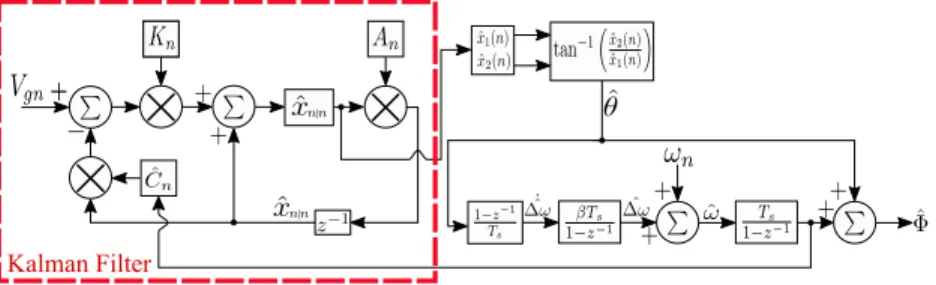
Figure 1. Proposed implementation of the Kalman filter-based frequency estimation technique.
In eq. (4) and (5), n is the sampling instant,ˆrepresents estimated value,eis the output estimation error,P is the error covariance matrix, and Kn is the Kalman gain vector.
Then the implementation of Kalman filter given in eq. (4)-(5) using the model (3) is straightforward. Unlike standard implementation of the Kalman filter as described in the Ap-pendix, the proposed implementation does not estimate the in-phase and quadrature-in-phase signal of the grid voltage. Rather it estimates two DC signal (i.e.V cos(θ)andVsin(θ)) involving the phase angle of the grid voltage signal. From the estimated states, the phase angle can be estimated as:
ˆ θ= arctan xˆ 3 ˆ x2 (6) The output eq. (3b) requires the estimated frequency ω. Toˆ
estimate the frequency, the estimated phase angle can be very useful. In the steady-state, the estimate represents the phase angle only. However, during transient period, the estimated phase angle contains the deviation from the nominal frequency information as well. Then by passing it through a simple first-order differentiator, the frequency deviation dynamics can be obtained as: ˙ˆ ∆ω=1−z −1 Ts ˆ θ (7)
where∆ˆωis the deviation from the nominal frequency. Equa-tion (7) implements a first-order Euler differentiator which can be sensitive to measurement noise. To overcome this issue, the differentiator can be coupled to a simple first-order Low-Pass Filter (LPF). In this case, the frequency deviation dynamics can be written as:
˙ˆ ∆ω= µ 1−(1−µ)z−1 | {z } LPF 1−z−1 Ts ˆ θ, (8)
whereµ= 1+ωcTswithωcbeing the cut-off frequency of the
LPF. In addition to first-order LPF, high-order LPF can also be considered to provide further noise robustness. However, in the presence of LPF, the dynamics of the frequency estimation is influenced by the LPFs cut-off frequency. As a result, there would be a trade-off between fast dynamic response and noise robustness. One advantage of the proposed approach is that it uses Kalman filter which already provides noise robust estimation. This helps to estimate the frequency deviation without any additional LPF.
From eq. (7), actual deviation from the nominal frequency can be obtained by integrating∆˙ˆω as:
ˆ
∆ω=β Ts
1−z−1 (9)
whereβ >0is the integrator tuning parameter. Block diagram of the proposed alternative implementation of the Kalman filter based single-phase PLL (KF-PLL) is given in Fig. 1.
A. Remarks on the Kalman filter error dynamics
To analyze the stability of the Kalman filter, prediction and output error of the Kalman filter will be considered. Let us consider the state prediction error, ζ and output estimation error,η as:
ζn=ζn|n−1=xn−xˆn|n−1,
ηn=ηn|n−1=yn−yˆn−1.
By combining eq. (4a) and (5b), the following predictor dynamics can be obtained:
ˆ
xn|n−1=Anxˆn−1|n−2+AnKn−1 yn−1−Cn−1xˆn−1|n−2
. Then the state-space difference equations for the state predic-tion and output error dynamics can be written as:
ζn+1= ˜Anζn+ ˜Bnun, (10a)
ηn= ˜Cnζn+ ˜Dnun, (10b)
where A˜n = An(I −KnCn), B˜n = [I 0], C˜n = Cn,
Dn = [0 I], un = [wn vn]T, andKn = [k1,nk2,nk3,n]T.
Stability of the eq. (10) can be determined by the stability of the time-varying state matrixA˜n given by:
˜ An= 1−k1,n −k1,nsin(φ) −k1,ncos(φ) −k2,n 1−k2,nsin(φ) −k2,ncos(φ) −k3,n −k3,nsin(φ) 1−k3,ncos(φ)
Eigenvalues of matrix A˜n are 1,1, and 1 −k3cos(φn)−
k2sin(φn)−k1. For discrete-time system, stability is
guar-anteed if the eigenvalues λ satisfy the condition,|λ| ≤ 1. It is clear that two eigenvalues are fixed at 1 while the other is time-varying. As such, stability is determined under the condition that |k1+k2sin(φ) +k3sin(φ)| ≤ 1. Due to the
(a) 0.95 1 1.05 1.1 -0.05 0 0.05 Kalman Gains (b) 0 0.2 0.4 0.6 0.8 1 1.2 10-3 10-2 (c) 0 0.2 0.4 0.6 0.8 1 1.2 Time [sec.] 0.5 1 (d)
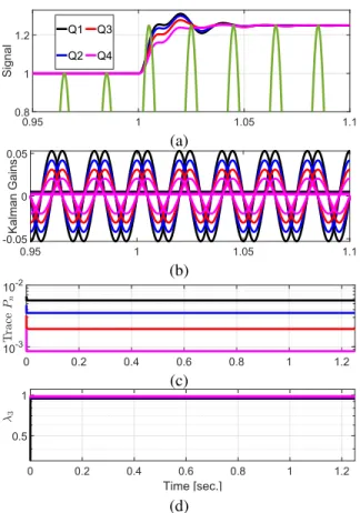
Figure 2. Numerical simulation results with four different process noise co-variance values Q ( , , , ): (a) grid voltage signal and estimated amplitudes, (b) Kalman gains, (c) trace of matrixP, and (d) third eigenvalues of matrix
˜
An. Q =αdiag([0.1 1 1]),α= 0.05,0.04,0.03, and0.02.
matrixPn,which relies on the process noise covariance matrix
Q, obtaining an analytical formula for the Kalman gain Kn
is difficult. To overcome this problem, numerical simulation can be useful. Numerical simulation results with four different values of Q are given in Fig. 2. Figure 2d shows that the third eigenvalues always remained less than 1. As a result, the stability of error system (10) can be established.
B. Extension to grid voltage with harmonics
In the presence of harmonics, the grid voltage can be modeled as: y=V0+ n X i=1 Visin(ωit+θi), (11)
whereiindicates theith component of the harmonic signal. In
this case, the extended states become:
x= [x1x2x3 . . . x2n x2n+1]T,
= [V0V1cos(θ1)V1sin(θ1) . . . Vncos(θn)Vnsin(θn)]T.
(12) By considering the extended statesxin eq. (12), the discrete-time model of the grid voltage can be written as:
process noise, E[wnwn] =Rn = r is the covariance of the
output noise, state matrix An =I2n+1 and the output matrix
is given by:
Cn= [1 sin(φ1) cos(φ1). . . sin(φn) cos(φn)],
where φi = ωinTs. Based on model (13), the Kalman filter
(4) and (5) can easily be applied. As this is straightforward, this extension had not been included.
III. RESULTS ANDDISCUSSIONS
This Section considers numerical simulation and experimen-tal results to demonstrate the suitability of the proposed KF-PLL given in Fig. 1. The covariance matrix for process and measurement noise for the proposed Kalman filter are selected as: Q=diag([0.005,0.05,0.05]) and R = 1. It can be seen that in the matrix Q, the first diagonal element belongs to the DC offset. It has already been suggested in [27] that the DC-offset estimation part should have slower dynamics than the other states. That is why the process noise covariance of DC offset is selected as ten times smaller than the other states. Initial value for the error covariance matrix and the initial value for the states are selected as: P0 = 1000I3 and
x0= [0; 0.5; 0]. These initialization parameters of the Kalman
filter are inspired by [39]. Finally, the frequency estimation parameter of the proposed technique has been selected as β= 50using trial and error method.
As comparison methods, we have selected two other ad-vanced techniques namely SOGI-PLL [25] and EPLL [40]. Both SOGI-PLL and EPLL in the original form are not capable to reject DC offset. Karimi-Ghartemaniet al. [27] suggested adding an additional integrator to estimate the DC offset for SOGI-PLL and EPLL. In this paper, we follow the same approach. Block diagrams of the considered SOGI-PLL and EPLL with DC offset rejection are given in figures 3 and 4. Parameters of SOGI part are selected as: k = √2 and kdc= 0.4 following the guidelines given in [27]. SOGI-PLL
works using the principle of Synchronous Reference Frame (SRF)-PLL (SRF-PLL). The parameters of SRF-PLL can be tuned as: kp = t4
s, ki =
k2
p
4ζ2, where ζ is the damping ratio
[41]. The same formula has been considered here with settling time ts = 0.06 and the damping ratio ζ = √12. Parameters
of EPLL are chosen following the guidelines given in [27] as: µ0 = 85, µ1 = µ3 = ωn and µ2 = 30000 where
ωn = 100π. All results presented in this Sec. are obtained
by considering 10KHz sampling frequency. The proposed technique is designed in discrete-time while SOGI-PLL and EPLL are designed in continuous-time. SOGI-PLL and EPLL are discretized using trapezoidal (i.e. Tustin) method. It is to be noted here that some of the existing implementations of KF-based grid synchronization techniques [10], [37] do not explicitly considers DC offset. As such comparison with
SOGI With DC Estimation
Figure 3. Block diagram of second-order generalized integrator phase locked-loop (SOGI-PLL) with DC offset rejection [27].
cos sin
Figure 4. Block diagram of enhanced phase locked-loop (EPLL) with DC offset rejection [27].
standard KF is avoided here for the purpose of fair comparison.
A. Simulation Results
To test the performance of the proposed KF-PLL, four chal-lenging test scenarios are considered for numerical simulation study. The test conditions are:
• S1: +2Hz jump in frequency. • S2: +45◦ jump in phase. • S3: −0.5p.u. jump in amplitude. • S4: +0.15p.u. jump in DC offset.
Numerical simulation results for S1 are given in Fig. 5. Fig. 5 shows the considered grid voltage signal, estimated frequencies and the instantaneous phase estimation errors for the three techniques. In the case of frequency estimation, proposed KF-PLL did not show any peak overshoot unlike the comparison techniques. In terms of settling time, both KF-PLL and EPLL converged in slightly higher than 2 cycles while SOGI-PLL took bit more time. The convergence time for KF-PLL is very competitive with respect to existing literature. It is to be mentioned here that all the techniques considered in this section provide DC offset rejection. The presence of DC offset rejection block slows down the dynamic response of grid synchronization techniques. In terms of instantaneous phase estimation errors, proposed KF-PLL and EPLL have similar peak overshoot, however, KF-PLL can be considered faster than EPLL. SOGI-PLL took more time to converge and the peak estimation error is two times bigger than the other two techniques. This test case demonstrated the fast frequency tracking capability of the proposed KF-PLL.
Phase angle jump is a challenging test condition for PLL-based grid synchronization techniques. Test scenario S2 con-siders +45◦ phase jump. Fig. 6 shows the considered grid voltage signal, estimated frequencies and the instantaneous phase estimation errors for the three techniques in case of S2.
-1 0 1
Voltage [p.u.]
Grid Voltage Signal
50 51 52 53 f [Hz] Estimated Frequencies KF-PLL EPLL SOGI-PLL 0.98 1 1.02 1.04 1.06 1.08 1.1 0 5
10 Phase Estimation Errors
KF-PLL EPLL SOGI-PLL
Figure 5. Comparative simulation results for S1:+2Hz jump in frequency.
-1 0 1
Voltage [p.u.]
Grid Voltage Signal
45 50 55 60 f [Hz] Estimated Frequencies KF-PLL EPLL SOGI-PLL 0.98 1 1.02 1.04 1.06 1.08 1.1 0 20 40
Phase Estimation Errors
KF-PLL EPLL SOGI-PLL
45 50 55 f [Hz] Estimated Frequencies KF-PLL EPLL SOGI-PLL 0.98 1 1.02 1.04 1.06 1.08 1.1 -20 -10 0 10 20
Phase Estimation Errors
KF-PLL EPLL SOGI-PLL
Figure 7. Comparative simulation results for S3:−0.5p.u. jump in amplitude.
-1 0 1
Voltage [p.u.]
Grid Voltage Signal
48 49 50 51 f [Hz] Estimated Frequencies KF-PLL EPLL SOGI-PLL 0.98 1 1.02 1.04 1.06 1.08 1.1 -5 0 5 10
Phase Estimation Errors
KF-PLL EPLL SOGI-PLL
Figure 8. Comparative simulation results for S4:+0.15p.u. jump in DC offset.
Fig. 6 demonstrates that KF-PLL is very quick to react in the presence of phase angle jump. Out of the three techniques, KF-PLL converged faster in ≈ 3 cycles with 50% smaller peak overshoot. Similarly, KF-PLL outperformed SOGI-PLL and EPLL in terms of phase estimation error. The error for KF-PLL, EPLL and SOGI-PLL converged in approximately 2.5,
3.5, and4.5 respectively. These results show that KF-PLL is very suitable even in challenging scenarios like sudden phase angle jump.
Nowadays, many grid codes require the renewable energy
1 1.05 1.1 1.15 1 1.05 1.1 1.15 40 45 50 55 60 f [Hz] Estimated Frequencies SOGI-PLL EPLL KF-PLL 0.99 1 1.01 1.02 1.03 1.04 1.05 1.06 Time [sec.] 40 45 50 55 60 f [Hz]
Estimated Frequencies (Zoomed View)
SOGI-PLL EPLL KF-PLL
Figure 9. Comparative simulation results for grid voltage signal with exponentially decaying harmonics.
sources to be connected to the grid despite large amplitude fault in the grid. This is known as low voltage ride through (LVRT) capability. This kind of situation is considered in test scenario S3. This test scenario considers large voltage sag of 0.5p.u. Fig. 7 shows the considered grid voltage signal, estimated frequencies and the instantaneous phase estimation errors for the three techniques in case of S3. As shown in Fig. 7, the frequency estimation for KF-PLL converged very fast in approximately2.5 cycles while SOGI-PLL and EPLL took significantly longer time to converge. Similar performance can be observed for phase estimation error as well. KF-PLL converged in approximately 2.5 cycles while the other two techniques took significantly longer time to converge. This test shows the suitability of the proposed alternative implementation of KF-PLL in the presence of large voltage sag.
Grid synchronization techniques generally sit inside the inverter controller block. Inverter controller depends on the sampled measurement of the grid voltage signal. This process may introduce DC offset in the measured voltage signal. Moreover, due to transformer saturation or various faults, DC offset may become unavoidable. Test case S4 considers sudden jump of+0.15p.u. in the DC offset. Fig. 8 shows the considered grid voltage signal, estimated frequencies and the instantaneous phase estimation errors for the three techniques in case of S4. As shown in Fig. 8, all the techniques converged in approximately3cycles. In case of frequency estimation, all the techniques also had similar peak overshoots. However, in the case of phase estimation error, SOGI-PLL had the lowest peak overshoot while EPLL and KF-PLL had higher peak overshoot than SOGI-PLL.
To demonstrate the robustness of the comparative tech-niques, the next test considers the presence of exponentially
0 10 20 30 40 50
SNR [dB]
100
NME (%)
EPLL KF-PLL SOGI-PLL
Figure 10. NME versus signal SNR forN= 104.
decaying harmonic signal in the grid voltage. The grid voltage signal in this case is given by:
y=V sin(ωt+θ) +e−t X
i=3,5,9
sin(iωt). (14) The exponentially decaying harmonic signal is activated at t = 1sec. Numerical simulation results in this case are given in Fig. 9, where the estimated frequencies show that all the techniques reacted very quickly to the change in grid voltage signal. However, the proposed KF-PLL outperformed EPLL and SOGI-PLL. The ripple magnitude of KF-PLL is roughly 50%smaller than EPLL. Zoomed view show that the peak overshoot of the proposed KF-PLL is also significantly smaller than EPLL and SOGI-PLL. These results show that the proposed KF-PLL has robust performance even in the presence of large amplitude exponentially decaying harmonic signal.
Tests S1-S4 are very useful to test the dynamic performance of the comparative techniques. However, these tests do not consider the effect of noise and/or sampling frequency. To analyze the effect of these factors, let us consider the following normalized mean error (NME) for the estimated frequency:
NME= 1 N N X i=1 |f(i)−fˆ(i)| |f(i)| , (15) where N is the signal length. Ideal value of NME is 0. In practice, this value is not achievable due to the effect of noise. So, NME can be a suitable indicator to determine the noise sensitivity of the comparative techniques. NME values for different signal-to-noise ratio (SNR) are given in Fig. 10. Out of the three techniques, the proposed KF-PLL has a significantly lower NME than EPLL and SOGI-PLL. Unlike EPLL and SOGI-PLL, Kalman filter systemically considers the effect of noise through process and measurement covariance matrices. This helps to achieve superior performance with respect to Gaussian noise present in the measured grid voltage signal.
In this work, the sampling frequency is considered to be
10kHz. This implies to200samples per cycle in the nominal frequency case. This sampling frequency can be high for low-cost micro-controller based implementation. In order to test the effect of sampling frequency on NME, the next test considers the number of samples per cycle between 100 and 200. This corresponds to a sampling frequency between5kHz and 10kHz. Simulation results in this case for a SNR of
37dB are given in Fig. 11. This test also shows the superiority
100 120 140 160 180 200 Samples/Cycle 0.03 0.04 0.05 0.06 0.07 NME (%) EPLL KF-PLL SOGI-PLL
Figure 11. NME versus samples/cycle for SNR =37dB.
Figure 12. Overview of the experimental setup.
of the proposed Kalman filter PLL. The proposed technique is designed in discrete-time whereas SOGI-PLL and EPLL are designed in continuous-time. So, discretization of the continuous integrators are necessary to implement SOGI-PLL and EPLL. It is well known that sampling frequency does have an effect on the discretization of continuous systems. In-creasing the sampling frequency can improve the discretization accuracy. So, EPLL and SOGI-PLL are more sensitive to low sampling frequency than KF-PLL.
From all the simulation results presented in this Section, it can be seen that proposed KF-PLL performed very competi-tively with respect to other state-of-the-art techniques. In most cases, KF-PLL outperformed the other two techniques. These demonstrated the suitability of the proposed KF-PLL.
B. Experimental Results
The experimental setup used in this work is given in Fig. 12. The signal processing platform is designed using a Digital Signal Processor (DSP) TMS320F28379D and as-sociated measurement circuit. A LEM LV25-P sensor with associated offset circuit is used to measure the voltage at the point of common coupling. Comparative techniques are implemented in Matlab/Simulink and loaded into the DSP through Matlab/Simulink 2017b and C2000 Code Generation Tools v6.0.0 software. Autotransformer is used to generate voltage sag at the source side from the grid voltage. Harmonic distortion is generated by using nonlinear load. Grid frequency can not be changed. So, the change in frequency is obtained by
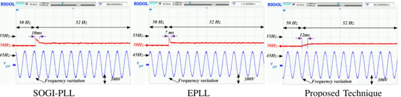
SOGI-PLL EPLL Proposed Technique Figure 13. Frequency estimation performance for scenario S1:+2Hz frequency jump
SOGI-PLL EPLL Proposed Technique
Figure 14. Frequency estimation performance for scenario S3:−0.5p.u. voltage sag.
SOGI-PLL EPLL Proposed Technique
Figure 15. Frequency estimation performance: from ideal to distorted grid.
using a synchronous generator where the speed of the machine is controlled to obtain the frequency variations.
For the experimental validation, we have considered simu-lation test scenario S1 and S3 (i.e. frequency and amplitude jump). Experimental results for the test scenario S1: +2Hz frequency jump is given in Fig. 13. Experimental results show that all the technique quickly reacted to the change in frequency. Similar to simulation study, both EPLL and SOGI-PLL showed peak overshoot while the proposed KF-PLL estimated the frequency without any overshoot. Moreover, the proposed technique converged considerably faster than the comparative techniques.
Test scenario S3 considers −0.5p.u. voltage sag. This is a challenging test condition. Experimental validation results for this test scenario are given in Fig. 14. Due to the way the test was realized, this grid voltage amplitude and phase both jumped simultaneously for SOGI-PLL and the proposed technique. However, for EPLL, the voltage sag coincided with the zero-crossing. Experimental results as given in Fig. 14 show that the proposed KF-PLL converged with lower peak overshoot than SOGI-PLL. EPLL has very noisy response
compared to SOGI-PLL and the proposed technique. It is to be noted here that in simulation, it is very easy to realize voltage sag with zero-crossing, however, this is difficult to realize in practice. As such, convergence time comparison between the techniques may not be fair in this case.
Test scenario S1 and S3 consider ideal grid without any distortion. However, due to the ever increasing presence of nonlinear loads, harmonics may not be avoided in the grid. To test the performance of the grid, the next test consider sudden addition of harmonics to the grid. Initially the grid has a Total Harmonic Distortion (THD) of only 0.8%. Suddenly the grid THD increased to18%. Experimental results for the ideal to distorted grid case are given in Fig. 15. None of the techniques explicitly consider harmonics. As such estimation ripple is unavoidable. However, proposed KF-PLL has the lowest ripple magnitude. The ripple in this case is bounded between 49.8Hz and 50.2Hz whereas the ripple magnitude between49.6Hz and50.4Hz and49.5Hz and51Hz for SOGI-PLL and ESOGI-PLL, respectively. These results demonstrate the harmonic robustness of the proposed KF-PLL in addition to fast convergence.
IV. CONCLUSION
Phase and frequency estimation of single-phase grid voltage signal has been studied in this paper. First a linear parametric model of the grid voltage signal has been developed using trigonometric manipulation. Then using the linear parametric model, linear Kalman filter has been applied for state es-timation. From the estimated states, the initial phase angle can be estimated. Following phase-based frequency estimation concept, the initial phase angle is used to estimate the unknown grid frequency. An advantage of the proposed alternative implementation of the linear Kalman filter is that it directly estimates the phase angle not the instantaneous phase. As such it can be considered as less sensitive to phase angle jump unlike PLL. Compared to PLL-based LKF, it has one less parameter to tune and simple frequency estimation loop. Comparative experimental results are provided with respect to SOGI-PLL and EPLL. Comparative experimental results demonstrated the suitability of the proposed technique. Exten-sion of the proposed technique to three-phase unbalanced grid will be considered in a future work.
REFERENCES
[1] M. A. Soliman, H. M. Hasanien, H. Z. Azazi, E. E. El-Kholy, and S. A. Mahmoud, “An adaptive fuzzy logic control strategy for performance enhancement of a grid-connected PMSG-based wind turbine,” IEEE Trans. Ind. Informat., vol. 15, no. 6, pp. 3163–3173, June 2019. [2] M. Merai, M. W. Naouar, I. Slama-Belkhodja, and E. Monmasson, “An
adaptive PI controller design for DC-link voltage control of single-phase grid-connected converters,”IEEE Trans. Ind. Electron., vol. 66, no. 8, pp. 6241–6249, 2018.
[3] O. Kukrer, S. Bayhan, and H. Komurcugil, “Model-based current control strategy with virtual time constant for improved dynamic response of three-phase grid-connected VSI,”IEEE Trans. Ind. Electron., vol. 66, no. 6, pp. 4156–4165, 2018.
[4] I. Sefa, S. Ozdemir, H. Komurcugil, and N. Altin, “An enhanced lyapunov-function based control scheme for three-phase grid-tied vsi with lcl filter,”IEEE Trans. Sustain. Energy, vol. 10, no. 2, pp. 504– 513, 2018.
[5] A. Rahoui, A. Bechouche, H. Seddiki, and D. O. Abdeslam, “Grid voltages estimation for three-phase PWM rectifiers control without AC voltage sensors,”IEEE Trans. Power Electron., vol. 33, no. 1, pp. 859– 875, 2017.
[6] M. C. Kisacikoglu, M. Kesler, and L. M. Tolbert, “Single-phase on-board bidirectional PEV charger for V2G reactive power operation,”
IEEE Trans. Smart Grid, vol. 6, no. 2, pp. 767–775, 2014.
[7] S. Biricik, H. Komurcugil, N. D. Tuyen, and M. Basu, “Protection of sensitive loads using sliding mode controlled three-phase DVR with adaptive notch filter,”IEEE Trans. Ind. Electron., vol. 66, no. 7, pp. 5465–5475, 2018.
[8] S. Murugesan and V. Murali, “Hybrid analyzing technique based active islanding detection for multiple dgs,”IEEE Trans. Ind. Informat., vol. 15, no. 3, pp. 1311–1320, March 2019.
[9] B. P. McGrath, D. G. Holmes, and J. J. H. Galloway, “Power converter line synchronization using a discrete fourier transform (DFT) based on a variable sample rate,”IEEE Trans. Power Electron., vol. 20, no. 4, pp. 877–884, 2005.
[10] Y. Amirat, Z. Oubrahim, H. Ahmed, M. Benbouzid, and T. Wang, “Phasor estimation for grid power monitoring: Least square vs linear Kalman filter,”Energies, vol. 13, no. 10, p. 2456, 2020.
[11] Y. Terriche, J. M. Guerrero, and J. C. Vasquez, “Performance im-provement of shunt active power filter based on non-linear least-square approach,”Electr. Power Syst. Res., vol. 160, pp. 44–55, 2018. [12] V. Choqueuse, A. Belouchrani, F. Auger, and M. Benbouzid, “Frequency
and phasor estimations in three-phase systems: Maximum likelihood algorithms and theoretical performance,” IEEE Trans. Smart Grid, vol. 10, no. 3, pp. 3248–3258, 2018.
[13] V. Choqueuse, P. Granjon, A. Belouchrani, F. Auger, and M. Benbouzid, “Monitoring of three-phase signals based on singular-value decomposi-tion,”IEEE Trans. Smart Grid, 2019.
[14] R. Teodorescu, M. Liserre, and P. Rodriguez, Grid converters for photovoltaic and wind power systems. John Wiley & Sons, 2011, vol. 29.
[15] H. Ahmed, M. Bierhoff, and M. Benbouzid, “Multiple nonlinear har-monic oscillator-based frequency estimation for distorted grid voltage,”
IEEE Trans. Instrum. Meas., vol. 69, no. 6, pp. 2817 – 2825, 2020. [16] A. Kherbachi, A. Chouder, A. Bendib, K. Kara, and S. Barkat,
“Enhanced structure of second-order generalized integrator frequency-locked loop suitable for DC-offset rejection in single-phase systems,”
Electr. Power Syst. Res., vol. 170, pp. 348–357, 2019.
[17] S. Mekhilef, M. Tarek, and N. Abd. Rahim, “Single-phase hybrid active power filter with adaptive notch filter for harmonic current estimation,”
IETE Journal of Research, vol. 57, no. 1, pp. 20–28, 2011.
[18] I. Kamwa, M. Leclerc, and D. McNabb, “Performance of demodulation-based frequency measurement algorithms used in typical PMUs,”IEEE Trans. Power Del., vol. 19, no. 2, pp. 505–514, 2004.
[19] H. Ahmed and M. Benbouzid, “Demodulation type single-phase PLL with DC offset rejection,”Electron. Lett., vol. 56, no. 7, pp. 344–347, 2020.
[20] A. Safa, E. M. Berkouk, Y. Messlem, Z. Chedjara, and A. Gouichiche, “A pseudo open loop synchronization technique for heavily distorted grid voltage,”Electr. Power Syst. Res., vol. 158, pp. 136–146, 2018. [21] S. Golestan, A. Vidal, A. G. Yepes, J. M. Guerrero, J. C. Vasquez, and
J. Doval-Gandoy, “A true open-loop synchronization technique,”IEEE Trans. Ind. Informat., vol. 12, no. 3, pp. 1093–1103, 2016.
[22] X. Quan, X. Dou, Z. Wu, M. Hu, and A. Q. Huang, “Complex-coefficient complex-variable filter for grid synchronization based on linear quadratic regulation,”IEEE Trans. Ind. Informat., vol. 14, no. 5, pp. 1824–1834, 2017.
[23] Y. Terriche, M. U. Mutarraf, M. Mehrzadi, A. Lashab, J. M. Guerrero, J. C. Vasquez, and D. Kerdoun, “Adaptive CDSC-based open-loop synchronization technique for dynamic response enhancement of active power filters,”IEEE Access, vol. 7, pp. 96 743–96 752, 2019. [24] M. E. Meral and D. Çelik, “Benchmarking simulation and theory of
various PLLs produce orthogonal signals under abnormal electric grid conditions,” Electrical Engineering, vol. 100, no. 3, pp. 1805–1817, 2018.
[25] M. Ciobotaru, R. Teodorescu, and F. Blaabjerg, “A new single-phase PLL structure based on second order generalized integrator,” in 2006 37th IEEE Power Electronics Specialists Conference. IEEE, 2006, pp. 1–6.
[26] M. H. Bierhoff, “A general PLL-type algorithm for speed sensorless control of electrical drives,”IEEE Trans. Ind. Electron., vol. 64, no. 12, pp. 9253–9260, 2017.
[27] M. Karimi-Ghartemani, S. A. Khajehoddin, P. K. Jain, A. Bakhshai, and M. Mojiri, “Addressing DC component in PLL and notch filter algorithms,”IEEE Trans. Power Electron., vol. 27, no. 1, pp. 78–86, 2011.
[28] A. Bechouche, H. Sediki, D. O. Abdeslam, and S. Haddad, “An adaptive neural PLL for grid synchronization,” in IECON 2012-38th Annual Conference on IEEE Industrial Electronics Society. IEEE, 2012, pp. 4451–4456.
[29] Z. Chedjara, A. Massoum, S. Massoum, P. Wira, A. Safa, and A. Gouichiche, “A novel robust PLL algorithm applied to the control of a shunt active power filter using a self tuning filter concept,” in 2018 IEEE International Conference on Industrial Technology (ICIT). IEEE, 2018, pp. 1124–1131.
[30] A. Bendib, A. Chouder, K. Kara, A. Kherbachi, S. Barkat, and W. Issa, “New modeling approach of secondary control layer for autonomous single-phase microgrids,”J. Franklin Inst., vol. 356, no. 13, pp. 6842– 6874, 2019.
[31] T. Ngo, Q. Nguyen, and S. Santoso, “Improving performance of single-phase SOGI-FLL under DC-offset voltage condition,” inIECON 2014-40th Annual Conference of the IEEE Industrial Electronics Society. IEEE, 2014, pp. 1537–1541.
[32] H. Ahmed, S.-A. Amamra, and M. Bierhoff, “Frequency-locked loop-based estimation of single-phase grid voltage parameters,”IEEE Trans. Ind. Electron., vol. 66, no. 11, pp. 8856–8859, 2019.
[33] M. L. Pay and H. Ahmed, “Modeling and tuning of circular limit cycle oscillator FLL with pre-loop filter,”IEEE Trans. Ind. Electron., vol. 66, no. 12, pp. 9632–9635, 2019.
[34] H. Ahmed, S.-A. Amamra, and I. Salgado, “Fast estimation of phase and frequency for single-phase grid signal,”IEEE Trans. Ind. Electron., vol. 66, no. 8, pp. 6408–6411, 2019.
[35] B. Singh, F. Chishti, and S. Murshid, “Disturbance rejection through adaptive frequency estimation observer for wind-solar integrated ac
loop with Kalman estimator-based filter for single-phase applications,” inIECON 2006. IEEE, 2006, pp. 525–530.
[38] R. Grover and P. Y. Hwang, “Introduction to random signals and applied Kalman filtering,”Willey, New York, 1992.
[39] C.-H. Huang, C.-H. Lee, K.-J. Shih, and Y.-J. Wang, “A robust technique for frequency estimation of distorted signals in power systems,”IEEE Trans. Instrum. Meas., vol. 59, no. 8, pp. 2026–2036, 2010.
[40] M. Karimi-Ghartemani, Enhanced phase-locked loop structures for power and energy applications. John Wiley & Sons, 2014.
[41] S. Golestan and J. M. Guerrero, “Conventional synchronous reference frame phase-locked loop is an adaptive complex filter,”IEEE Trans. Ind. Electron., vol. 62, no. 3, pp. 1679–1682, 2015.
APPENDIX
Consider the grid voltage model (1) without the DC offset: y=Vsin(ωt+θ
| {z }
Φ
), (16)
By considering x = [x1 x2]T = [V cos(Φ) Vsin(Φ)]T, the
grid voltage dynamics in state-space form can be written as:
˙ x= 0 −ω ω 0 | {z } A x, (17a) y= 0 1 | {z } C x. (17b)
Model (17) is developed in continuous-time. By considering t=nTs,model (17) can be exactly discretized by calculating
An=eAnTs= cos(ωnT s) −sin(ωnTs) sin(ωnTs) cos(ωnT s) , (18) Cn=C. (19)
Then model (3) can be used to describe the dynamics of system (17) in discrete-time where the discrete-time state and output matrices are given by eq. (18) and (19). Moreover, the process noise covariance is given byQ=qI2. Everything else remains
the same as given in Sec. II. Then, the implementation of Kalman filter is straightforward and require eq. (4) and (5).
Kalman filter (4)-(5) requires the estimated frequency ω.ˆ
For this purpose, an additional frequency estimation part is required. This frequency estimation part can be designed using the principle of PLL or FLL. For the sake of simplicity, here we consider FLL-based approach. In this approach, the frequency estimation dynamics is given by:
˙ˆ ω=− βexˆ1 ˆ x2 1+ ˆx22 , (20)
where β > 0 is the FLL gain. The continuous integrator in eq. (20) can be discretized using various techniques to be compatible with discrete-time implementation of the Kalman filter. Moreover, from the estimated states, the phaseΦcan be estimated as:
Hafiz Ahmed (S’10--M’17--SM’20) received the
Ph.D. degree in Automatic Control from the Uni-versity of Lille 1, France, in 2016. He received the EECI (European Embedded Control Institute) Ph.D. award in 2017 and the Best PhD Theses award from the Research Cluster on Modeling, Analysis and Management of Dynamic Systems (GDR-MACS) of the National Council of Scientific Research (CNRS) in France in 2017.
From 2016 to 2020, he was with Clemson Uni-versity, USA, Asia Pacific UniUni-versity, Bangladesh, North South University, Bangladesh, and Coventry University, UK. Since 2020, he has been with Birmingham City University, UK. He is interested in applied control engineering with special focus in energy and environment. He is an Associate Editor of the INTERNATIONAL JOURNAL OF ELEC-TRICAL ENGINEERING & EDUCATION.
Samet Biricik (M’12--SM’19) received the B.Sc.,
M.Sc., and Ph.D. degrees in electrical and electronic engineering from the Near East University, Nicosia, Mersin 10, Turkey, in 2006, 2009, and 2013, respec-tively. He is currently a lecturer in the European University of Lefke, Lefke and a Research Fellow in the School of Electrical and Electronic Engi-neering of Technological University Dublin, Dublin, Ireland. His research interests include the applica-tion of power electronics, power quality, electrical machines, and high-voltage engineering.
Mohamed Benbouzid (S’92--M’95--SM’98--F’20)
received the B.Sc. degree in electrical engineering from the University of Batna, Batna, Algeria, in 1990, the M.Sc. and Ph.D. degrees in electrical and computer engineering from the National Polytechnic Institute of Grenoble, Grenoble, France, in 1991 and 1994, respectively, and the Habilitationa`Diriger des Recherches degree from the University of Picardie “Jules Verne, ”Amiens, France, in 2000.
After receiving the Ph.D. degree, he joined the Pro-fessional Institute of Amiens, University of Picardie “Jules Verne, ”where he was an Associate Professor of electrical and computer engineering. Since September 2004, he has been with the University of Brest, Brest, France, where he is a Full Professor of electrical engineering. Prof. Benbouzid is also a Distinguished Professor and a 1000 Talent Expert at the Shanghai Maritime University, Shanghai, China. His main research interests and experience include analysis, design, and control of electric machines, variable-speed drives for traction, propulsion, and renewable energy applications, and fault diagnosis of electric machines.
Prof. Benbouzid has been elevated as an IEEE Fellow for his contributions to diagnosis and fault-tolerant control of electric machines and drives. He is also a Fellow of the IET. He is the Editor-in-Chief of the INTERNATIONAL JOURNAL ON ENERGY CONVERSION and the APPLIED SCIENCES (MDPI) Section on Electrical, Electronics and Communications Engineering. He is a Subject Editor for the IET RENEWABLE POWER GENERA-TION. He is also an Associate Editor of the IEEE TRANSACTIONS ON ENERGY CONVERSION.
![Figure 4. Block diagram of enhanced phase locked-loop (EPLL) with DC offset rejection [27].](https://thumb-us.123doks.com/thumbv2/123dok_us/1441733.2693062/5.918.494.817.124.516/figure-block-diagram-enhanced-phase-locked-offset-rejection.webp)