3.5"-SBC-APL
Doc. User Guide Rev. 1.1 Doc. ID: 1061-0789
3.5"-SBC-APL - USER GUIDE
Disclaimer
Kontron would like to point out that the information contained in this user guide may be subject to alteration, particularly as a result of the constant upgrading of Kontron products. This document does not entail any guarantee on the part of Kontron with respect to technical processes described in the user guide or any product characteristics set out in the user guide. Kontron assumes no responsibility or liability for the use of the described product(s), conveys no license or title under any patent, copyright or mask work rights to these products and makes no representations or warranties that these products are free from patent, copyright or mask work right infringement unless otherwise specified. Applications that are described in this user guide are for illustration purposes only. Kontron makes no representation or warranty that such application will be suitable for the specified use without further testing or modification. Kontron expressly informs the user that this user guide only contains a general description of processes and instructions which may not be applicable in every individual case. In cases of doubt, please contact Kontron.
This user guide is protected by copyright. All rights are reserved by Kontron. No part of this document may be reproduced, transmitted, transcribed, stored in a retrieval system, or translated into any language or computer language, in any form or by any means (electronic, mechanical, photocopying, recording, or otherwise), without the express written permission of Kontron. Kontron points out that the information contained in this user guide is constantly being updated in line with the technical alterations and improvements made by Kontron to the products and thus this user guide only reflects the technical status of the products by Kontron at the time of publishing. Brand and product names are trademarks or registered trademarks of their respective owners.
© 2018 by Kontron S&T AG Kontron S&T AG Lise-Meitner-Str. 3-5 86156 Augsburg Germany www.kontron.com
High Risk Applications Hazard Notice
THIS DEVICE AND ASSOCIATED SOFTWARE ARE NOT DESIGNED, MANUFACTURED OR INTENDED FOR USE OR RESALE FOR THE OPERATION OF NUCLEAR FACILITIES, THE NAVIGATION, CONTROL OR
COMMUNICATION SYSTEMS FOR AIRCRAFT OR OTHER TRANSPORTATION, AIR TRAFFIC CONTROL, LIFE SUPPORT OR LIFE SUSTAINING APPLICATIONS, WEAPONS SYSTEMS, OR ANY OTHER APPLICATION IN A HAZARDOUS ENVIRONMENT, OR REQUIRING FAIL-SAFE PERFORMANCE, OR IN WHICH THE FAILURE OF PRODUCTS COULD LEAD DIRECTLY TO DEATH, PERSONAL INJURY, OR SEVERE PHYSICAL OR
ENVIRONMENTAL DAMAGE (COLLECTIVELY, "HIGH RISK APPLICATIONS").
You understand and agree that your use of Kontron devices as a component in High Risk Applications is entirely at your risk. To minimize the risks associated with your products and applications, you should provide adequate design and operating safeguards. You are solely responsible for compliance with all legal, regulatory, safety, and security related requirements concerning your products. You are responsible to ensure that your systems (and any Kontron hardware or software components incorporated in your systems) meet all applicable requirements. Unless otherwise stated in the product documentation, the Kontron device is not provided with error-tolerance capabilities and cannot therefore be deemed as being engineered, manufactured or setup to be compliant for implementation or for resale as device in High Risk Applications. All application and safety related information in this document (including application descriptions, suggested safety measures, suggested Kontron products, and other materials) is provided for reference only.
Revision History
Revision Brief Description of Changes Date of Issue Author
1.0 Basic issue 2018-Mar-07 hjs
1.1 Corrected COM1, COM2 and USB1 2018-Oct-26 CW
Terms and Conditions
Kontron warrants products in accordance with defined regional warranty periods. For more information about warranty compliance and conformity, and the warranty period in your region, visit http://www.kontron.com/terms-and-conditions.
Kontron sells products worldwide and declares regional General Terms & Conditions of Sale, and Purchase Order Terms & Conditions. Visit http://www.kontron.com/terms-and-conditions.
For contact information, refer to the corporate offices contact information on the last page of this user guide or visit our website CONTACT US.
Customer Support
Find Kontron contacts by visiting: http://www.kontron.com/support.
Customer Service
As a trusted technology innovator and global solutions provider, Kontron extends its embedded market strengths into a services portfolio allowing companies to break the barriers of traditional product lifecycles. Proven product expertise coupled with collaborative and highly-experienced support enables Kontron to provide exceptional peace of mind to build and maintain successful products.
For more details on Kontron’s service offerings such as: enhanced repair services, extended warranty, Kontron training academy, and more visithttp://www.kontron.com/support-and-services/services.
Customer Comments
If you have any difficulties using this user guide, discover an error, or just want to provide some feedback, contact Kontron support. Detail any errors you find. We will correct the errors or problems as soon as possible and post the revised user guide on our website.
Symbols
The following symbols may be used in this user guide
DANGER indicates a hazardous situation which, if not avoided, will result in death or serious injury.
WARNING indicates a hazardous situation which, if not avoided, could result in death or serious injury.
CAUTION indicates a hazardous situation which, if not avoided, may result in minor or moderate injury.
NOTICE indicates a property damage message.
Electric Shock!
This symbol and title warn of hazards due to electrical shocks (> 60 V) when touching
products or parts of products. Failure to observe the precautions indicated and/or prescribed by the law may endanger your life/health and/or result in damage to your material.
ESD Sensitive Device!
This symbol and title inform that the electronic boards and their components are sensitive to static electricity. Care must therefore be taken during all handling operations and inspections of this product in order to ensure product integrity at all times.
HOT Surface!
Do NOT touch! Allow to cool before servicing.
Laser!
This symbol inform of the risk of exposure to laser beam from an electrical device. Eye protection per manufacturer notice shall review before servicing.
This symbol indicates general information about the product and the user guide. This symbol also indicates detail information about the specific product configuration.
For Your Safety
Your new Kontron product was developed and tested carefully to provide all features necessary to ensure its compliance with electrical safety requirements. It was also designed for a long fault-free life. However, the life expectancy of your product can be drastically reduced by improper treatment during unpacking and installation. Therefore, in the interest of your own safety and of the correct operation of your new Kontron product, you are requested to conform with the following guidelines.
High Voltage Safety Instructions
As a precaution and in case of danger, the power connector must be easily accessible. The power connector is the product’s main disconnect device.
Warning
All operations on this product must be carried out by sufficiently skilled personnel only.
Electric Shock!
Before installing a non hot-swappable Kontron product into a system always ensure that your mains power is switched off. This also applies to the installation of piggybacks. Serious electrical shock hazards can exist during all installation, repair, and maintenance operations on this product. Therefore, always unplug the power cable and any other cables which provide external voltages before performing any work on this product.
Earth ground connection to vehicle’s chassis or a central grounding point shall remain connected. The earth ground cable shall be the last cable to be disconnected or the first cable to be connected when performing installation or removal procedures on this product.
Special Handling and Unpacking Instruction
ESD Sensitive Device!
Electronic boards and their components are sensitive to static electricity. Therefore, care must be taken during all handling operations and inspections of this product, in order to ensure product integrity at all times.
Do not handle this product out of its protective enclosure while it is not used for operational purposes unless it is otherwise protected.
Whenever possible, unpack or pack this product only at EOS/ESD safe work stations. Where a safe work station is not guaranteed, it is important for the user to be electrically discharged before touching the product with his/her hands or tools. This is most easily done by touching a metal part of your system housing.
It is particularly important to observe standard anti-static precautions when changing piggybacks, ROM devices, jumper settings etc. If the product contains batteries for RTC or memory backup, ensure that the product is not placed on conductive surfaces, including anti-static plastics or sponges. They can cause short circuits and damage the batteries or conductive circuits on the product.
General Instructions on Usage
In order to maintain Kontron’s product warranty, this product must not be altered or modified in any way. Changes or modifications to the product, that are not explicitly approved by Kontron and described in this user guide or received from Kontron’s Technical Support as a special handling instruction, will void your warranty.
This product should only be installed in or connected to systems that fulfill all necessary technical and specific environmental requirements. This also applies to the operational temperature range of the specific board version, that must not be exceeded. If batteries are present, their temperature restrictions must be taken into account. In performing all necessary installation and application operations, only follow the instructions supplied by the present User Guide.
Keep all the original packaging material for future storage or warranty shipments. If it is necessary to store or ship the product then re-pack it in the same manner as it was delivered.
Special care is necessary when handling or unpacking the product. See Special Handling and Unpacking Instruction.
Environmental Protection Statement
This product has been manufactured to satisfy environmental protection requirements where possible. Many of the components used (structural parts, printed circuit boards, connectors, batteries, etc.) are capable of being recycled. Final disposition of this product after its service life must be accomplished in accordance with applicable country, state, or local laws or regulations.
Environmental protection is a high priority with Kontron. Kontron follows the WEEE directive
You are encouraged to return our products for proper disposal.
The Waste Electrical and Electronic Equipment (WEEE) Directive aims to:
Reduce waste arising from electrical and electronic equipment (EEE)
Make producers of EEE responsible for the environmental impact of their products, especially when the product become waste
Encourage separate collection and subsequent treatment, reuse, recovery, recycling and sound environmental disposal of EEE
Improve the environmental performance of all those involved during the lifecycle of EEE
Special care is necessary when handling or unpacking the product. See Special Handling and Unpacking Instruction.
Lithium Battery Precautions
If your product is equipped with a lithium battery, take the following precautions when replacing the battery.
Danger of explosion if the lithium battery is incorrectly replaced.
• Replace only with the same or equivalent type recommended by the manufacturer • Dispose of used batteries according to the manufacturer’s instructions
Table of Contents
Symbols ... 6
For Your Safety ... 7
High Voltage Safety Instructions ... 7
Special Handling and Unpacking Instruction ... 7
General Instructions on Usage... 8
Environmental Protection Statement ... 8
Table of Contents ... 9
List of Tables ... 10
List of Figures ... 10
1/ Introduction ... 11
2/ Installation Procedures ... 12
2.1. Installing the Board ... 12
2.2. Chassis Safety Standards ... 13
3/ Product Variants ... 14
4/ Product Specification ... 15
4.1. Component Data... 15
4.2. Standards and Certificates ... 17
4.3. Block Diagram ... 18
4.4. Supported Processors ... 19
4.4.1. Processor Cooling ... 19
4.5. System Memory Support ... 20
4.6. Graphics ... 20
4.7. Power Consumption ... 20
5/ Mainboard views ... 22
5.1. Top Side ... 22
5.2. External I/O Connector Side ... 23
5.3. Rear Side ... 24
6/ I/O Connectors ... 25
6.1. USB Connectors ... 25
6.2. Ethernet Connectors ... 26
6.3. Serial Port Connector (COM1) ... 26
6.4. Display Port Connector ... 27
6.5. HDMI Connector ... 28
7/ Internal Connectors ... 29
7.1. USB Connectors ... 29
7.2. LVDS Connector ... 29
7.3. Internal Serial Port (COM2) ... 31
7.4. SATA Connector (SATA) ... 31
7.5. SATA Internal Power(SATA_PWR1) ... 32
7.6. Audio Connector (AUDIO1) ... 32
7.7. Buzzer Connector (BZ1) ... 33
7.8. Front Panel (FP1)... 33
7.9. System Fan Connector (SYS_FAN1) ... 33
7.10. Power Connector (J1) ... 34
7.11. Mini PCIe Card socket 1 (MPCIE1/2) ... 34
7.12. CMOS Internal (CMOS1/2) ... 35
8.1. Setup Menus ... 37
8.2. Main Setup Menu... 37
8.3. Advanced Setup Menu ... 37
8.4. Chipset Setup Menu ... 42
8.5. Security Setup Menu ... 45
8.6. Boot Setup Menu ... 45
8.7. Save & Exit Setup Menu ... 46
Appendix: List of Acronyms ... 47
List of Tables
Table 1: Standard operating temperature (0°C to +60°C) ... 14Table 2: Industrial Temperature (-40°C to +85°C) ... 14
Table 3: Component Data ... 15
Table 4: Standards and Certifications ... 17
Table 5: Specification of Processor Variants ... 19
Table 6: On-Board Graphics Output ... 20
Table 7: Supply Voltage Requirements ... 21
Table 8: Main Setup Menu Sub-Screens Functions ... 37
Table 9: Advanced Setup Menu Sub-Screens and Functions ... 37
Table 10: Chipset Setup Menu Functions ... 42
Table 11: Security Setup Menu Functions ... 45
Table 12: Boot Priority Order ... 45
Table 13: Save & Exit Setup Menu Functions ... 46
Table 14: List of Acronyms ... 47
List of Figures
Figure 1: System Block Diagram... 18Figure 2: 3.5-SBC-APL with CPU Cooler ... 19
Figure 3: Top Side View ... 22
Figure 4: I/O Connector Panel View ... 23
Figure 5: Rear Side Board View ... 24
Figure 6: Dual stack USB 3.0 Connector ... 25
Figure 7: Ethernet LAN Connector (RJ45 Female) ... 26
Figure 8: Serial Connector ... 26
Figure 9: Display Port Connector ... 27
Figure 10: HDMI Graphics Connector ... 28
Figure 11: USB 2.0 Connector (USB1) ... 29
Figure 12: LVDS 40-Pin Connector ... 29
Figure 13: Serial Port Connector (COM2) ... 31
Figure 14: SATA Connector ... 31
Figure 15: SATA Power Internal Connector ... 32
Figure 16: Audio Connector ... 32
Figure 17: Buzzer connector (BZ1) ... 33
Figure 18: Front Panel Connector ... 33
Figure 19: System Fan Connector ... 33
Figure 20: Internal Power Connector (J1) ... 34
Figure 21: 52-pin Mini PCIe Card ... 34
1/
Introduction
This user guide describes the 3.5-SBC-APL motherboard from Kontron named as 3.5-SBC-APL within this user guide. The 3.5-SBC-APL is a 3.5” form factor, single board computer based on the Intel® Apollo Lake processor and features:
Intel® Atom™ Mobile processor family with (2 MB Cache, from 2 GHz to 1.8 GHz), Apollo SoC (System-on-Chip)
Intel® Mobile Celeron®N3350 processor with (2 MB cache, at 2.4 GHz) , TDP 6 W
System memory up to 8 GB maximum
1x DDR3L SO-DIMM (1.35 V, 1867 MHz) non ECC memory
3x independent graphic displays: 1x DP, 1x HDMI and 1x LVDS
2x 10BASE-T/100BASE-TX/1000BASE-T Mbit Ethernet (IEEE802.3 conformity)
2x USB 3.0 on the external I/O connector panel and 1 x USB3.0 on the internal header
1x USB 2.0 and 1x USB3.0 on the front panel internal header
1x RS232/RS422/RS485 and 1 x RS232(internal)
TPM2.0 and WIBU security features
2x PCIe mini
Use of this users guide implies a basic knowledge of PC-AT hardware and software. This user guide is focussed on describing the 3.5-SBC-APL motherboard’s special features and is not intended to be a standard PC-AT textbook. The configuration and setup of the CPU board is either carried out automatically or manually by the user via the BIOS setup menus.
Before switching on the power, new users are recommended to study the short installation procedure in the following chapter Installation Procedures.
For the latest revision of this user guide, datasheet, thermal simulations, BIOS, drivers, BSP’s (Board Support Packages), Mechanical drawings (2D and 3D), visit http://www.kontron.com/.
2/
Installation Procedures
2.1.
Installing the Board
ESD Sensitive Device
Electrostatic discharge (ESD) can damage equipment and impair electrical circuitry.
• Wear ESD-protective clothing and shoes
• Wear an ESD-preventive wrist strap attached to a good earth ground
• Check the resistance value of the wrist strap periodically (OK: 1 MΩ to 10 MΩ)
• Transport and store the board in an antistatic bag
• Handle the board only at an approved ESD workstation
• Handle the board only by the edges
To get the board running follow the steps listed below. If the board shipped by KONTRON already has components such as a RAM and CPU cooler mounted, then skip the relevant step(s).
1. Turn off the PSU (Power Supply Unit)
Turn off PSU (Power Supply Unit) completely (no mains power connected to the PSU) or leave the Power Connectors unconnected while configuring the board. Otherwise components (RAM, LAN cards etc.) might get damaged. Make sure to use a standard ATX PSU with a suitable cable kit and PS_ON# active.
2. Insert the memory module(s)
Be careful to push the memory module in the slot(s) before locking the tabs. 3. Cooler Installation
The 3.5-SBC-APL comes with a pre-installed cooler. 4. Connecting Interfaces
Insert all external cables for hard disk, keyboard etc. A monitor must be connected in order to change BIOS settings.
5. Connect and turn on PSU
Connect PSU to the board by the ATX+12 V 4-pin connector. 6. BIOS Setup
Enter the BIOS setup by pressing the <DEL> key during boot up. Enter “Exit Menu” and Load Setup Defaults. For BIOS setup information, see Chapter 8/ in this User Guide.
To clear all BIOS settings, including Password protection, activate “Load Default BIOS
Settings” Clear CMOS Jumper for >10 sec (without power connected).
7. Mounting the board in chassis
When mounting the board to chassis etc. please note that the board contains components on both sides of the PCB that can easily be damaged if board is handled
without reasonable care. A damaged component can result in malfunction or no function at all.
When fixing the Motherboard on a chassis it is recommended to use screws with integrated washer and a diameter of >7 mm. Do not use washers with teeth, as they can damage the PCB and cause short circuits.
2.2.
Chassis Safety Standards
Take care when designing chassis interface connectors in order to fulfil the IEC60950-1 standard. 3.5-SBC-APL users must evaluate the end product to ensure compliance the requirements of the IEC60950-1 safety standard are met:
The motherboard must be installed in a suitable mechanical, electrical and fire enclosure.
The system in its enclosure must be evaluated for temperature and airflow considerations.
The motherboard must be powered by a CSA or UL approved power supply that limits the maximum input current to 15 A via internal square ATX +12 V 4-pin connector.
For interfaces having a power pin such as external power or fan, ensure that the connectors and wires are suitably rated. All connections from/to the product shall be with SELV circuits only.
Wires have suitable rating to withstand the maximum available power.
The enclosure of the peripheral device fulfils the fire protecting requirements of IEC60950-1.
Danger of explosion if the lithium battery is incorrectly replaced.
Replace only with the same or equivalent type recommended by the manufacturer
3/
Product Variants
The 3.5-SBC-APL family of multicore SoC mobile processors is available in the following processor variants at the standard operating temperature and industrial temperature.
Table 1: Standard operating temperature (0°C to +60°C)
Product Number Product Name Description
43010-1000-14-1 3.5-SBC-APL N3350 C 3.5-SBC-APL Celeron N3350 2C 2.3GHz, 6W, with cooler
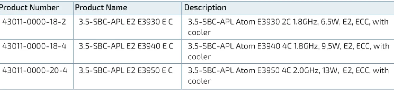
Table 2: Industrial Temperature (-40°C to +85°C)
Product Number Product Name Description
43011-0000-18-2 3.5-SBC-APL E2 E3930 E C 3.5-SBC-APL Atom E3930 2C 1.8GHz, 6,5W, E2, ECC, with cooler
43011-0000-18-4 3.5-SBC-APL E2 E3940 E C 3.5-SBC-APL Atom E3940 4C 1.8GHz, 9,5W, E2, ECC, with cooler
43011-0000-20-4 3.5-SBC-APL E2 E3950 E C 3.5-SBC-APL Atom E3950 4C 2.0GHz, 13W, E2, ECC, with cooler
4/
Product Specification
4.1.
Component Data
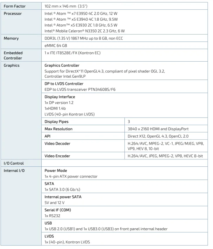
The table below summarizes the features of the 3.5-SBC-APL embedded motherboard. Table 3: Component Data
Form Factor 102 mm x 146 mm (3.5“)
Processor Intel ® Atom ™ x7 E3950 4C 2.0 GHz, 12 W
Intel ® Atom ™ x5 E3940 4C 1.8 GHz, 9.5W Intel ® Atom™ x5 E3930 2C 1.8 GHz, 6.5 W Intel® Mobile Celeron® N3350 2C 2.3 GHz, 6 W
Memory DDR3L (1.35 V) 1867 MHz up to 8 GB, non ECC
eMMC 64 GB Embedded
Controller
1 x ITE IT8528E/FX (Kontron EC)
Graphics Graphics Controller
Support for DirectX*11 OpenGL4.3, compliant of pixel shader OGL 3.2, Controller Intel Gen9LP
DP to LVDS Controller EDP to LVDS transceiver PTN3460BS/F6 Display Interface 1x DP version 1.2 1xHDMI 1.4b LVDS (40-pin Kontron LVDS) Display Pipes 3
Max Resolution 3840 x 2160 HDMI and DisplayPort
API Direct X12, OpenGL 4.3, OpenCL 2.0
Video Decoder H.264/AVC, MPEG-2, VC-1, JPEG/MJEG, VP8,
VP9, HEV 8, 10-bit
Video Encoder H.264/AVC, JPEG, MPEG-2, VP8, HEVC 8-bit
I/O Control
Internal I/O Power Mode
1x 4-pin ATX power connector SATA
1x SATA 3.0 (6 Gb/s) Internal power SATA 5V and 12 V
Serial IF (COM) 1x RS232 USB
1x USB 2.0 (USB1) and 1x USB3.0 (USB3) on front panel internal header LVDS
Fan
1x fan pulse control Front Panel
Power button, Reset button Power LED and Storage LED GPIO
1 x 18 dig I/O Kontron EC GPIO Audio
1 x audio, 1x buzzer
External I/O LAN
2x 10/100/1000 Mbit Ethernet USB 2x USB 3.0 Display Port (DP) 1 x DP version 1.2 HDMI 1x HDMI Expansion Capabilities miniPCIe slot
2x mPCIe (1 x Half size (30 mm x 26,80 mm, pins), 1 x Full size (30 mm x 50,95 mm, 52-pins)
Hardware Status Monitor
onboard & external Fan control, CPU Temp, Fan Speed, Input voltages Four voltages (Vcore, +12 V, +3.3 V, +5 V)
Two temperatures ( CPU temperature, temperature at the center of the motherboard) fan speed
Watchdog Timer Reset; 1 sec. to 255 min. and 1 sec. or 1 min. / step
Wake On Wake on LAN (WoL) S3 – S5, Wake on USB S3 – S5, Power Button (PwrBtn) S3 – S5
Power Supply Power Type
12 V DC input (tolerance +/- 5%) Power Connector
Internal 4-pin connector
Battery BR2032, 195 mAh, 3 V
BIOS BIOS AMI Aptio V UEFI
Operating System Support
Windows 10, Windows® 10 IoT, Windows 7, Linux 64 Bit, VXWorks
Environmentals Operating Temperature
0°C to +60°C operating temperature (forced cooling) Storage Temperature
-40°C to +70°C; lower limit of storage temperature Humidity
50% to 95% relative humidity (non-condensing) from 25°C to 30°C Altitude/ Pressure
4.2.
Standards and Certificates
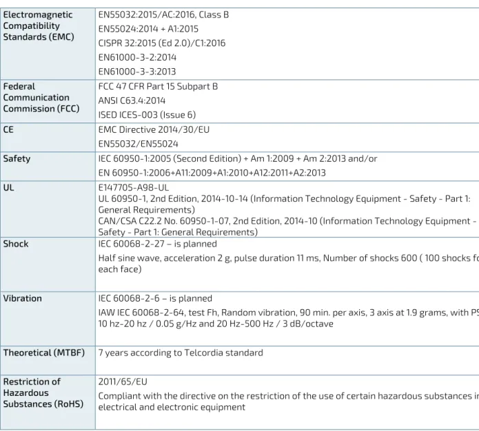
The 3.5-SBC-APL plans to be compliant to the following environmental conditions, and standards and certifications. It is the customer’s responsibility to provide sufficient airflow around each of the components to keep them within allowed temperature range. Refer to the Thermal Simulation report, on Kontron’s Web Page for more information about airflow.
Tests for the standards and certifications mentioned in the table below are current in progress. Table 4: Standards and Certifications
Electromagnetic Compatibility Standards (EMC) EN55032:2015/AC:2016, Class B EN55024:2014 + A1:2015 CISPR 32:2015 (Ed 2.0)/C1:2016 EN61000-3-2:2014 EN61000-3-3:2013 Federal Communication Commission (FCC) FCC 47 CFR Part 15 Subpart B ANSI C63.4:2014
ISED ICES-003 (Issue 6)
CE EMC Directive 2014/30/EU
EN55032/EN55024
Safety IEC 60950-1:2005 (Second Edition) + Am 1:2009 + Am 2:2013 and/or
EN 60950-1:2006+A11:2009+A1:2010+A12:2011+A2:2013
UL E147705-A98-UL
UL 60950-1, 2nd Edition, 2014-10-14 (Information Technology Equipment - Safety - Part 1: General Requirements)
CAN/CSA C22.2 No. 60950-1-07, 2nd Edition, 2014-10 (Information Technology Equipment - Safety - Part 1: General Requirements)
Shock IEC 60068-2-27 – is planned
Half sine wave, acceleration 2 g, pulse duration 11 ms, Number of shocks 600 ( 100 shocks for each face)
Vibration IEC 60068-2-6 – is planned
IAW IEC 60068-2-64, test Fh, Random vibration, 90 min. per axis, 3 axis at 1.9 grams, with PSD 10 hz-20 hz / 0.05 g/Hz and 20 Hz-500 Hz / 3 dB/octave
Theoretical (MTBF) 7 years according to Telcordia standard
Restriction of Hazardous
Substances (RoHS)
2011/65/EU
Compliant with the directive on the restriction of the use of certain hazardous substances in electrical and electronic equipment
4.3.
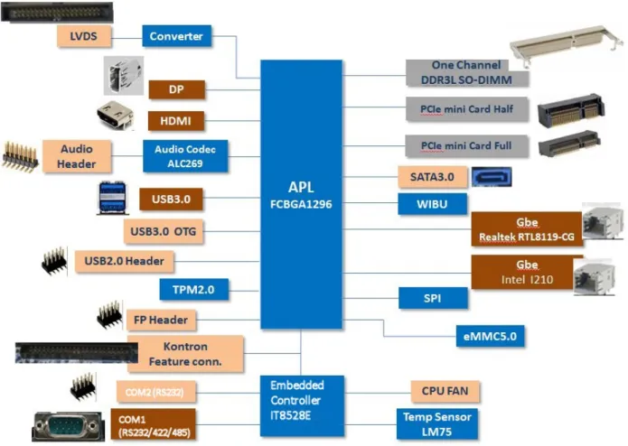
Block Diagram
The following block diagram displays the system architecture of the 3.5-SBC-APL. Figure 1: System Block Diagram
4.4.
Supported Processors
The 3.5-SBC-APL supports the Atom processor family of multicore SoC mobile and the mobile version of the Intel Mobile Celeron N3350 2C.
Intel® 64 Bit Architecture
Intel® Virtualization Technology (VT-x) and Intel® directed I/O Virtualization Technology (VT-d)
Enhanced Intel Speedstep® Technology
Thermal Monitoring Technology
Intel® HD Audio Technologies
Intel® Identity Protection
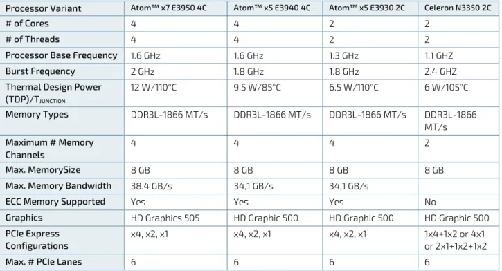
Table 5: Specification of Processor Variants
Processor Variant Atom™ x7 E3950 4C Atom™ x5 E3940 4C Atom™ x5 E3930 2C Celeron N3350 2C
# of Cores 4 4 2 2
# of Threads 4 4 2 2
Processor Base Frequency 1.6 GHz 1.6 GHz 1.3 GHz 1.1 GHZ
Burst Frequency 2 GHz 1.8 GHz 1.8 GHz 2.4 GHZ
Thermal Design Power
(TDP)/TJUNCTION 12 W/110°C 9.5 W/85°C 6.5 W/110°C 6 W/105°C Memory Types DDR3L-1866 MT/s DDR3L-1866 MT/s DDR3L-1866 MT/s DDR3L-1866 MT/s Maximum # Memory Channels 4 4 4 2 Max. MemorySize 8 GB 8 GB 8 GB 8 GB
Max. Memory Bandwidth 38.4 GB/s 34,1 GB/s 34,1 GB/s
ECC Memory Supported Yes Yes Yes No
Graphics HD Graphics 505 HD Graphic 500 HD Graphic 500 HD Graphic 500
PCIe Express Configurations
x4, x2, x1 x4, x2, x1 x4, x2, x1 1x4+1x2 or 4x1
or 2x1+1x2+1x2
Max. # PCIe Lanes 6 6 6 6
4.4.1.
Processor Cooling
The 3.5-SBC-APL supports a combined cooling method with passive or active cooler to provide sufficient cooling to the processor and to remove the effects of TDP (Thermal Design Power). The level of sufficient cooling depends on the worst-case maximum ambient operating temperature and the actual worst-case load of processor. The chipset is cooled via passive cooling.
4.5.
System Memory Support
The 3.5-SBC-APL has 1 GB of soldered down system memory and supports one DDR3L SO-DIMM socket. The sockets support the following memory features:
DDR3L SO-DIMM 1.35 V (non ECC)
1x SO-DIMM DDR3L socket
Maximum support memory up to 8 GB
Memory controller speeds of 1867 MHz
The installed DDR SO-DIMM should support the Serial Presence Detect (SPD) data structure. This allows the BIOS to read and configure the memory controller for optimal performance.
4.6.
Graphics
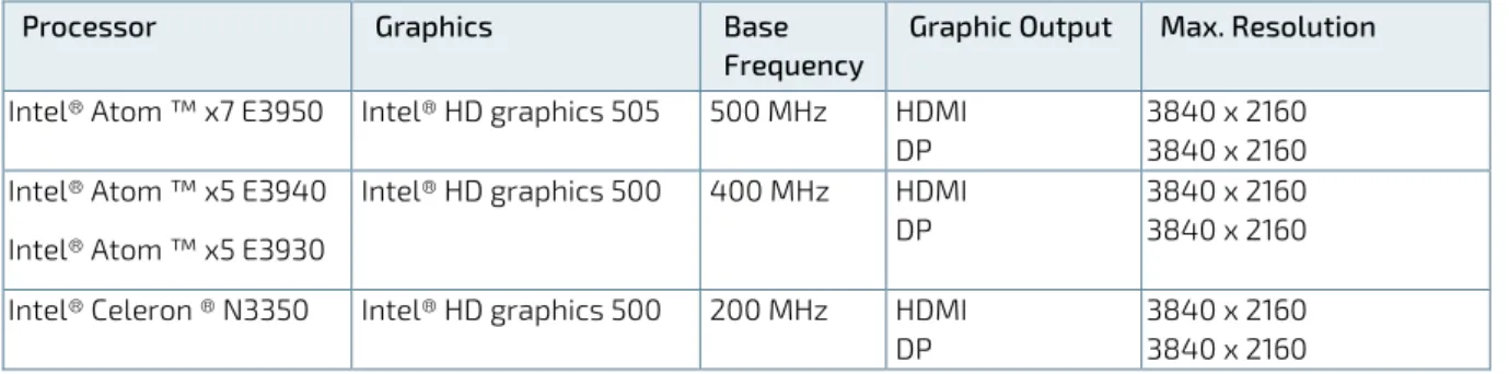
The 3.5-SBS-APL features on-board Intel® HD Graphics (Gen9LP) and supports three display pipes:
DisplayPort (DP)
HDMI
LVDS
Table 6: On-Board Graphics Output
Processor Graphics Base
Frequency
Graphic Output Max. Resolution
Intel® Atom ™ x7 E3950 Intel® HD graphics 505 500 MHz HDMI DP
3840 x 2160 3840 x 2160 Intel® Atom ™ x5 E3940
Intel® Atom ™ x5 E3930
Intel® HD graphics 500 400 MHz HDMI DP
3840 x 2160 3840 x 2160 Intel® Celeron ® N3350 Intel® HD graphics 500 200 MHz HDMI
DP
3840 x 2160 3840 x 2160
4.7.
Power Consumption
In order to ensure safe operation of the board, the input power supply must monitor the supply voltage and shut down if the supply is out of range, refer to the actual power supply specification. In order to keep the power
consumption to a minimal level, boards do not implement a guaranteed minimum load. In some cases, this can lead to compatibility problems with ATX power supplies that require a minimum load to stay in regulation.
The 3.5-SBC-APL is powered by either a single 12 V DC Power Supply or optionally through an internal ATX 4-pin power connector using a standard ATX power supply.
Hot Plugging with the power supply is not supported. Hot plugging might damage the board.
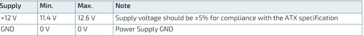
ATX+12 V supply: ATX+12V 4-pin connector must be used in according to the ATX12V PSU standard.
Table 7: Supply Voltage Requirements
Supply Min. Max. Note
+12 V 11.4 V 12.6 V Supply voltage should be ±5% for compliance with the ATX specification
5/
Mainboard views
5.1.
Top Side
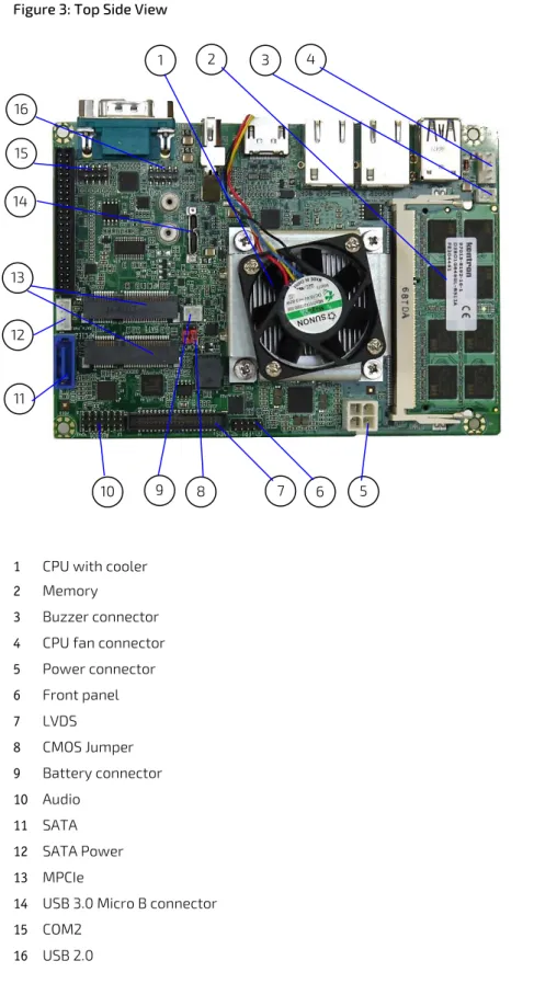
Figure 3: Top Side View
1 CPU with cooler 2 Memory
3 Buzzer connector 4 CPU fan connector 5 Power connector 6 Front panel 7 LVDS 8 CMOS Jumper 9 Battery connector 10 Audio 11 SATA 12 SATA Power 13 MPCIe
14 USB 3.0 Micro B connector 15 COM2 16 USB 2.0 1 2 4 6 5 15 12 11 13 10 7 3 8 9 14 16
5.2.
External I/O Connector Side
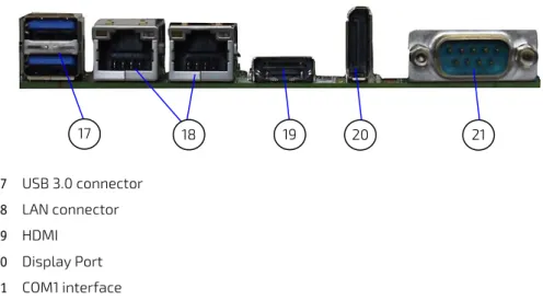
Figure 4: I/O Connector Panel View
17 USB 3.0 connector 18 LAN connector 19 HDMI 20 Display Port 21 COM1 interface 20 19 21 18 17
5.3.
Rear Side
6/
I/O Connectors
6.1.
USB Connectors
The USB 3.0 ports are available via a dual USB connector. USB3.0 ports are backward compatible with USB2.0 Figure 6: Dual stack USB 3.0 Connector
1 9 10 19
Pin Assignment USB Connector
Pin Signal 1 VBUS1 2 U_USB1N_R 3 U_USB1P_R 4 GND 5 USB3_L_RX1_N 6 USB3_L_RX1_P 7 GND 8 USB3_L_TX1_N 9 USB3_L_TX1_P 10 VBUS2 11 U_USB2N_R 12 U_USB2P_R 13 GND 14 USB3_L_RX2_N 15 USB3_L_RX2_P 16 GND 17 USB3_L_TX2_N 18 USB3_L_TX2_P 19 GND
6.2.
Ethernet Connectors
The Ethernet LAN connectors (LAN1 and LAN2) provide two Ethernet ports with 10/100/1000 Mbit Ethernet data transfer rates. MDI means Media Dependent Interface.
Figure 7: Ethernet LAN Connector (RJ45 Female)
Pin Assignment Ethernet LAN connector (LAN1, LAN2)
Pin Signal R1 L_MDIP0 / LAN2_MDI_0 R2 L_MDIN0 / LAN2_MDI_0J R3 L_MDIP1 / LAN2_MDI_1 R4 L_MDIN1 / LAN2_MDI_1J R5 LANxPW1 / LANxPW2 R6 LANxPW1 / LANxPW2 R7 L_MDIP2 / LAN2_MDI_2 R8 L_MDIN2 / LAN2_MDI_2J R9 L_MDIP3 / LAN2_MDI_3 R10 L_MDIN3 / LAN2_MDI_3J L1 LINK100 / LAN2_LED_LINK100 L2 LINK1000 / LAN2_LED_LINK1000 L3 LINKACT / LAN2_LED_LINKACT L4 L_VDD33 / LAN2_VDD33
6.3.
Serial Port Connector (COM1)
The serial port connector (COM1) supports RS232/422/485. Figure 8: Serial Connector
Pin Assignment Serial Connector Pin Signal 1 NDCDA 2 NSINA 3 NSOUTA 4 NDTRA 5 GND 6 NDSRA 7 NRTSA 8 NCTSA 9 NRIA
6.4.
Display Port Connector
The Display Port (DP) connector complies to the Display Port 1.2 standard. Figure 9: Display Port Connector
Pin Signal Pin Signal
1 DDI0_TX0_DP_R 2 GND 3 DDI0_TX0_DN_R 4 DDI0_TX1_DP_R 5 GND 6 DDI0_TX1_DN_R 7 DDI0_TX2_DP_R 8 GND 9 DDI0_TX2_DN_R 10 DDI0_TX3_DP_R 11 GND 12 DDI0_TX3_DN_R 13 DP0_DET 14 GND 15 DPD0_AUX_DP 16 GND 17 DPD0_AUX_DP 18 GND 19 GND 20 +3.3V
6.5.
HDMI Connector
Figure 10: HDMI Graphics Connector
Pin Signal Pin Signal
1 DVITX2+ 2 GND 3 DVITX2- 4 DVITX1+ 5 GND 6 DVITX1- 7 DVITX0+ 8 GND 9 DVITX0- 10 DVITXC+ 11 GND 12 DVITXC- 13 x 14 x 15 HDMIxCLK 16 HDMIxDAT 17 GND 18 +5V 19 HPD_IN 20
7/
Internal Connectors
7.1.
USB Connectors
The following internal USB ports are available:
2x USB 2.0 on the front panel internal header (USB1)
1x micro USB 3.0, type B in the internal header
2x USB 3.0 on the external I/O panel
Figure 11: USB 2.0 Connector (USB1)
Pin Assignment USB1
Pin Signal Pin Signal
1 5VSB 2 5VSB 3 USB_P6_DN_R 4 USB_P7_DN_R 5 USB_P6_DP_R 6 USB_P7_DP_R 7 GND 8 GND 9 10 GND
7.2.
LVDS Connector
The LVDS connector is based on a 40-pin connector and supports either single channel 18 bit / 24 bit LVDS. The LVDS set up can be changed in the BIOS setup.
Figure 12: LVDS 40-Pin Connector
Pin Assignment LVDS 40-Pin Connector
Pin Signal Type Note
1 +12 V PWR Max. 0.5 A 2 +12 V PWR Max. 0.5 A 3 +12 V PWR Max. 0.5 A 4 +12 V PWR Max. 0.5 A 5 +12 V PWR Max. 0.5 A 1 3 5 7 9 11 13 15 17 19 21 23 25 27 29 31 33 35 37 39 2 4 6 8 10 12 14 16 18 20 22 24 26 28 30 32 34 36 38 40
Pin Signal Type Note 6 GND PWR 7 +5 V PWR Max. 0.5 A 8 GND PWR 9 LCDVCC PWR Max. 0.5 A 10 LCDVCC PWR Max. 0.5 A 11 DDC CLK OT 4.7 KΩ, 3.3 V 12 DDC DATA OT 4.7 KΩ, 3.3 V 13 BKLTCTL OT 3.3 V level 14 VDD ENABLE OT 3.3 V level 15 BKLTEN# OT 3.3 V level 16 GND PWR Max. 0.5 A 17 LVDS A0- LVDS 18 LVDS A0+ LVDS 19 LVDS A1- LVDS 20 LVDS A1+ LVDS 21 LVDS A2- LVDS 22 LVDS A2+ LVDS 23 LVDS ACLK- LVDS 24 LVDS ACLK+ LVDS 25 LVDS A3- LVDS 26 LVDS A3+ LVDS 27 GND PWR Max. 0.5 A 28 GND PWR Max. 0.5 A 29 LVDS B0- LVDS 30 LVDS B0+ LVDS 31 LVDS B1- LVDS 32 LVDS B1+ LVDS 33 LVDS B2- LVDS 34 LVDS B2+ LVDS 35 LVDS BCLK- LVDS 36 LVDS BCLK+ LVDS 37 LVDS B3- LVDS 38 LVDS B3+ LVDS 39 GND PWR Max. 0.5 A 40 GND PWR Max. 0.5 A Signal Description
LVDS A0…A3 LVDS A Channel data
LVDS ACLK LVDS A Channel clock
LVDS B0…B3 LVDS B Channel data
LVDS BCLK LVDS B Channel clock
BKLTCTL Backlight control, PWM signal to implement voltage in the range 0 V-3.3 V
BKLTEN# Backlight Enable signal (active low)
VDD ENABLE Output display enable
LCDVCC VCC supply to the display. 5 V or 3.3 V (1 A maximum) selected in BIOS setup menu.
Power sequencing depends on LVDS panel selection.
DDC CLK DDC Channel Clock
7.3.
Internal Serial Por
t (COM2)
The serial port connector COM2 supports one internal serial interface compliant with the RS232 standard. Figure 13: Serial Port Connector (COM2)
1 3 5 7 9
Pin Assignment Serial Port Connector
Pin Signal Pin Signal
1 NDCDB 2 NDSRB
3 NSINB 4 NRTSB
5 NSOUTB 6 NCTSB
7 NDTRB 8 NRIB
9 GND 10
7.4.
SATA Connector (SATA)
The SATA connector supplies a 3 Gbit/s data connection to the SATA hard disk and is SATA 2.0 complaint. Figure 14: SATA Connector
Pin Assignment SATA Connector (SATA)
Pin Signal 1 GND 2 SATA0TXP 3 SATA0TXN 4 GND 5 SATA0RXN 6 SATA0RXP 7 GND 1 2 3 4 5 6 7 2 4 6 8 NC
7.5.
SATA Internal Pow
er(SATA_PWR1)
The SATA power connector (SATA_PWR1) supplies the SATA hard disk with either 12 V or 5 V. Figure 15: SATA Power Internal Connector
Pin Assignment SATA Power (SATA_PWR)
Pin Signal
1 +12V
2 GND
3 GND
4 VCC5
7.6.
Audio Connecto
r (AUDIO1)
The audio connector (AUDIO1) provides audio output, audio inputs and microphone signals. Figure 16: Audio Connector
Pin Assignment Audio Connector (AUDIO1)
Pin Signal Pin Signal
1 A_MIC1_L 2 A_LOUT_L 3 GND 4 GND 5 A_MIC1_JD 6 A_LOUT_JD 7 A_MIC1_R 8 A_LOUT_R 9 GND 10 GND 11 SPK-L-C 12 SPK-R-C 13 SPK-L+C 14 SPK-R+C
7.7.
Buzzer Connect
or (BZ1)
The buzzer connector (BZ1) provides an audio buzzer output signal. Figure 17: Buzzer connector (BZ1)
Pin assignment Buzzer Connector (BZ1)
Pin Signal
1 VCC5
2 SB_HDA_SPKR
7.8.
Front Pane
l (FP1)
The front panel connector supplies signals for the power button, power LED and storage LED. Figure 18: Front Panel Connector
Pin Assignment Front Panel Connector (FP1)
Pin Signal Pin Signal
1 VCC3 2 GND
3 SB_SATA_LED# 4 3VSB
5 GND 6 SB_PWRBTN#
7 EXT_RESET# 8 GND
9 10 NC
7.9.
System Fan Connecto
r (SYS_FAN1)
The system fan connector (SYS_FAN1) is reserved for the system fan with PWM functions. Figure 19: System Fan Connector
1 4
Pin Assignment System Fan Connector (SYS_FAN1) Pin Signal 1 SYS_FAN_CTRL 2 SYS_FAN_TACH 3 +12V 4 GND
7.10.
Power Connec
tor (J1)
The ATX 4-pin internal power supply connector is a standard motherboard power connector providing +12 V DC to the processor voltage regulator.
Hot plugging of the power connectors is not allowed. Hot plugging might damage the board. When connecting to the motherboard, turn off main supply to make sure that all the power lines are turned off.
Figure 20: Internal Power Connector (J1)
Pin Assignment Internal 12 V ATX Power Connector
Pin Signal
1 GND
2 GND
3 DC12V
4 DC12V
7.11.
Mini PCIe Card socket 1 (MPCIE1/2)
Pin Signal Pin Signal 1 WAKE# 2 +3.3V_S5 3 N.C. 4 GND 5 N.C. 6 +1.5V_S0 7 CLKREQ# 8 UIM-PWR 9 GND 10 UIM-DATA 11 PCIe_REFCLK- 12 UIM-CLK 13 PCIe_REFCLK+ 14 UIM-RST 15 GND 16 UIM-VPP 17 UIM-C8 18 GND 19 UIM-C4 20 W_DISABLE# 21 GND 22 PLTRST# 23 PCIe_RX- 24 +3.3V_S5 25 PCIe_RX+ 26 GND 27 GND 28 +1.5V_S0 29 GND 30 PU 3.3V(S5) (Optional: SMB_CLK) 31 PCIe_TX- 32 PU 3.3V(S5) (Optional: SMB_DAT) 33 PCIe_TX+ 34 GND 35 GND 36 USB_D- 37 GND 38 USB_D+ 39 +3.3V_S5 40 GND 41 +3.3V_S5 42 PU 3.3V(S0) 43 GND 44 PU 3.3V(S0) 45 N.C. 46 PU 3.3V(S0) 47 N.C. 48 +1.5V_S0 49 N.C. 50 GND 51 N.C. 52 +3.3V_S5
7.12.
CMOS Internal (CMOS1/2)
Figure 22: CMOS1/CMOS2 Internal Connector 1
Pin Description 1 3V_BATT 2 RTCRST# 3 GND Function: Pin 1-2: Default Pin 2-3: Clear CMOS
8/
BIOS Settings
8.1.
Setup Menus
The Setup utility features for menus listed in the selection bar at the top of the screen:
Main
Advanced
Chipset
Security
Boot
Save & Exit
The Setup menus are selected via the left and right arrow keys. The currently active menu and the currently active uEFI BIOS Setup item are highlighted in white. Each Setup menu provides two main frames. The left frame displays all available functions. Functions that can be configured are displayed in blue. Functions displayed in gray provide information about the status or the operational configuration. The right frame displays an Item Specific Help window providing an explanation of the respective function.
8.2.
Main Setup Menu
Upon entering the uEFI BIOS Setup program, the Main Setup menu is displayed. This screen lists the Main Setup menu sub-screens and provides basic system information as well as functions for setting the system time and date. Table 8: Main Setup Menu Sub-Screens Functions
Sub-Screen Description
BIOS Information Display BIOS Vendor, Core Version, and etc.
Board Information Display Product Name, PCB ID, and etc.
CPU Information Display Name, Type, Speed, and etc.
Memory Information Display Total Memory and Memory Speed
Platform firmware Information Display BXT, MRC, PUNIT, PMC, TXE and GOP
System Language Set System Language
System Date Set System Date
System Time Set System Time
8.3.
Advanced Setup Menu
The Advanced Setup menu provides sub-screens and functions for advanced configuration. Table 9: Advanced Setup Menu Sub-Screens and Functions
Sub-Screen Function Description
Trusted Computing
Security Device Support Enable/Disable BIOS support for
security device
SHA-1 PCR Bank Enable/Disable SHA-1 PCR Bank
SHA256 PCR Bank Enable/Disable SHA256 PCR Bank
Sub-Screen Function Description
Pending Operation Schedule an Operation for the Security
Device
Platform Hierarchy Enable/Disable Platform Hierarchy
Storage Hierarchy Enable/Disable Storage Hierarchy
Endorsement Hierarchy Enable/Disable Endorsement Hierarchy
TPM2.0 UEFI Spec Version Select the TCG2 Spec Version Support,
TCG_1_2: the compatible mode for win8/win10 TCG_2: Support new TCG2 protocol and event format for win10 or later
Physical Presence Spec Version Select to Tell O.S to support PPI Spec
Version 1.2 or 1.3. Note some HCK tests might not support 1.3
Device Select TPM 1.2 will restrict support to TPM 1.2
device, TPM 2.0 will restrict support to TPM 2.0 device, Auto will support both with the default set to TPM 2.0 devices if not found,TPM 1.2 will be enumerated
ACPI Settings Enable ACPI Auto Configuration Enable/Disable BIOS ACPI Auto
Configuration
Enable Hibernation Enable/Disable system ability to
Hibernate (OS/S4 Sleep state). This option may be not effective with some OS
ACPI Sleep State Select the Highest ACPI Sleep state the
system will enter when the SUSPEND button is pressed
LOCK Legacy ressources Enable/Disable Lock of Legacy
Resources SMART
Settings
SMART Self Test Run SMART Self Test on all HDDs during
POST IT8528 Super
IO
Configuration
Serial Port 1 Configuration Serial Port Enable/Disable Serial Port (COM) Device Settings Display Device Settings
Change Settings Select an optimal settings for Super IO Device
Mode Sets RS485 full mode, RS485 half
duplex mode or RS232
Termination Control Select COM1 receiver termination
Serial Port 2 Configuration
Serial Port Enable/Disable Serial Port (COM)
Device Settings Display Device Settings
Change Settings Select an optimal settings for Super IO Device
Sub-Screen Function Description Serial Port Console Redirection Legacy Console Redirection Settings
Legacy Serial Redirection Port
Select a COM port to display redirection of Legacy OS and Legacy OPROM Messages
Console Redirection Enable/Disable Console Redirection
Console Redirection Settings
Terminal Type Emulation: ANSI: Extended ASCII char set. VT100: ASCII char set. VT100+: Extends VT100 to support color, function keys, etc. VT-UTF8: Uses UTF8 encoding to map Unicode
Bits per second Select serial port transmission speed Flow Control Flow control can prevent data loss from
buffer overflow
Data Bits Data Bits
Parity A parity bit can be sent with the data bit
to detect some transmission errors Stop Bits Stops bits indicate the end of a serial
data packet CPU
Configuration
Turbo Mode Enable/Disable Turbo Mode
Intel Virtualization Technology Whe Enabled, a VMM can Utilize the
nadditional hardware capabilities provided by Vanderpool Technology
VT-d Enable/Disable CPU VT-d
Bi-directional PROCHOT When a processor thermal sensor trips
(either core), the PROCHOT# will be driven. If bi-directional is enabled, external agents can drive PROCHOT# to throttle the processor
Monitor Mwait Enable/Disable Monitor Mwait
Network Stack Configuration
Network Stack Enable/Disable UEFI Network Stack
CSM
Configuration
CSM Support Enable/Disable Compatibility Support
Module NVMe
Configuration
NVMe controller and Device information No NVMe Device Found
USB
Configuration
Legacy USB Support Enables Legacy USB support
XHCI Hand-off This is a workaround for OSes without
XHCI hand-off support
USB Mass Storage Driver Support Enable/Disable USB Mass Storage
Driver Support
USB transfer time-out The time-out value for Control, Bulk,
and Interrupt transfer
Sub-Screen Function Description command time-out
Device power-up delay Maximum time for the device will take
before it properly report itself to the Host Controller Platform Trust Technology fTPM Enable/Disable fTPM Security Configuration
TXE HMRFPO Enable/Disable TXE HMRFPO
TXE EOP Message Enable/Disable EOP Message
LVDS
Configuration
LVDS Flat Panel Display Support Enable/Disable LVDS Flat Panel Display
Support
Panel Type Select the type or Manufacturer’s name
of the display panel
Resolution Select the screen resolution of the
display panel
Panel Color Depth Select the display panel color depth
Panel Voltage Select the voltage level for powering the
LVDS Display Panel
Channel Select LVDS Interface Signals mode
Single-Channel or Dual-Channel (Sometimes called “Single-Pixel” or “Dual-Pixel”)
Bus Swapping Swap LVDS interface signals: Normal –
use bus as indicated by pin name, Swapped – swap odd bus signals with even bus signals
Clock Frequency Center Spread Programmable center spreading of pixel
clock frequency to minimize EMI
Differential Output Swing Level Programmable LVDS signal swing to
pre-compensate for channel
attenuation or allow for power saving
Backlight Enable/Disable Backlight
Backlight Signal Inversion Enable – Active High
Disable – Active Low for display panel Backlight signal
Backlight PWM Frequency Set the PWM frequency the backlight
Brightness Level Select the Brightness Level for the
backlight of the display panel
System Temperature Display the System Temperature
System Temperature Offset Adjust the offset value in C (Two’s
Complement)
Sub-Screen Function Description
Hardware Health Configuration
System Fan Speed Display System Fan Speed
Fan Cruise Control Disable = Full speed
Thermal = does regulate fan speed according to specified temperature Speed = does regulate according to specified speed
Watchdog Function 0 = Disable. Enter the service interval in
seconds before the system will reset
ITE8528 Firmware Update This option is enable Auto Update when
version is not match, force update or disable update EC firmware
PC Speaker/Beep Control the default beeps during boot of
the system
Thermal Automatic Thermal Reporting Configure _CRT, _PSV, _ACO
automatically based on values recommended in BWG’s Thermal Reporting for Thermal Management settings. Set to Disabled for manual configuration.
Critical Trip Point This value controls the temperature of
the ACPI Critical Trip Point – the point in which the OS will shut the system off
Passive Trip point This value controls the temperature of
the ACPI Passive Trip Point – the point in which the OS will begin throttling the processor
Active Trip Point This value controls the temperature of
the ACPI Active Trip Point – the point in which the OS will turn the fan on
DPTF Enable/Disable DPTF
System Component
OS Reset Select Select the reset type in FACP table
DDR SSC Enable DDR Spread Spectrum Clocking
configuration
DDR SSC Selecting Table Choose the item in SSC selection table
for DDR spread spectrum
DDR Clock Bending Selection Table Choose for clock bending
HighSpeed SerialIO SSC Enable HighSpeed SerialIO Spread
Spectrum Clocking configuration HighSpeed SerialIO SSC Selection T Choose the item in SSC selection table
for HighSpeed Serial IO spead spectrum RC ACPI
Settings
Native PCIE Enable Enable/Disable Native PCIE Enable
Native ASPM Auto/Enable/Disable Controlled ASPM
RTD3 settings
8.4.
Chipset Setup Menu
The Chipset Setup menu provides information about the configuration. Table 10: Chipset Setup Menu Functions
Sub-Screen Function Description
North Bridge Max Top of Low Usable DRAM (Dynamic Random Access Memory) (TOLUD)
Maximum value of TOLUD Above 4GB MemoryMappedIO (MMIO) BIOS assignment Enable/Disable above 4GB
MemoryMappedIO BIOS assignment
PCIE VGA Workaround Enable if your PCIe card
cannot boot to DOS
South Bridge Serial IRQ Mode Configure Serial IRQ Mode
SMBus Support Enabled/Disabled SMBus
Support
OS selection Select the Target OS
PCI CLOCK RUN Enables CLKRUN# logic to
stop PCI clocks
Real Time Option Select Read-Time Enabled
and IDI Agent Real-Time Traffic Mask Bits Uncore
Configuration
GOP Driver Enable GOP driver will
unload VBIOS; Disable it will load VBIOS
Intel Graphics Pre-EFI Initialization (PEI) Display Peim Enable/Disable Pei (Early) Display
GOP Brightness Level Set GOP Brightness Level;
Value ranges from 0-255
Integrated Graphics Device Enable : Enabled IGD when
selected as the primary Video Adapter. Disable : Always disable IGD
Primary Display Select which of IGD/PCI
Graphics device should be Primary Display
RC6(Render Standby) Check to enable render
standby support, RC6 should be enabled if S0ix is enabled. This item will be read only if S0ix is enabled.
GTT Size Select the GTT Size
Aperture Size Select the Aperture Size
DVMT Pre-Allocated Select DVMT 5.0
Pre-Allocated (Fixed) Graphics Memory size used by the
Sub-Screen Function Description
Internal Graphics Device
DVMT Total Gfx Mem Select DVMT 5.0 Total
Graphics Memory size used by the Internal Graphics Device
Cd Clock Frequency Select the highest Cd Clock
frequency supported by the platform
GT PM Support Enable/Disable GT PM
Support
PAVP Enabled Enable/Disable PAVP
BIA Auto: GMCH Use VBIOS;
Default; Level n: Enabled with selected
Aggressiveness Level
ALS Support Valid only for ACPI
IGD Flat Panel Select IGD Flat panel
Resolution
IGD Boot Type Select preference for IGD
display interface used when system boots.
Panel Scaling Select Panel scaling
GMCH BLC Control Back Light Control Setting
South Cluster Configuration
HD-Audio Configuration HD-Audio Support Enable/Disable HD-Audio
Support
PCI-Express Configuration PCI Express Clock Gating PCI Express Clock Gating Enable/Disable for each root port
Port 8xh Decode PCI express Port8xh Decode
Enable/Disable Peer Memory Write Enable Peer Memory Write
Enable/Disable
Compliance Mode Compliance Mode
Enable/Disable PCIe #0 BDF [00:13:00] LAN1
(Intel I210)
Control the PCI Express Root port PCIe #0 PCIe #1 BDF [00:13:01] LAN1
(RealTek 8119)
Control the PCI Express Root port PCIe #1 PCIe #2 BDF [00:13:02] mPCIe 1 Control the PCI Express
Root port PCIe #2 PCIe #3 BDF [00:13:03] mPCIe 3 Control the PCI Express
Root port PCIe #3
Sub-Screen Function Description
SCC Configuration SCC eMMC Support Enable/Disable SCC eMMC
Support
eMMC Max Speed Select the eMMC max Speed
allowed
USB Configuration XHCI Pre-Boot Driver Enable/Disable XHCI
Pre-Boot Driver support
USB VBUS VBUS should be ON in
HOZST mode. It should be OFF in OTG device mode
USB HSIC1 Support Enable/Disable USB HSIC1
USB SSIC1 Support Enable/Disable USB SSIC1
USB Port Disable Override Selectively Enable/Disable the corresponding USB port from reporting a Device Connection to the controller
XDCI Support Enable/Disable XDCI
XHCI Disable Compliance Mode Options to disable XHCI Link Compliance mode. Default is FALSE to not disable Compliance Mode. Set TRUE to disable Compliance Mode Miscellaneous Configuration High Precision Timer Enable/Disable the High
Precision Event Timer
State After G3 Specify what state to go to
when power is re-applied after a power failure (G3 state).
Power Button Debounce Mode Enable interrupt when PWRBTN# is asserted.
Wake On Lan Enable/Disable the Wake
on Lan
BIOS Lock Enable/Disable the SC BIOS
Lock Enable feature. Required to be enabled to ensure SMM protection of flash.
RTC Lock Enable will lock bytes
38h-3Fh in the lower/upper 128-byte bank of RTC RAM
TCO Lock Enable TCO and Lock Down
TCO
DCI enable (HDCIEN) When DCI enable, it is taken as user consent to enable the DCI which allows debug over the USB3 interface.
Sub-Screen Function Description
When Disabled, the host control is not enabling DCI feature.
GPIO Lock Enable to set GPIO Pad
Configuration Lock for security.
8.5.
Security Setup Menu
The Security Setup menu provides information about the passwords and functions for specifying the security settings. The passwords are case-sensitive.
Table 11: Security Setup Menu Functions
Function Description
Administrator Password Set Setup Administrator Password
User Password Set user password
Secure Boot Attempt Secure Boot Secure Boot Activated when Platform
Keys (PK) is enrolled, system mode is user/deployed, and CSM function is disable
Enter Audit Mode Enter Audit Mode. If current System
Mode is User – PK variable will be erased on transition to Audit
Secure Boot Mode Secure Boot Mode – Custom &
Standard, Set UEFI Secure Boot Mode to STANDARD mode or CUSTOM mode, this change is effect after save. And after reset, the mode will return to STANDARD mode
Key Management Enables expert users to modify Secure
Boot Policy variables without full authentication
8.6.
Boot Setup Menu
The Boot Setup menu lists the for boot device priority order, which is dynamically generated. Table 12: Boot Priority Order
Function Description
Setup Prompt Timeout Number of seconds to wait for setup activation key
Bootup NumLock State Select the keyboard NumLock state
Quiet Boot Enables/Disables Quiet Boot option
Boot Option #1 Sets the system boot order
Function Description time during boot.
SATA Support Select Last Boot HDD only or All Sata Devices
VGA Support If Auto, only install Legacy OpRom with Legacy OS and logo would NOT
be shown during post. Efi driver will still be installed with EFI OS. USB Support If disabled, all USB devices will NOT be available until after OS boot. If
Partial Initial, USB Mass Storage and specific USB port/device will NOT be available before OS boot. If Enabled, all USB devices will be available in OS and Post.
PS2 Devices Support If disabled, PS2 devices will be skipped
Network Stack Driver Support If disabled, Network Stack Driver will be skipped Redirection Support If disabled, Redirection function will be disabled
New Boot Option Policy Controls the placement of newly detected UEFI boot options
8.7.
Save & Exit Setup Menu
The Save & Exit Setup menu provides functions for handling changes made to the UEFI BIOS settings and the exiting of the Setup program.
Table 13: Save & Exit Setup Menu Functions
Function Description
Save Changes and Exit Exit system setup after saving the changes Discard Changes and Exit Exit system setup without saving any changes Save Changes and Reset Reset the system after saving the changes Discard Changes and Reset Reset system setup without saving any changes Save Changes Save changes done so far to any of the setup option Discard Changes Discard changes done so far to any of the setup option Restore Defaults Restore/Load Default values for all the setup option Save as User Defaults Save the changes done so far as User Defaults Restore User Default Restore the User defaults to all the setup option UEFI: Built-in EFI Shell Go to UEFI shell
Launch EFI Shell from filesystem device
Attempts to Launch EFI Shell application (Shell.efi) from one of the available filesystem devices
APPENDIX: LIST OF ACRONYMS
Table 14: List of Acronyms
BMC Base Management Controller
CLI Command-Line Interface
COM Computer-on-Module
ECC Error Checking and Correction FCC Federal Communication Commission FRU Field Replaceable Unit
GPIO General Purpose Input Output
GPU Graphics Processing Unit
HDAC High Definition Audio Codec
IOL IPMI-Over-LAN
IOT Internet of Things
IPMI Intelligent Platform Management
Interface
KCS Keyboard Controller Style
KVM Keyboard Video Mouse
LVDS Low Voltage Differential Signaling
MEI Management Engine Interface
MMIO MemoryMappedIO
MTBF Mean Time Before Failure
NCSI Network Communications Services
Interface
PCIe PCI-Express
PECI Platform Environment Control Interface
RTC Real Time Clock
SATA Serial Advanced Technology Attachment
SEL System Event Log
ShMC Shelf Management Controller
SMBus System Management Bus
SMWI System Monitor Web Interface
SoC System-on-Chip
SOL Serial Over LAN
SSD Solid State Drive
SSH Secure Shell
TDP Thermal Design Power
TOLUD Top of Low Usable DRAM (Dynamic
Random Access Memory) TPM Trusted Platform Module
UEFI Unified Extensible Firmware Interface
VLP Very Low Profile
About Kontron
Kontron, a global leader in embedded computing technology and trusted advisor in Internet of Things (IoT), works closely with its customers, allowing them to focus on their core competencies by offering a complete and integrated portfolio of hardware, software and services designed to help them make the most of their applications.
With a significant percentage of employees in research and development, Kontron creates many of the standards that drive the world’s embedded computing platforms; bringing to life numerous technologies and applications that touch millions of lives. The result is an accelerated time-to-market, reduced total-cost-of-ownership, product longevity and the best possible overall application with leading-edge, highest reliability embedded technology. For more information, please visit: http://www.kontron.com/