Table of Contents
Title Page No.
INTRODUCTION
What is OBD? . . . 1
YOU CAN DO IT! . . . . 2
SAFETY PRECAUTIONS Safety First! . . . 3
ABOUT THE SCAN TOOL Vehicles Covered . . . 5
Battery Replacement . . . 6
Adjustments and Settings . . . 7
SCAN TOOL CONTROLS Controls and Indicators . . . 11
Display Functions . . . 12
ONBOARD DIAGNOSTICS Diagnostic Trouble Codes (DTCs) . . . 15
PREPARATION FOR TESTING Preliminary Vehicle Diagnosis Worksheet . . . 17
Before You Begin . . . 20
Vehicle Service Manuals . . . 21
USING THE SCAN TOOL Code Retrieval Procedure . . . 22
Erasing Diagnostic Trouble Codes (DTCs) . . . 27
I/M Readiness Testing . . . 29
LIVE DATA MODE Viewing Live Data . . . 35
Customizing Live Data (PIDs) . . . 36
Recording (Capturing) Live Data . . . 37
Live Data Playback . . . 42
ADDITIONAL TESTS O2 Sensor Test . . . 44
Non-Continuous Test . . . 46
System Test . . . 47
Vehicle Information . . . 48
GENERIC (GLOBAL) OBD2 PID LIST . . . . 50
GLOSSARY Glossary of Terms and Abbreviations . . . 55
WARRANTY AND SERVICING Limited One Year Warranty . . . 57
Introduction
WHAT IS OBD?
WHAT IS OBD?
The OBD2 Scan Tool is designed to work on all OBD 2 compliant vehicles. All 1996 and newer vehicles (cars, light trucks and
SUVs) sold in the United States are OBD 2 compliant.
One of the most exciting improvements in the automobile industry was the addition of on-board diagnostics (OBD) on vehicles, or in more basic terms, the computer that activates the vehicle’s “CHECK ENGINE” light. OBD 1 was designed to monitor manu-facturer-specific systems on vehicles built from 1981 to 1995. Then came the
develop-ment of OBD 2, which is on all 1996 cars and light trucks sold in the U.S. Like its predecessor, OBD 2 was adopted as part of a government mandate to lower vehicle emissions. But what makes OBD 2 unique is its universal application for all late model cars and trucks - domestic and import. This sophisticated program in the vehicle’s main computer system is designed to detect failures in a range of systems, and can be accessed through a universal OBD 2 port, which is usually found under the dashboard. For all OBD systems, if a problem is found, the computer turns on the “CHECK ENGINE” light to warn the driver, and sets a Diagnostic Trouble Code (DTC) to identify where the problem occurred. A special diagnostic tool, such as the OBD2 Scan Tool, is required to retrieve these codes, which consumers and professionals use as a starting point for repairs.
You Can Do It!
EASY TO USE - EASY TO VIEW - EASY TO DEFINE
Easy To Use . . . .
■ Connect the Scan Tool to the vehi-cle’s test connector.
■ Turn the ignition key "On.”
■ Press the LINK button.
Easy To View . . . .
■ The Scan Tool retrieves stored codes, Freeze Frame data and I/M Readiness status.
■ Codes, I/M Readiness status and Freeze Frame data are displayed on the Scan Tool’s display screen. System sta-tus is indicated by LED indicators.
Easy To Define . . . .
■ Read code definitions from the Scan Tool’s display.
■ View Freeze Frame data.
Safety Precautions
SAFETY FIRST!
SAFETY FIRST!
This manual describes common test procedures used by experienced service technicians. Many test procedures require precautions to avoid accidents that can result in personal injury, and/or damage to your vehicle or test equipment. Always read your vehicle's service manual and follow its safety precautions before and during any test or service procedure. ALWAYS observe the following general safety precautions:
When an engine is running, it produces carbon monox-ide, a toxic and poisonous gas. To prevent serious injury or death from carbon monoxide poisoning, operate the vehicle ONLY in a well-ventilated area.
To protect your eyes from propelled objects as well as hot or caustic liquids, always wear approved safety eye protection.
When an engine is running, many parts (such as the coolant fan, pulleys, fan belt etc.) turn at high speed. To avoid serious injury, always be aware of moving parts. Keep a safe distance from these parts as well as other potentially moving objects.
Engine parts become very hot when the engine is run-ning. To prevent severe burns, avoid contact with hot engine parts.
Before starting an engine for testing or trouble-shoot-ing, make sure the parking brake is engaged. Put the transmission in park (for automatic transmission) or
neutral (for manual transmission). Block the drive
wheels with suitable blocks.
Connecting or disconnecting test equipment when the ignition is ON can damage test equipment and the vehi-cle's electronic components. Turn the ignition OFF before connecting the Scan Tool to or disconnecting the Scan Tool from the vehicle’s Data Link Connector (DLC).
To avoid personal injury, instrument damage and/or damage to your vehicle; do not use the OBD2 Scan Tool
before reading this manual.
N L
D
R
Safety Precautions
SAFETY FIRST!
To prevent damage to the on-board computer when tak-ing vehicle electrical measurements, always use a digi-tal multimeter with at least 10 megOhms of impedance. Fuel and battery vapors are highly flammable. To pre-vent an explosion, keep all sparks, heated items and open flames away from the battery and fuel / fuel vapors. DO NOT SMOKE NEAR THE VEHICLE DUR-ING TESTDUR-ING.
Don't wear loose clothing or jewelry when working on an engine. Loose clothing can become caught in the fan, pulleys, belts, etc. Jewelry is highly conductive, and can cause a severe burn if it makes contact between a power source and ground.
About the Scan Tool
VEHICLES COVERED
VEHICLES COVERED
The OBD2 Scan Tool is designed to work on all OBD 2 compliant vehi-cles. All 1996 and newer vehicles (cars and light trucks) sold in the United States are OBD 2 compliant.
Federal law requires that all 1996 and newer cars and light trucks sold in the United States must be OBD 2 compliant; this includes all Domestic, Asian and European vehicles.
Some 1994 and 1995 vehicles are OBD 2 compliant. To find out if a 1994 or 1995 vehicle is OBD 2 compliant, check the following:
1. The Vehicle Emissions Control Information (VECI) Label. This
label is located under the hood or by the radiator of most vehicles. If the vehicle is OBD 2 compliant, the label will state “OBD II Certified.”
2. Government Regulations require that
all OBD 2 compliant vehicles must have a “common” sixteen-pin Data
Link Connector (DLC).
Some 1994 and 1995 vehicles have 16-pin connectors but are not OBD 2 compliant. Only those vehicles with a Vehicle Emissions Control Label stating “OBD II Certified” are OBD 2 compliant.
Data Link Connector (DLC) Location
The 16-pin DLC is usually located under the instrument panel (dash), within 12 inches (300 mm) of center of the panel, on the driver’s side of most vehicles. It should be eas-ily accessible and visible from
VEHICLE EMISSION CONTROL INFORMATION
VEHICLE
MANUFACTURER
OBD II CERTIFIED ENGINE FAMILY EFN2.6YBT2BA
DISPLACEMENT 2.6L
THIS VEHICLE CONFORMS TO U.S. EPA AND STATE OF CALIFORNIA REGULATIONS APPLICABLE TO 1999 MODEL YEAR NEW TLEV PASSENGER CARS. REFER TO SERVICE MANUAL FOR ADDITIONAL INFORMATION TUNE-UP CONDITIONS: NORMAL OPERATING ENGINE TEMPERATURE, ACCESSORIES OFF, COOLING FAN OFF, TRANSMISSION IN NEUTRAL
SPARK PLUG TYPE NGK BPRE-11
GAP: 1.1MM CATALYST
EXHAUST EMISSIONS STANDARDS STANDARD CATEGORY CERTIFICATION IN-USE TLEV TLEV INTERMEDIATE
OBD II
CERTIFIED
1 2 3 4 5 6 7 8 9 10111213141516About the Scan Tool
VEHICLES COVERED / BATTERY REPLACEMENT
On some Asian and European vehicles the DLC is located behind the “ashtray” (the ashtray must be removed to access it) or on the far left corner of the dash. If the DLC cannot be located, consult the vehicle’s service manual for the location.
BATTERY REPLACEMENT
Replace batteries when the battery symbol is visible on display and/or the 3 LEDS are all lit and no other data is visible on screen.
1. Locate the battery cover on the back of the Scan Tool. 2. Slide the battery cover off (use your fingers).
3. Replace batteries with three AA-size batteries (for longer life, use
Alkaline-type batteries).
4. Reinstall the battery cover on the back of the Scan Tool.
Language Selection After Battery Installation
The first time the Scan Tool is turned on, you must select the desired display language (English, French or Spanish). Select the display lan-guage as follows:
1. Press and hold the POWER/LINK
button for approximately 3 seconds to turn the Scan Tool “ON.”
■ The Select Language screen displays.
2. Use the UP and DOWN but-tons, as necessary, to highlight the desired display language.
3. When the desired display language is
selected, press the ENTER/LD button to confirm your selection.
■ The display shows the "To Link" mes-sage in the selected display lan-guage. Press the POWER/LINK button to turn the Scan Tool "off."
■ After the initial language selection is performed, it as well as other settings can be changed as desired. See ADJUSTMENTS
About the Scan Tool
ADJUSTMENTS AND SETTINGS
ADJUSTMENTS AND SETTINGS
The OBD2 Scan Tool lets you make several adjustments and settings to configure the Scan Tool for your particular needs. The following adjustments and settings are available:
■ DTC Library - Library of OBD2 DTC definitions.
■ Adjust Brightness: Adjusts the brightness of the display screen.
■ Display Backlight: Turns the display backlight on and off.
■ Select Language: Sets the display language for the Scan Tool to
English, French or Spanish.
■ Unit of Measure: Sets the Unit of Measure for the Scan Tool’s
dis-play to USA or metric.
Adjustments and settings can be made only when the Scan Tool is NOT connected to a vehicle.
To enter the MENU Mode:
1. With the Scan Tool “off”, press and hold
the UP button, then press and release the POWER/LINK button.
■ The adjustments and setting MENU displays.
2. Release the UP button.
DO NOT release the UP button until the adjustments and settings MENU is visible on the display.
3. Make adjustments and settings as described in the following
para-graphs.
Searching for a DTC Definition Using the DTC Library 1. Use the UP and DOWN
but-tons, as necessary, to highlight DTC
Library in the MENU, then press the ENTER/LD button.
■ The Enter DTC screen displays. The screen shows the code “P0000”, with the “P” flashing.
2. Use the UP and DOWN buttons, as necessary, to scroll to the desired DTC type (P=Powertrain, U=Network, B=Body, C=Chassis), then press the
About the Scan Tool
ADJUSTMENTS AND SETTINGS
■ The selected character displays “solid”, and the next character begins flashing.
3. Select the remaining characters in the DTC in the same way,
press-ing the DTC SCROLL button to confirm each character. When you have selected all the DTC characters, press the ENTER/LD
button to view the DTC definiition.
■ If you entered a “Generic” DTC (DTCs that start with “P0”, “P2” and some “P3”):
- The selected DTC and DTC defi-nition (if available) show on the Scan Tool’s display.
■ If you entered a “Manufacturer-Specific” DTC (DTCs that start with “P1” and some “P3”):
- The “Select Manufacturer” screen displays.
- Use the UP and DOWN buttons, as necessary, to high-light the appropriate manufactur-er, then press the ENTER/LD button to display the correct DTC for your vehicle.
If a definition for the DTC you entered is not available, an advi-sory message shows on the Scan Tool’s display.
4. If you wish to view definitions for additional DTCs, press the ENTER/LD button to return to the Enter DTC screen, and repeat steps 2 and 3.
5. When all desired DTCs have been viewed, press the ERASE
button to exit the DTC Library.
Adjusting Display Brightness
1. Use the UP and DOWN but-tons, as necessary, to highlight Adjust
Brightness in the MENU, then press
the ENTER/LD button.
■ The Adjust Brightness screen dis-plays.
About the Scan Tool
ADJUSTMENTS AND SETTINGS
■ The Brightness field shows the cur-rent brightness setting, from 0 to 43.
2. Press the UP button to decrease the brightness of the display (make the display darker).
3. Press the DOWN button to increase the brightness of the display (make the display lighter).
4. When the desired brightness is obtained, press the ENTER/LD
button to save your changes and return to the MENU.
Using the Backlight
1. Use the UP and DOWN but-tons, as necessary, to highlight Display
Backlight in the MENU, then press the ENTER/LD button.
■ The Display Backlight screen displays.
2. Press the UP or DOWN button, as necessary, to select the desired backlight mode, either ON or OFF.
3. When the desired backlight mode is
selected, press the ENTER/LD button to save your changes.
■ The display returns to the MENU, and the backlight turns “on” or “off” as selected.
Selecting the Display Language 1. Use the UP and DOWN
but-tons, as necessary, to highlight Select
Language in the MENU, then press the ENTER/LD button.
■ The Select Language screen dis-plays.
■ The currently selected display
Language is highlighted.
2. Press the UP or DOWN button, as necessary, to highlight the desired display language.
About the Scan Tool
ADJUSTMENTS AND SETTINGS
Setting the Unit of Measurement 1. Use the UP and DOWN but-tons, as necessary, to highlight Unit of
Measurement in the MENU, then press
the ENTER/LD button.
2. Press the UP or DOWN button, as necessary, to highlight the desired
Unit of Measurement.
3. When the desired Unit of Measurement
value is selected, press the ENTER/LD button to save your changes.
Exiting the MENU Mode
1. Use the UP and DOWN buttons, as necessary, to highlight
Menu Exit in the MENU, then press the ENTER/LD button.
■ The display returns to the DTC screen (if data is currently stored in the Scan Tool) or to the "To Link" message (if no data is cur-rently stored in the Scan Tool).
Scan Tool Controls
CONTROLS AND INDICATORS
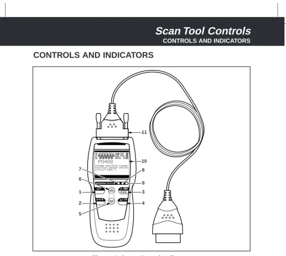
CONTROLS AND INDICATORS
See Figure 1 for the locations of items 1 through 11, below.
1. ERASE button - Erases Diagnostic Trouble Codes (DTCs),
and “Freeze Frame” data from your vehicle’s computer, and resets Monitor status.
2. DTC SCROLL button - Displays the DTC View screen and/or
scrolls the display to view DTCs when more than one DTC is present.
3. POWER/LINK button - When the Scan Tool IS NOT
connected to a vehicle, turns the Scan Tool “On” and “Off”. When the Scan Tool is connected to a vehicle, links the Scan Tool to the vehicle’s PCM to retrieve diagnostic data from the computer’s memory.
To turn the Scan Tool "On", you must press and hold the
POWER/LINK button for approximately 3 seconds.
4. ENTER/LIVE DATA button - When in MENU mode, confirms
the selected option or value. When linked to a vehicle, places the Scan 1 6 7 2 5 3 9 8 4 10 11
Scan Tool Controls
DISPLAY FUNCTIONS
5. DOWN button - When in MENU mode, scrolls DOWN through
the menu and submenu selection options. When LINKED to a vehicle, scrolls DOWN through the current display screen to display any addi-tional data.
6. UP button - When in MENU mode, scrolls UP through the
menu and submenu selection options. When LINKED to a vehicle, scrolls UP through the current display screen to display any additional data.
7. GREEN LED - Indicates that all engine systems are running
nor-mally (all Monitors on the vehicle are active and performing their diag-nostic testing, and no DTCs are present).
8. YELLOW LED - Indicates there is a possible problem. A “Pending”
DTC is present and/or some of the vehicle’s emission monitors have not run their diagnostic testing.
9. RED LED - Indicates there is a problem in one or more of the
vehi-cle’s systems. The red LED is also used to show that DTC(s) are pres-ent. DTCs are shown on the Scan Tool’s display. In this case, the Multifunction Indicator (“Check Engine”) lamp on the vehicle’s instru-ment panel will light steady on.
10. Display - Displays settings Menu and submenus, test results,
Scan Tool functions and Monitor status information. See DISPLAY
FUNCTIONS, following, for more details.
11. CABLE - Connects the Scan Tool to the vehicle’s Data Link
Connector (DLC).
DISPLAY FUNCTIONS
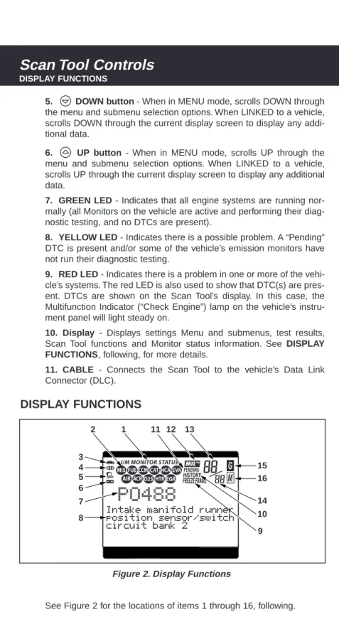
See Figure 2 for the locations of items 1 through 16, following.
4 3 2 1 11 12 13 5 8 9 10 14 16 15 6 7
Scan Tool Controls
DISPLAY FUNCTIONS 1. I/M MONITOR STATUS field - Identifies the I/M Monitor status area. 2. Monitor icons - Indicate which Monitors are supported by the
vehi-cle under test, and whether or not the associated Monitor has run its diagnostic testing (Monitor status). When a Monitor icon is solid, it indicates that the associated Monitor has completed its diagnos-tic testing. When a Monitor icon is flashing, it indicates that the vehi-cle supports the associated Monitor, but the Monitor has not yet run its diagnostic testing.
3. Vehicle icon - Indicates whether or not the Scan Tool is being
properly powered through the vehicle’s Data Link Connector (DLC). A visible icon indicates that the Scan Tool is being powered through the vehicle’s DLC connector.
4. Link icon - Indicates whether or not the Scan Tool is
commu-nicating (linked) with the vehicle’s on-board computer. When visible, the Scan Tool is communicating with the computer. If the Link icon is not visible, the Scan Tool is not communicating with the computer.
5. Computer icon - When this icon is visible it indicates that the
Scan Tool is linked to a personal computer. An optional “PC Link Kit” is available that makes it possible to upload retrieved data to a personal computer.
6. Scan Tool Internal Battery icon - When visible, indicates the
Scan Tool batteries are “low” and should be replaced. If the batter-ies are not replaced when the battery symbol is "on", all 3 LEDs will light up as a last resort indicator to warn you that the batteries need replacement. No data will be displayed on screen when all 3 LEDs are lit.
7. DTC Display Area - Displays the Diagnostic Trouble Code (DTC)
num-ber. Each fault is assigned a code number that is specific to that fault.
8. Test Data Display Area - Displays DTC definitions, Freeze Frame
data, Live Data and other pertinent test information messages.
9. FREEZE FRAME icon - Indicates that there is Freeze Frame data
from “Priority Code” (Code #1) stored in the vehicle’s computer memory.
10. HISTORY icon - Indicates the currently displayed DTC is a
“History” code.
11. PENDING icon - Indicates the currently displayed DTC is a
“Pending” code.
12. MIL icon - Indicates the status of the Malfunction Indicator Lamp
(MIL). The MIL icon is visible only when a DTC has commanded the MIL on the vehicle’s dashboard to light.
Scan Tool Controls
DISPLAY FUNCTIONS
13. Code Number Sequence - The Scan Tool assigns a sequence
number to each DTC that is present in the computer’s memory, starting with “01.” This number indicates which code is currently displayed. Code number “01” is always the highest priority code, and the one for which “Freeze Frame” data has been stored.
If “01” is a “Pending” code, there may or may not be “Freeze Frame” data stored in memory.
14. Code Enumerator - Indicates the total number of codes retrieved
from the vehicle’s computer.
15. Generic DTC icon - When visible, indicates that the currently
displayed DTC is a “generic” or universal code.
16. Manufacturer Specific DTC icon - When visible, indicates that
Onboard Diagnostics
DIAGNOSTIC TROUBLE CODES (DTCs)
DIAGNOSTIC TROUBLE CODES (DTCs)
Diagnostic Trouble Codes (DTCs) are meant to guide you to the proper serv-ice procedure in the vehicle’s servserv-ice manual. DO NOT replace parts based only on DTCs without first consulting the vehicle’s service manual for prop-er testing procedures for that particular system, circuit or component.
DTCs are alphanumeric codes that are used to identify a problem that is present in any of the systems that are mon-itored by the on-board computer (PCM). Each trouble code has an assigned message that identifies the circuit, compo-nent or system area where the problem was found.
OBD 2 diagnostic trouble codes are made up of five charac-ters:
■ The 1st character is a letter. It identifies the “main system” where the fault occurred (Body, Chassis, Powertrain, or Network).
■ The 2nd character is a numeric digit. It identifies the “type” of code (Generic or Manufacturer-Specific).
Generic DTCs are codes that are used by all vehicle
manu-facturers. The standards for generic DTCs, as well as their definitions, are set by the Society of Automotive Engineers (SAE).
Manufacturer-Specific DTCs are codes that are controlled
by the vehicle manufacturers. The Federal Government does not require vehicle manufacturers to go beyond the stan-dardized generic DTCs in order to comply with the new OBD2 emissions standards. However, manufacturers are free to expand beyond the standardized codes to make their sys-tems easier to diagnose.
■ The 3rd character is a numeric digit. It identifies the specific sys-tem or sub-syssys-tem where the problem is located.
■ The 4th and 5th characters are numeric digits. They identify the section of the system that is malfunctioning.
Diagnostic Trouble Codes (DTCs) are codes that identify a specific problem area.
Onboard Diagnostics
DIAGNOSTIC TROUBLE CODES (DTCs)
DTCs and MIL Status
When the vehicle’s on-board computer detects a failure in an emissions-related component or system, the computer’s internal diagnostic program assigns a diagnostic trouble code (DTC) that points to the system (and sub-system) where the fault was found. The diag-nostic program saves the code in the com-puter’s memory. It records a “Freeze Frame” of
conditions present when the fault was found, and lights the Malfunction Indicator Lamp (MIL). Some faults require detection for two trips in a row before the MIL is turned on.
The “Malfunction Indicator Lamp” (MIL) is the accepted term used to describe the lamp on the dashboard that lights to warn the driver that an emissions-related fault has been found. Some manufacturers may still call this lamp a “Check Engine” or “Service Engine Soon” light.
P 0 2 0 1
B C P U -Body Chassis Powertrain Network -Generic Manufacturer Specific GenericIncludes both Generic and Manufacturer Specific Codes
0 1 2 3
Identifies what section of the system is malfunctioning
Identifies the system where the problem is located: 1 2 3 4 5 6 7 8
-Fuel and Air Metering
Fuel and Air Metering (injector circuit malfunction only)
Ignition System or Misfire Auxiliary Emission Control System Vehicle Speed Control and Idle Control System
Computer Output Circuits Transmission
Transmission
OBD 2 DTC EXAMPLE
Preparation for Testing
PRELIMINARY VEHICLE DIAGNOSIS WORKSHEET
PRELIMINARY VEHICLE DIAGNOSIS WORKSHEET
The purpose of this form is to help you gather preliminary information on your vehicle before you retrieve codes. By having a complete account of your vehicle's current problem(s), you will be able to systematically pin-point the problem(s) by comparing your answers to the fault codes you retrieve. You can also provide this information to your mechanic to assist in diagnosis and help avoid costly and unnecessary repairs. It is impor-tant for you to complete this form to help you and/or your mechanic have a clear understanding of your vehicle's problems.NAME: DATE: VIN*: YEAR: MAKE: MODEL: ENGINE SIZE: VEHICLE MILEAGE:
*VIN: Vehicle Identification Number, found at the base of the windshield on a metallic plate, or at the driver door latch area (consult your vehicle owner's manual for location).
TRANSMISSION:
❑ Automatic
❑ Manual
Please check all applicable items in each category. DESCRIBE THE PROBLEM:
Preparation for Testing
PRELIMINARY VEHICLE DIAGNOSIS WORKSHEET
WHEN DID YOU FIRST NOTICE THE PROBLEM:
❑ Just Started
❑ Started Last Week
❑ Started Last Month
❑ Other:
LIST ANY REPAIRS DONE IN THE PAST SIX MONTHS:
PROBLEMS STARTING
ENGINE QUITS OR STALLS
IDLING CONDITIONS
RUNNING CONDITIONS
❑ No symptoms
❑ Will not crank
❑ Cranks, but will not start
❑ Starts, but takes a long time
❑ No symptoms
❑ Right after starting
❑ When shifting into gear
❑ During steady-speed driving
❑ Right after vehicle comes to a stop
❑ While idling
❑ During acceleration
❑ When parking
❑ No symptoms
❑ Is too slow at all times
❑ Is too fast
❑ Is sometimes too fast or too slow
❑ Is rough or uneven
❑ Fluctuates up and down
❑ No symptoms
❑ Runs rough
❑ Lacks power
❑ Bucks and jerks
❑ Poor fuel economy
❑ Hesitates or stumbles on accelerations
❑ Backfires
❑ Misfires or cuts out
❑ Engine knocks, pings or rattles
❑ Surges
Preparation for Testing
PRELIMINARY VEHICLE DIAGNOSIS WORKSHEET
AUTOMATIC TRANSMISSION PROBLEMS (if applicable)
PROBLEM OCCURS
❑ Morning ❑ Afternoon ❑ Anytime
ENGINE TEMPERATURE WHEN PROBLEM OCCURS
❑ Cold ❑ Warm ❑ Hot
DRIVING CONDITIONS WHEN PROBLEM OCCURS
DRIVING HABITS
GASOLINE USED
WEATHER CONDITIONS WHEN PROBLEM OCCURS
CHECK ENGINE LIGHT / DASH WARNING LIGHT
❑ Sometimes ON ❑ Always ON ❑ Never ON
PECULIAR SMELLS
STRANGE NOISES
❑ Short - less than 2 miles
❑ 2 - 10 miles
❑ Long - more than 10 miles
❑ Stop and go
❑ While turning
❑ While braking
❑ At gear engagement
❑ With A/C operating
❑ With headlights on
❑ During acceleration
❑ Mostly driving downhill
❑ Mostly driving uphill
❑ Mostly driving level
❑ Mostly driving curvy roads
❑ Mostly driving rough roads
❑ Mostly city driving
❑ Highway
❑ Park vehicle inside
❑ Park vehicle outside
❑ Drive less than 10 miles per day
❑ Drive 10 to 50 miles per day
❑ Drive more than 50 miles per day
❑ 87 Octane
❑ 89 Octane
❑ 91 Octane
❑ More than 91 Octane
❑ 32 - 55° F (0 - 13° C)
❑ Below freezing (32° F / 0° C)
❑ Above 55° F (13° C)
❑ "Hot"
❑ Sulfur ("rotten egg")
❑ Burning rubber
❑ Gasoline
❑ Burning oil
❑ Electrical
❑ No symptoms
❑ Shifts too early or too late
❑ Changes gear incorrectly
❑ Vehicle does not move when in gear
Preparation for Testing
BEFORE YOU BEGIN
BEFORE YOU BEGIN
The OBD2 Scan Tool aids in monitoring electronic- and emissions-related faults in your vehicle and retrieving fault codes related to malfunc-tions in these systems. Mechanical problems such as low oil level or damaged
hoses, wiring or electrical connectors can cause poor engine perform-ance and may also cause a fault code to set. Fix any known mechan-ical problems before performing any test. See your vehicle’s service manual or a mechanic for more information.
Check the following areas before starting any test:
■ Check the engine oil, power steering fluid, transmission fluid (if applicable), engine coolant and other fluids for proper levels. Top off low fluid levels if needed.
■ Make sure the air filter is clean and in good condition. Make sure all air filter ducts are properly connected. Check the air filter ducts for holes, rips or cracks.
■ Make sure all engine belts are in good condition. Check for cracked, torn, brittle, loose or missing belts.
■ Make sure mechanical linkages to engine sensors (throttle, gearshift position, transmission, etc.) are secure and properly con-nected. See your vehicle’s service manual for locations.
■ Check all rubber hoses (radiator) and steel hoses (vacuum/fuel) for leaks, cracks, blockage or other damage. Make sure all hoses are routed and connected properly.
■ Make sure all spark plugs are clean and in good condition. Check for damaged, loose, disconnected or missing spark plug wires.
■ Make sure the battery terminals are clean and tight. Check for cor-rosion or broken connections. Check for proper battery and charg-ing system voltages.
■ Check all electrical wiring and harnesses for proper connection. Make sure wire insulation is in good condition, and there are no bare wires.
■ Make sure the engine is mechanically sound. If needed, perform a compression check, engine vacuum check, timing check (if applica-ble), etc.
Preparation for Testing
VEHICLE SERVICE MANUALS
VEHICLE SERVICE MANUALS
Always refer to the manufacturer’s service manual for your vehicle before performing any test or repair procedures. Contact your local car dealership, auto parts store or bookstore for availability of these man-uals. The following companies publish valuable repair manuals:
■ Haynes Publications
861 Lawrence Drive
Newbury Park, California 91320 Phone: 800-442-9637 ■ Mitchell International 14145 Danielson Street Poway, California 92064 Phone: 888-724-6742 ■ Motor Publications
5600 Crooks Road, Suite 200 Troy, Michigan 48098 Phone: 800-426-6867
FACTORY SOURCES
Ford, GM, Chrysler, Honda, Isuzu, Hyundai and Subaru Service Manuals
■ Helm Inc.
14310 Hamilton Avenue Highland Park, Michigan 48203 Phone: 800-782-4356
Using the Scan Tool
CODE RETRIEVAL PROCEDURE
CODE RETRIEVAL PROCEDURE
Never replace a part based only on the DTC definition.
Each DTC has a set of testing procedures, instructions and flow charts that must be followed to confirm the loca-tion of the problem. This informaloca-tion is found in the vehicle's service manual. Always refer to the vehicle's service manual for detailed testing instructions.
Check your vehicle thoroughly before performing any test. See Before You Begin on page 20 for details.
ALWAYS observe safety precautions whenever working on a
vehicle. See Safety Precautions on page 3 for more infor-mation.
1. Turn the ignition off.
2. Locate the vehicle's 16-pin Data Link
Connector (DLC). See page 5 for con-nector location.
Some DLCs have a plastic cover that must be removed before necting the Scan Tool cable con-nector.
If the Scan Tool is ON, turn it OFF by pressing the POWER/LINK button BEFORE connecting the Scan Tool to the DLC.
3. Connect the Scan Tool cable connector to the vehicle’s DLC. The
cable connector is keyed and will only fit one way.
■ If you have problems connecting the cable connector to the DLC, rotate the connector 180° and try again.
■ If you still have problems, check the DLC on the vehicle and on the Scan Tool. Refer to your vehicle’s service manual to properly check the vehicle’s DLC.
4. When the Scan Tool’s cable connector is
properly connected to the vehicle’s DLC, the unit automatically turns ON, and the display shows instructions for linking to the vehicle’s on-board computer.
Retrieving and using Diagnostic Trouble Codes (DTCs) for troubleshooting vehicle operation is only one part of an
Using the Scan Tool
CODE RETRIEVAL PROCEDURE
■ If the unit does not power on automatically when connected to the vehicle’s DLC connector, it usually indicates there is no power present at the vehicle’s DLC connector. Check your fuse panel and replace any burned-out fuses.
■ If replacing the fuse(s) does not correct the problem, consult your vehicle’s repair manual to identify the proper computer (PCM) fuse/ circuit, and perform any necessary repairs before proceeding.
5. Turn the ignition on. DO NOT start the engine.
6. Press and release the Scan Tool’s POWER/LINK button.
■ The Scan Tool will automatically start a check of the vehicle’s computer to determine which type of communica-tion protocol it is using. When the Scan Tool identifies the computer’s communication protocol, a communi-cation link is established. The proto-col type used by the vehicle’s com-puter is shown on the display.
A PROTOCOL is a set of rules and procedures for regu-lating data transmission between computers, and between testing equipment and computers. As of this writing, five different types of protocols (ISO 9141, Keyword 2000, J1850 PWM, J1850 VPW and CAN) are in use by vehicle manufacturers. The Scan Tool automatically identifies the protocol type and establishes a communication link with the vehicle’s computer.
7. After approximately 10~60 seconds, the Scan Tool will retrieve and display any Diagnostic Trouble Codes, Monitor Status and Freeze
Frame Data retrieved from the vehicle’s computer memory.
■ If the Scan Tool fails to link to the vehi-cle’s computer a “Linking Failed” mes-sage shows on the Scan Tool’s dis-play.
- Verify the connection at the DLC: and verify the ignition is ON. - Turn the ignition OFF, wait 5
sec-onds, then turn back ON to reset the computer.
- Ensure your vehicle is OBD2 compliant. See Vehicles
Covered on page 5 for vehicle compliance verification
Using the Scan Tool
CODE RETRIEVAL PROCEDURE
■ The Scan Tool will display a code only if codes are present in the vehicle’s computer memory. If no codes are present, a “No DTC’s are presently stored in the vehicle’s computer” message is displayed.
■ The Scan Tool is capable of retrieving and storing up to 32 codes in memo-ry, for immediate or later viewing.
8. To read the display:
Refer to Display Functions on page 12 for a description of display elements.
■ A visible icon indicates that the Scan Tool is being powered through the vehicle’s DLC connector.
■ A visible icon indicates that the Scan Tool is linked to (com-municating with) the vehicle’s computer.
■ The I/M Monitor Status icons indicate the type and number of Monitors the vehicle supports, and provides indications of the current status of the vehicle’s Monitors. A solid Monitor icon indi-cates the associated Monitor has run and completed its testing. A blinking Monitor icon indicates the associated Monitor has
not run and completed its testing.
■ The upper right hand corner of the display shows the number of the code currently being displayed, the total number of codes retrieved, the type of code (G = Generic; M = Enhanced or Manufacturer specific), and whether or not the displayed code commanded the MIL on. If the code
being displayed is a PENDING code, the PENDING icon is shown.
■ The Diagnostic Trouble Code (DTC) and related code definition are shown in the lower section of the display.
In the case of long code definitions, or when viewing Freeze Frame and Live Data, a small arrow is shown in the upper/lower right-hand corner of the Scan Tool dis-play area to indicate the presence of additional infor-mation. Use the and buttons, as necessary, to view the additional information.
9. Read and interpret Diagnostic Trouble Codes/system condition
using the display and the green, yellow and red LEDs.
The green, yellow and red LEDs are used (with the dis-play) as visual aids to make it easier to determine engine system conditions.
Using the Scan Tool
CODE RETRIEVAL PROCEDURE
■ Green LED – Indicates that all
engine systems are “OK” and operat-ing normally. All monitors supported by the vehicle have run and per-formed their diagnostic testing, and no trouble codes are present. A zero will show on the Scan Tool’s display, and all Monitor icons will be solid.
■ Yellow LED – Indicates one of the following conditions: A. A PENDING CODE IS PRESENT – If
the yellow LED is illuminated, it may indicate a Pending code is present. Check the Scan Tool’s display for confirmation. A Pending code is con-firmed by the presence of a numeric code and the word PENDING on the Scan Tool’s display.
B. MONITOR NOT RUN STATUS – If the
Scan Tool’s display shows a zero (indicating there are no DTC’s pres-ent in the vehicle’s computer memo-ry), but the yellow LED is illuminated, it may be an indication that some of the Monitors supported by the vehicle have not yet run and completed their diagnostic testing. Check the Scan Tool’s display for confirmation. All
Monitor icons that are blinking have not yet run and completed their diagnostic testing; all Monitor icons that are solid have run and completed their diagnostic testing.
■ Red LED – Indicates there is a
prob-lem with one or more of the vehicle’s systems. The red LED is also used to indicate that DTC(s) are present (dis-played on the Scan Tool’s screen). In this case, the Multifunction Indicator (Check Engine) lamp on the vehicle’s instrument panel will be illuminated.
■ DTC’s that start with “P0”, “P2” and some “P3” are considered Generic (Universal). All Generic DTC definitions are the same on all OBD2 equipped vehicles. The Scan Tool automatically dis-plays the code definitions (if available) for Generic DTC’s.
Using the Scan Tool
CODE RETRIEVAL PROCEDURE
■ DTC’s that start with “P1” and some “P3” are Enhanced (Manufacturer spe-cific) codes and their code definitions vary with each vehicle manufacturer. When an Enhanced (Manufacturer specific) DTC is retrieved, the LCD dis-play shows a list of vehicle manufactur-ers. Use the UP and DOWN
buttons, as necessary, to highlight the appropriate manufacturer, then press the ENTER/LD button to display the correct code definition for your vehicle.
If the manufacturer for your vehicle is not listed, use the
UP and DOWN buttons, as necessary, to select
Other manufacturer and press the ENTER/LD
but-ton for additional DTC information. If the Manufacturer Specific definition for the currently dis-played code is not available, an advisory message shows on the Scan Tool’s display.
10. If more than one DTC was retrieved,
and to view Freeze Frame Data, press
and release the DTC SCROLL button, as necessary.
■ Each time the DTC SCROLL button is pressed and released, the Scan Tool will scroll and display the next DTC in sequence until all DTCs in its memory have displayed.
■ Freeze Frame Data (if available) will display after DTC #1.
Whenever the Scroll function is used to view additional DTCs and Freeze Frame Data, the Scan Tool's communi-cation link with the vehicle's computer disconnects. To re-establish communication, press the POWER/LINK button again.
■ In OBD2 systems, when an emis-sions-related engine malfunction occurs that causes a DTC to set, a record or snapshot of engine condi-tions at the time that the malfunction occurred is also saved in the vehi-cle’s computer memory. The record saved is called Freeze Frame data.
Saved engine conditions include, but are not limited to: engine speed, open or closed loop operation, fuel system commands, coolant temperature, calculated load value, fuel pressure, vehi-cle speed, air flow rate, and intake manifold pressure.
Using the Scan Tool
ERASING DIAGNOSTIC TROUBLE CODES (DTCs)
If more than one malfunction is present that causes more than one DTC to be set, only the code with the highest pri-ority will contain Freeze Frame data. The code designated “01” on the Scan Tool display is referred to as the PRIORITY code, and Freeze Frame data always refers to this code. The priority code is also the one that has com-manded the MIL on.
Retrieved information can be uploaded to a Personal Computer (PC) with the use of an optional “PC Link Kit.” (see instructions included with PC-Link program for more information).
11. Determine engine system(s) condition by viewing the Scan Tool’s
display for any retrieved Diagnostic Trouble Codes, code defini-tions, Freeze Frame data and Live Data, interpreting the green, yel-low and red LEDs.
■ If DTC’s were retrieved and you are going to perform the repairs yourself, proceed by consulting the Vehicle’s Service Repair Manual for testing instructions, testing procedures, and flow charts related to retrieved code(s).
■ If you plan to take the vehicle to a professional to have it serv-iced, complete the Preliminary Vehicle Diagnosis Worksheet on page 17 and take it together with the retrieved codes, freeze frame data and LED information to aid in the troubleshooting procedure.
■ To prolong battery life, the Scan Tool automatically shuts “Off” approximately three minutes after it is disconnected from the vehicle. The DTCs retrieved, captured Live Data Information, Monitor Status and Freeze Frame data (if any) will remain in the Scan Tool’s memory, and may be viewed at any time by turning the unit “On”. If the Scan Tool’s batteries are removed, or if the Scan Tool is re-linked to a vehicle to retrieve codes/data, any prior codes/data in its memory are automatically cleared.
ERASING DIAGNOSTIC TROUBLE CODES (DTCs)
When the Scan Tool’s ERASE function is used to erase DTCs from the vehicle's on-board computer, "Freeze Frame" data and manufacturer-specific enhanced data are also erased.
If you plan to take the vehicle to a Service Center for repair, DO NOT erase the codes from the vehicle's computer. If the codes are erased, valuable information that might help the technician troubleshoot the problem will also be erased.
When DTCs are erased from the vehicle's computer memo-ry, the I/M Readiness Monitor Status program resets the sta-tus of all Monitors to a not run "flashing" condition. To set all of the Monitors to a DONE status, an OBD 2 Drive Cycle must be performed. Refer to your vehicle's service manual for information on how to perform an OBD 2 Drive Cycle for the vehicle under test.
The Scan Tool must be connected to the vehicle’s DLC to erase the codes from the computer’s memo-ry. If you press the ERASE button when the Scan Tool is not connected to the vehicle’s DLC, the erase instruction screen dis-plays.
1. If not connected already, connect the
Scan Tool to the vehicle's DLC, and turn the ignition "On.” (If the Scan Tool is already connected and linked to the vehicle's computer, proceed directly to step 4. If not, continue to step 2.)
2. Turn the ignition on. DO NOT start the
engine. Press and release the
POWER/LINK button to establish communication with the vehicle's com-puter.
3. Press and release the ERASE but-ton. A confirmation message shows on the display.
- If you are sure you want to proceed press the ERASE button again to erase DTCs from the vehicle’s com-puter.
- If you do not want to continue with the erase process, press the
POWER/LINK button to exit the erase mode.
4. If you chose to erase DTCs, a progress
screen displays while the erase function is in progress.
■ If the erase was successful, a confir-mation message shows on the dis-play. Press the DTC SCROLL button to return to the DTC screen.
Using the Scan Tool
Using the Scan Tool
I/M READINESS TESTING
■ If the erase was not successful, an advisory message shows on the dis-play. Verify that the Scan Tool is prop-erly connected to the vehicle’s DLC and that the ignition is on, then repeat steps 2 and 3, above.
Erasing DTCs does not fix the problem(s) that caused the code(s) to be set. If proper repairs to correct the problem that caused the code(s) to be set are not made, the code(s) will appear again (and the check engine light will illuminate) as soon as the vehicle is driven long enough for its Monitors to complete their testing.
I/M READINESS TESTING
I/M is an Inspection and Maintenance program legislated by the Government to meet federal clean-air standards.
The program requires that a vehicle be taken periodically to an Emissions Station for an "Emissions Test" or "Smog Check,” where the emissions-related components and systems are inspected and tested for proper operation. Emissions Tests are generally performed once a year, or once every two years.
On OBD 2 systems, the I/M program is enhanced by requiring vehicles to meet stricter test standards. One of the tests instituted by the Federal Government is called I/M 240. On I/M 240, the vehicle under test is driv-en under differdriv-ent speeds and load conditions on a dynamometer for 240 seconds, while the vehicle's emissions are measured.
Emissions tests vary depending on the geographic or region-al area in which the vehicle is registered. If the vehicle is reg-istered in a highly urbanized area, the I/M 240 is probably the type of test required. If the vehicle is registered in a rural area, the stricter “dynamometer type” test may not be required.
I/M Readiness Monitors
I/M Readiness shows whether the various emissions-related systems on the vehicle are operating properly and are ready for Inspection and Maintenance testing.
State and Federal Governments enacted Regulations, Procedures and Emission Standards to ensure that all emissions-related components and systems are continuously or periodically monitored, tested and diagnosed whenever the vehicle is in operation. It also requires vehi-cle manufacturers to automatically detect and report any problems or faults that may increase the vehicle's emissions to an unacceptable level.
To have an efficient Vehicle Emission Control System, all the emis-sions-related components and systems must work correctly whenever the vehicle is in operation.
To comply with State and Federal Government regulations, vehicle manufacturers designed a series of special computer programs called "Monitors" that are programmed into the vehicle's computer. Each of these Monitors is specifically designed to run tests and diagnostics on a specific emissions-related component or system (Oxygen Sensor, Catalytic Converter, EGR Valve, Fuel System, etc.) to ensure their proper operation. Currently, there are a maximum of eleven Monitors available for use.
Each Monitor has a specific function to test and diagnose only its designated emissions-related component or system. The names of the Monitors (Oxygen Sensor Monitor, Catalyst Monitor, EGR Monitor, Misfire Monitor, etc.) describe which component or system each Monitor is designed to test and diagnose.
Emissions Inspection and Maintenance (I/M) Readiness Monitor Status Information
I/M Readiness Monitor Status shows which of the vehicle's Monitors have run and completed their diagnosis and testing, and which ones have not yet run and completed testing and diagnosis of their desig-nated sections of the vehicle's emissions system.
■ If a Monitor was able to meet all the conditions required to enable it to perform the self-diagnosis and testing of its assigned engine sys-tem, it means the monitor "HAS RUN.”
■ If a Monitor has not yet met all the conditions required for it to per-form the self-diagnosis and testing of its assigned engine system; it means the Monitor "HAS NOT RUN.”
The Monitor Run/Not Run status does not show whether or not a problem exists in a system. Monitor status only indicates whether a particular Monitor has or has not run and performed the self-diagnosis and testing of its asso-ciated system.
Performing I/M Readiness Quick Check
When a vehicle first comes from the factory, all Monitors indi-cate a “HAVE RUN” status. This indiindi-cates that all Monitors have run and completed their diagnostic testing. The “HAVE RUN” status remains in the computer's memory, unless the Diagnostic Trouble Codes are erased or the vehicle's com-puter memory is cleared.
Using the Scan Tool
The Scan Tool allows you to retrieve Monitor/System Status Infor-mation to help you determine if the vehicle is ready for an Emissions Test (Smog Check). In addition to retrieving Diagnostic Trouble Codes, the Scan Tool also retrieves Monitor Run/Not Run status. This informa-tion is very important since different areas of the state/country have dif-ferent emissions laws and regulations concerning Monitor Run/Not Run status.
Before an Emissions Test (Smog Check) can be performed, your vehi-cle must meet certain rules, requirements and procedures legislated by the Federal and state (country) governments where you live.
1. In most areas, one of the requirements that must be met before a
vehicle is allowed to be Emissions Tested (Smog Checked) is that the vehicle does not have any Diagnostic Trouble Codes present (with the exception of PENDING Diagnostic Trouble Codes).
2. In addition to the requirement that no Diagnostic Trouble Codes be
present, some areas also require that all the Monitors that a partic-ular vehicle supports indicate a "Has Run" status condition before an Emissions Check may be performed.
3. Other areas may only require that some (but not all) Monitors
indi-cate a "Has Run" status before an Emissions Test (Smog Check) may be performed.
Monitors with a "Has Run" status indicate that all the required conditions they needed to perform diagnosis and testing of their assigned engine area (system) have been met, and all diagnostic testing has completed suc-cessfully.
Monitors with a "Has Not Run" status have not yet met the conditions they need to perform diagnosis and test-ing of their assigned engine area (system), and have not been able to perform diagnostic testing on that system.
The green, yellow and red LEDs provide a quick way to help you deter-mine if a vehicle is ready for an Emissions Test (Smog Check). Follow the instructions below to perform the Quick Check.
Perform the Code Retrieval Procedure as described on page 22, then interpret the LED indications as follows:
Interpreting I/M Readiness Test Results
1. GREEN LED - Indicates that all engine
systems are "OK" and operating nor-mally (all Monitors supported by the vehicle have run and performed their self-diagnostic testing). The vehicle is
Using the Scan Tool
2. YELLOW LED - Determine from the Code Retrieval Procedure
(page 22) which of the two possible conditions is causing the yellow LED to light.
■ If a "PENDING" Diagnostic Trouble Code is causing the yellow LED to light, it is possible that the vehicle will be allowed to be tested for emissions and certified. Currently, most areas (states / countries) will allow an Emissions Test (Smog Check) to be performed if the only code in the vehi-cle's computer is a "PENDING" Diagnostic Trouble Code.
■ If the illumination of the Yellow LED is being caused by monitors that “have not run” their diagnostic testing, then the issue of the vehicle being ready for an Emissions Test (Smog Check) depends on the emissions regula-tions and laws of your local area.
- Some areas require that all Monitors indicate a "Has Run" sta-tus before they allow an Emissions Test (Smog Check) to be performed. Other areas only require that some, but not all, Monitors have run their self-diagnostic testing before an Emissions Test (Smog Check) may be performed.
- From the code retrieval procedure, determine the status of each Monitor (a solid Monitor icon shows Monitor "Has Run" status, a flashing Monitor icon indicates "Has Not Run" sta-tus). Take this information to an emissions professional to determine (based on your test results) if your vehicle is ready for an Emissions Test (Smog Check).
3. RED LED - Indicates there is a problem
with one or more of the vehicle's sys-tems. A vehicle displaying a red LED is definitely not ready for an Emissions Test (Smog Check). The red LED is also an indication that there are Diagnostic Trouble Code(s) present (displayed on the Scan Tool's screen). The Multifunction Indicator (Check Engine)
Lamp on the vehicle's instrument panel will light steady. The prob-lem that is causing the red LED to light must be repaired before an Emissions Test (Smog Check) can be performed. It is also suggest-ed that the vehicle be inspectsuggest-ed/repairsuggest-ed before driving the vehicle further.
If the Red LED was obtained, there is a definite problem present in the system(s). In these cases, you have the following options.
Using the Scan Tool
■ Repair the vehicle yourself. If you are going to perform the repairs yourself, proceed by reading the vehicle service manual and following all its procedures and recommendations.
■ Take the vehicle to a professional to have it serviced. The prob-lem(s) causing the red LED to light must be repaired before the vehicle is ready for an Emissions Test (Smog Check).
Using the I/M Readiness Monitor Status to Confirm a Repair
The I/M Readiness Monitor Status function can be used (after repair of a fault has been performed) to confirm that the repair has been per-formed correctly, and/or to check for Monitor Run Status. Use the fol-lowing procedure to determine I/M Readiness Monitor Status:
1. Using retrieved Diagnostic Trouble Codes (DTCs) and code
defini-tions as a guide, and following manufacturer's repair procedures, repair the fault or faults as instructed.
2. After the fault or faults have been repaired, connect the Scan Tool
to the vehicle's DLC and erase the code or codes from the vehicle's computer memory.
■ See page 27 for procedures to erase DTCs from the vehicle's on-board computer.
■ Write the codes down on a piece of paper for reference before erasing.
3. After the erase procedure is performed, most of the Monitor icons
on the Scan Tool’s display will be flashing. Leave the Scan Tool con-nected to the vehicle, and perform a Trip Drive Cycle for each "flash-ing" Monitor:
Misfire, Fuel and Comprehensive Component Monitors run continuously and their icons will always be on solid, even after the erase function is performed.
■ Each DTC is associated with a specific Monitor. Consult the vehi-cle's service manual to identify the Monitor (or Monitors) associ-ated with the faults that were repaired. Follow the manufacturer's procedures to perform a Trip Drive Cycle for the appropriate Monitors.
■ While observing the Monitor icons on the Scan Tool’s display, perform a Trip Drive Cycle for the appropriate Monitor or Monitors.
If the vehicle needs to be driven in order to perform a Trip Drive Cycle, ALWAYS have a second person help you. One person should drive the vehicle while the other per-son observes the Monitor icons on the Scan Tool for Monitor RUN status. Trying to drive and observe the Scan Tool at the same time is dangerous, and could
Using the Scan Tool
Using the Scan Tool
I/M READINESS TESTING
4. When a Monitor's Trip Drive Cycle is performed properly, the
Monitor icon on the Scan Tool’s display changes from "flashing" to "solid,” indicating that the Monitor has run and finished its diagnos-tic testing.
■ If, after the Monitor has run, the MIL on the vehicle's dash is not lit, and no stored or pending codes associated with that particu-lar Monitor are present in the vehicle's computer, the repair was successful.
■ If, after the Monitor has run, the MIL on the vehicle's dash lights and/or a DTC associated with that Monitor is present in the cle's computer, the repair was unsuccessful. Refer to the vehi-cle's service manual and recheck repair procedures.
The OBD2 Scan Tool is a special diagnostic tool that communicates with the vehicle's computer. The Scan Tool lets you view and/or "cap-ture" (record) "real-time" Live Data. This information includes values (volts, rpm, temperature, speed etc.) and system status information (open loop, closed loop, fuel system status, etc.) generated by the var-ious vehicle sensors, switches and actuators.
In effect the Scan Tool lets you view, in "real time", the same signal val-ues generated by the sensors, actuators, switches and/or vehicle sys-tem status information used by the vehicle's computer when calculat-ing and conductcalculat-ing system adjustments and corrections.
The real time (Live Data) vehicle operating information (values/status) that the computer supplies to the Scan Tool for each sensor, actuator, switch, etc. is called Parameter Identification (PID) Data.
Each PID (sensor, actuator switch, status, etc.) has a set of operating characteristics and features (parameters) that serve to identify it. The Scan Tool displays this information for each sensor, actuator, switch or status that is supported by the vehicle under test.
WARNING: If the vehicle must be driven in order to perform
a troubleshooting procedure, ALWAYS have a second per-son help you. One perper-son should drive the vehicle while the other person observes the Scan Tool data. Trying to drive and operate the Scan Tool at the same time is dangerous, and could cause a serious traffic accident.
VIEWING LIVE DATA
1. Follow steps 1 through 7 of the Code Retrieval Procedure (page 22)
to place the Scan Tool in "Code Retrieval" mode.
2. Press and release the ENTER/LD
button to place the Scan Tool in "Live Data" mode.
3. Real-time Live Data (PID) information
supported by the vehicle under test dis-plays.
Remember, what you are viewing is "real-time" Live Data. The values (volts, rpm, temperature, vehicle speed, system status etc) for the various PIDS displayed may change as the vehicle's operating conditions change.
4. A vehicle usually supports several PIDs, however, only a limited
amount of PID data can be displayed on the screen at one time. If additional PID data is available, a small arrow will be shown on the display. Use the the UP and DOWN buttons, as necessary,
Live Data Mode
Live Data Mode
CUSTOMIZING LIVE DATA (PIDs)
■ If communication with the vehicle is lost while viewing Live Data, a Communication Lost" message shows on the Scan Tool's display.
5. If you experience vehicle problems, view
and/or compare the Live Data (PID) information displayed on the Scan Tool to specifications in the vehicle's repair manual.
If desired, you can "customize" the Live Data display to show only those PIDs you are interested in viewing. See
Customizing Live Data (PIDs) below for details. You may
also choose to "capture" (record) Live Data for later viewing. See Recording Live Data on page 37 for details.
6. You can toggle back and forth between the DTC screen (to view
DTCs) and Live Data screen (to view PIDs) by alternately pressing and releasing the DTC SCROLL and the ENTER/LD but-tons once (the unit will stay linked to the vehicle while toggling between modes). If the DTC SCROLL button is pressed twice, then the screen will scroll to the next DTC and the tool will be taken out of link.
When toggling from the Live Data to the DTC screen a “one moment please...” message will temporarily display, followed by the DTC screen.
CUSTOMIZING LIVE DATA (PIDs)
This feature lets you customize the Scan Tool display to show only those PIDs that are of interest at the current time. You can customize the Live Data display by placing the Scan Tool in "Custom Live Data" mode and selecting only the PIDs that you wish to display. To cus-tomize the Live Data display, proceed as follows:
1. With the Scan Tool in "Live Data" mode
(see Viewing Live Data on page 35 for details), press and hold the ENTER/LD button until the "Mode Selection Menu" appears.
2. Use the the UP and DOWN but-tons, as necessary, to highlight “Live Data Menu”, then press the ENTER/LD
button.
■ The "Live Data Menu" displays.
3. Use the UP and DOWN but-tons, as necessary, to highlight “Custom Live Data”, then press the ENTER/LD
Live Data Mode
RECORDING (CAPTURING) LIVE DATA
■ The "Custom Live Data" menu displays, with the first PID in the menu highlighted.
4. Use the UP and DOWN buttons to scroll through the available PIDs. When the PID you wish to display is highlighted, press the ENTER/LD button to select it (a "checkmark" will show in the checkbox to the right of the PID to confirm your selection). Repeat the procedure until only the PIDs you want to display have all been selected.
■ To deselect a currently selected PID, highlight the PID, then press the ENTER/LD button. The checkmark will be removed from the checkbox.
5. When you are finished making your selection(s), scroll to the end of
the PID list and highlight the word DONE, then press the
ENTER/LD button.
■ The Scan Tool is now in "Custom Live Data" mode. Only the PIDs you selected are shown on the Scan Tools display.
■ To toggle between the "Custom Live Data" display and the full Live Data display, momentarily press the ENTER/LD button.
6. To exit the "Custom Live Data" mode, press and hold the ENTER/LD button until the “Mode Selection Menu” displays.
RECORDING (CAPTURING) LIVE DATA
You can record and save several frames of Live Data information for each PID supported by the vehicle in the Scan Tool's memory. Recorded Live Data can serve as valuable information to help you in the troubleshooting of vehicle problems.
There are two ways that the Scan Tool can "record" Live Data:
■ Record by DTC Trigger
■ Record by Manual Trigger
If the POWER/LINK button is pressed at any time while in Live Data mode, any stored (recorded) Live Data will be cleared (erased) from the Code Reader’s memory.
Record by DTC Trigger
This function automatically records (captures) Live Data information when a DTC sets and saves it in the Scan Tool’s memory. The
record-Live Data Mode
RECORDING (CAPTURING) LIVE DATA
1. With the Scan Tool in "Live Data" mode
(see Viewing Live Data on page 35 for details), press and hold the ENTER/LD button until the "Mode Selection Menu" appears.
2. Use the UP and DOWN but-tons, as necessary, to highlight “Live Data Menu”, then press the ENTER/LD
button.
■ The "Live Data Menu" displays.
3. Use the UP and DOWN but-tons, as necessary, to highlight “Record Live Data”, then press the ENTER/LD
button.
■ The "Record Live Data Menu" dis-plays.
4. Use the UP and DOWN but-tons, as necessary, to highlight Record by DTC trigger, then press the
ENTER/LD button.
5. When the "Record by DTC Trigger" screen displays, select the
desired trigger point as follows:
The Scan Tool is capable of recording approximately 20 frames of Live Data. Record by DTC trigger lets you select the point in time at which you wish the Scan Tool to begin recording Live Data. You can set the trigger point to record the 20 frames of data before an event (when the DTC sets), after the event, or in the middle (10 frames before and 10 frames after the event.
■ Beginning - records approximately
20 frames of Live Data after the DTC sets.
■ Middle - records approximately 10
frames of Live Data before and 10 frames after the DTC sets.
■ End - records approximately 20 frames
of Live Data before the DTC sets.
6. Use the UP and DOWN but-tons, as necessary, to select the desired trigger point, then press the ENTER/LD
Live Data Mode
RECORDING (CAPTURING) LIVE DATA
■ A "One moment please. . ." message shows on the display. When the Scan Tool is ready to record Live Data, the "Record Live Data" screen displays.
7. Put the engine in the operating condition that causes the DTC to
set.
■ If necessary, drive the vehicle until you reach the vehicle speed at which the problem occurs.
8. When the Scan Tool detects a fault that causes a DTC to set, it
automatically records and saves approximately 20 frames of Live Data information in its memory (according to your trigger selection) for each PID supported by the vehicle.
■ All three LEDs will blink for three sec-onds to indicate that Live Data is being recorded, and a "One moment please..." message shows on the dis-play.
■ When recording is complete, a confir-mation screen displays, asking if you would like to view the recorded data. Use the UP and DOWN but-tons, as necessary, to select Yes or No, as desired, then press the
ENTER/LD button.
If Yes is selected, the Scan Tool enters "Playback" mode from
which you can view a frame-by-frame playback of recorded Live Data (see Live Data Playback on page 42 for details). If No is selected, the display returns to the "Live Data View" mode.
9. You can exit the "Record Live Data Mode" at any time by pressing
and holding the ENTER/LD button until the "Mode Selection Menu" displays.
If desired, you can transfer the recorded Live Data informa-tion to a personal computer using the opinforma-tional PC-LINK pro-gram (see instructions included with PC-Link for more infor-mation).
Record by Manual Trigger
This option lets you select the precise time at which the Live Data recording will occur. Record by Manual Trigger can be a very valuable diagnostic tool when troubleshooting intermittent problems that do not
Live Data Mode
RECORDING (CAPTURING) LIVE DATA
1. With the Scan Tool in "Live Data" mode
(see Viewing Live Data on page 35 for details), press and hold the ENTER/LD button until the "Mode Selection Menu" appears.
2. Use the UP and DOWN but-tons, as necessary, to highlight “Live Data Menu”, then press the ENTER/LD
button.
■ The "Live Data Menu" displays.
3. Use the UP and DOWN but-tons, as necessary, to highlight “Record Live Data”, then press the ENTER/LD
button.
■ The "Record Live Data Menu" dis-plays.
4. Use the UP and DOWN buttons, as necessary, to highlight “Record by manual trigger”, then press the ENTER/LD button.
5. When the "Record by Manual Trigger" screen displays, select the
desired trigger point as follows:
The Scan Tool is capable of recording approximately 20 frames of Live Data. Record by DTC trigger lets you select the point in time at which you wish the Scan Tool to begin recording Live Data. You can set the trigger point to record the 20 frames of data before an event (when the DTC was set), after the event, or in the middle (10 frames before and 10 frames after the event.
■ Beginning - records approximately
20 frames of Live Data after the
ENTER/LD button was pressed.
■ Middle - records approximately 10
frames of Live Data before and 10 frames after the ENTER/LD but-ton was pressed.
■ End - records approximately 20 frames of Live Data before the ENTER/LD button was pressed.
6. Use the UP and DOWN buttons, as necessary, to select the desired trigger point, then press the ENTER/LD button.