An Experimental Evaluation of
Voice-over-IP Quality over the Datagram
Congestion Control Protocol
School of Engineering and Science
International University Bremen
May 2006
Vlad Balan
Review Committee:
J¨
urgen Sch¨
onw¨
alder
Lars Eggert
I hereby certify that the current thesis is independent work that has
not been submitted elsewhere.
Abstract
The presence of voice-over-IP traffic in the Internet is constantly increasing, as it offers improved connectivity and quality-of-service comparable to classical tele-phony at costs that the rival circuit-switched teletele-phony systems cannot match. This paper evaluates the audio quality of voice-over- IP calls that use the Data-gram Congestion Control Protocol (DCCP), a congestion-controlled alternative for the User Datagram Protocol (UDP) that carries most voice-over-IP calls today. A framework for assessing the impact of the transport layer on VoIP streams is presented. The experimental results illustrate some of the problems that the proposed congestion control methods face in preserving the perceived quality of VoIP transmission.
Contents
1 Introduction 3
2 The DCCP Protocol 5
2.1 Protocol Description . . . 5
2.2 Congestion Control - TFRC and Variants . . . 9
2.2.1 TCP Reno congestion control . . . 12
2.2.2 TCP Friendly Rate Control . . . 13
2.2.3 TFRC for small packets . . . 14
2.2.4 Faster Restart for TFRC . . . 15
2.2.5 ECN Network Support . . . 15
2.3 DCCP Mechanisms Implementation . . . 16
2.3.1 The KAME implementation . . . 16
2.3.2 The Packet-Ring socket API . . . 16
2.3.3 User-space implementation specifics . . . 17
3 The Impact of DCCP on VoIP 19 3.1 Strategies for VoIP DCCP Applications . . . 19
3.2 Factors affecting VoIP transmission quality . . . 21
3.3 Perceived quality models . . . 22
3.3.1 PESQ . . . 22
3.3.2 E-Model . . . 24
3.4 Statistical Properties of Voice Streams . . . 25
3.5 Optimizing the Perceived Quality . . . 25
3.6 Adaptive Codecs . . . 26
4 Evaluating VoIP Quality 28 4.1 Generating Conversation-Like Data . . . 28
4.2 A Metric for Quality . . . 29
4.3 Playout Buffer Performance Bounds . . . 30
4.4 Experimental Setup . . . 33 5 Experimental Results 34 5.1 Results . . . 34 5.2 Discussion . . . 40 6 Conclusion 45 1
Chapter 1
Introduction
The presence of voice-over-IP traffic in the Internet is constantly increasing, because it offers improved connectivity and quality-of-service comparable to classical telephony at costs that the rival circuit-switched telephony systems cannot match. This paper evaluates the audio quality of voice-over- IP calls that use the Datagram Congestion Control Protocol (DCCP), a congestion-controlled replacement for the User Datagram Protocol (UDP) that carries most voice-over-IP calls today.
While the infrastructure of the Internet is adapting to the changing demands of the transported traffic, the design of its transmission protocols remains more appropriate for data streams than for multimedia or voice streams that require low-latency delivery. The key to the advancement of the new services is the ability to provide a decent perceived quality and to adapt to the rapid network growth.
For many years, provisioning has been the strategy of choice for improv-ing the quality of offered services. Because many of the connections that will be used in the future as attractive replacements for classical telephony will be bandwidth-limited, partly due to a lack of available bandwidth in the case of many edge connection situated in developing areas, it seems that finding a solu-tion for dealing with congessolu-tion for streams having tight delivery requirements can no longer be avoided.
The slow adoption of technologies such as IPv6, IPSec or ECN has proven that modifications of the core network architecture are difficult to achieve in a reasonable time frame. As described by the IAB [1], while traffic management alternatives offering differentiated services have been developed and occasion-ally deployed on particular network segments, VoIP traffic over best-effort is expected to rise significantly as the wide-spread deployment of the Internet continues. In order to prevent a probable congestion control caused by media streams, end-to-end congestion control has to be extended for accommodating interactive multimedia streams.
DCCP is an alternative to the UDP transport protocol, prevalently used for multimedia-stream transmission, which adds customizable congestion-control capabilities and makes congestion occurrence visible to the upper-layer applica-tions. Although TCP also provides congestion control, its methods are closely related to the reliable nature of the protocol, and to the bulk nature of the data transfers. By contrast, DCCP’s congestion control mechanisms try to better
serve multimedia applications.
The purpose of the current work is to evaluate the impact that DCCP’s different proposed congestion control methods have on the perceived quality of VoIP transmission. The methods analyzed are the TCP Friendly Rate Control (TFRC), as standardized for DCCP, TFRC for small packets and the faster restart variant of TFRC for small packets .
Chapter 2 gives an overview of the DCCP protocol, its currently defined congestion control methods, the KAME implementation used in the current experiments and the proposed APIs for interfacing DCCP with user-space ap-plications.
Chapter 3 addresses some of the issues appearing when sending VoIP traffic over a congestion-aware protocol. It continues by giving an overview of the assessment methods of the perceived quality of voice transmission, also in the context of packet-switched networks. The chapter discusses some statistical properties of voice streams that might be used in trying to optimize the quality of the transmission. Finally, some strategies for dealing with congestion build-up in the case of variable rate codecs are presented.
Chapter 4 presents the experimental setup and the metrics involved in the quality evaluations. The chapter begins with a description of the conversation model used for generating speech patterns, followed by the presentation of the metric used in evaluating the way in which packet transmission reflects in voice quality. Next, it presents an algorithm for bounding the performance of playout buffers, adapted for fitting the quality estimation requirements. In the end, it introduces the characteristics of the experimental setup.
Chapter 5 proceeds to the experimental results and discusses their signifi-cance. It presents an overview of the main conclusions derived from the experi-ments performed. The performance of the various variants of TFRC is compared to the one of UDP and TCP, and the reasons affecting it are shortly discussed. Chapter 6 summarizes the experiments and methods presented throughout the thesis and derives conclusions related to the research question. It also in-dicates some possible future research themes related to the quality of VoIP transmission over DCCP.
The contributions of the current thesis are twofold. It evaluates the per-formance of the currently proposed congestion control methods in transporting VoIP traffic, and tries to illustrate some of their possible shortcomings. It also establishes a testing methodology for evaluating the impact of transport proto-cols on VoIP quality.
I would like to thank Dr. Lars Eggert, Saverio Niccoling and Marcus Brunner at NEC as well as prof. J¨urgen Sch¨onw¨alder at IUB for supervising this thesis and for their support during my work. I would like to thank Mr. Yoshifumi Nishida for his kind support in adapting the KAME DCCP implementation to the purposes of our experiments. Finally I would like to thank my family as well as my colleagues in Heidelberg and in Bremen for their support.
Chapter 2
The DCCP Protocol
The current chapter gives an overview of the DCCP protocol, its currently de-fined congestion control methods and of the implementation used in the current experiments. Two proposed APIs are discussed.
2.1
Protocol Description
The Datagram Congestion Control Protocol (DCCP) is a transport protocol oriented towards the delivery of unreliable datagrams. The main design objec-tive and extension over the traditional UDP protocol was to assure congestion control for its datagram flows.
DCCP has a modular design, separating the core functionality of the protocol from the implementation of the congestion control mechanism.
The main features of the core protocol are, as stated in [2]:
An unreliable flow of datagrams, with acknowledgments - Just like UDP datagrams, DCCP datagrams are not subject to retransmission, the protocol being intended for applications for which the timely transmission of data is more important than its overall consistency. Since the majority of congestion control methods relies on acknowledgments of sent data packets, the extension to the classical UDP send-and-forget scheme is that each sent packet must be acknowledged. The actual form of the acknowledgment can be chosen by the congestion control method from individual or piggy-backed acknowledgment packets or acknowledgment vectors sent as DCCP options.
Reliable handshakes for connection setup and teardown - DCCP is a connection-oriented protocol, in order to allow better interaction with middleboxes (fire-walls and NATs will be able to detect the establishment of the connection and better map the traffic). The initial phase of the connection is a three-way hand-shake, involving possibly feature negotiation and a cookie to be returned by the client. DCCP introduces the concept of services (32-bit Codes) that identify the application-level service to which the client is trying to connect. Note that in TCP or UDP a similar role is fulfilled by the port numbers.
Mechanisms allowing servers to avoid holding state for unacknowledged con-nection attempts and already-finished concon-nections - During the initialization phase of the connection the server generates a cookie intended for the server to avoid generating state until the three-way handshake has completed.
During the connection-termination phase, or at any point when a proto-col malfunction-operation is detected, a party can finish a connection using a DCCP-Reset packet, and discard all state associated with the connection.
Congestion control incorporating Explicit Congestion Notification (ECN) [3] and the ECN Nonce [4] - DCCP implementations are ECN-aware, and in most situations treat ECN marked packets similarly to dropped packets in computing the modifications to the transmit rate.
Acknowledgment mechanisms communicating packet loss and ECN informa-tion - DCCP acknowledgments report lost or ECN-marked packets, corrupt or dropped data. Packets can be acknowledged through acknowledgments pack-ets generated at a certain Ack Ratio of the received packpack-ets, or through Ac-knowledgment vector option, which store run-length encoded acAc-knowledgment information. Mechanisms have been devised in order to insure the consistency of acknowledgment packets (a source for inconsistency could be packet duplica-tion).
Congestion Control Mechanisms may use additional information such as time stamps in computing the transmit rate.
Optional mechanisms for informing the application of congestion events. Path Maximum Transmission Unit (PMTU) discovery - DCCP provides PMTU support, and a DCCP implementation should prevent applications from writing datagrams that will exceed the MTU, unless the application has re-quested that fragmentation should be performed.
A choice of modular congestion control mechanisms Applications have the possibility to choose the preferred congestion control mechanisms.
The protocol has the following main components:
Packet typesThe packet types of the protocol are:
• DCCP-Request initiates a connection
• DCCP-Response sent by the server in response to a DCCP-Request
• DCCP-Data used to transmit data
• DCCP-Ack used to transmit pure acknowledgments
• DCCP-DataAck used to transmit data with piggybacked acknowledgments
• DCCP-CloseReq used by the server to request that the client close the connection
• DCCP-Close used by the client or the server to close the connection; trig-gers a DCCP-Reset in response
• DCCP-Reset used to terminate the connection, either normally or abnor-mally
• DCCP-Sync, DCCP-SyncAck used to re-synchronize sequence numbers after large bursts of losses
Sequence numbers - DCCP packets carry sequence numbers, to make pos-sible the identification and reporting of lost packets. DCCP sequence numbers increment by one per packet, and every packet, no matter of its type, increments the sequence number, allowing DCCP to detect all packet loss.
8
0 16 24
Source Port Destination Port
Type CCVal Sequence Number
Data Offset #NDP Calen Checksum
Reserved Acknowledgement number
Figure 2.1: DCCP - a generic header and an acknowledgment [5].The packet formats are described by the DCCP draft.
• CLOSED represents nonexistent connections.
• LISTEN represents server sockets in the passive listening state
• REQUEST a client socket enters this state, from CLOSED, after sending a DCCP-Request in order to start a connection
• RESPOND a server socket enters this state, from LISTEN, after receiving a DCCP-Request from a client
• PARTOPEN a client socket enters this state after receiving a DCCP-Response from the server. After entering this state, the client must include acknowledgments in its packets, and can start sending data packets.
• OPEN the data transfer option of a DCCP connection, applying to both client and server
• CLOSEREQ a server socket enters this state to signal that the connection is over, and the client should enter TIMEWAIT
• CLOSING this state applies to both client and server, and they enter it in order to close the connection
• TIMEWAIT Server or client sockets remain in this state 2MSL (4 minutes) in order to prevent mistakes due to delivery of old packets. Only one connection endpoint needs to enter this state, and the server can use the CLOSEREQ packet in order to ask the client to enter it.
The state diagram of the protocol is provided for both the client and the server.
Congestion Control - DCCP’s main design purpose was to offer efficient con-gestion control for multimedia streams. To this end, support for implementing different congestion control schemas was implemented, from which applications can choose. Each congestion control mechanism is identified by a CCID, and the communicating parties agree through feature-negotiation on the mechanism to be used. Currently two mechanisms have been standardized:
• TCP Like Congestion Control (CCID 2) implements congestion control through tracking a transmission window, and regulating the transmit rate similarly to TCP.
• TCP Friendly Congestion Control (TFRC) (CCID 3) implements conges-tion control by tracking the rate at which packets are lost (but at most one packet per RTT), and varies the transmit rate in a smoother manner, using additive increases and subtractive decreases.
The behavior of the respective CCIDs are described in separate documents [7] [8].
The two half-connection comprising a DCCP connection can be governed by different congestion control mechanisms.
Features - DCCP features are connection attributes upon which the two end-points agree, and can be referring to one connection endpoint. Their value is negotiated through the use of the DCCP-Change and DCCP-Confirm packet options.
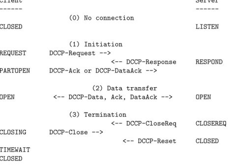
The DCCP draft [2] provides the following example of a DCCP connection:
Client Server --- ---(0) No connection CLOSED LISTEN (1) Initiation REQUEST DCCP-Request --> <-- DCCP-Response RESPOND PARTOPEN DCCP-Ack or DCCP-DataAck -->
(2) Data transfer
OPEN <-- DCCP-Data, Ack, DataAck --> OPEN (3) Termination <-- DCCP-CloseReq CLOSEREQ CLOSING DCCP-Close --> <-- DCCP-Reset CLOSED TIMEWAIT CLOSED
Figure 2.3: DCCP connection example
2.2
Congestion Control - TFRC and Variants
Congestion occurrence was first observed during the early stages of the Inter-net [9] and rate regulating algorithms for data connections were introduced by Jacobson [10] [11].
The assumption behind this early class of congestion response methods is that the Internet is a black box, in which congestion occurs from time to time and can be detected through packet drops. These algorithms rely on TCP retransmission and are therefore intended for transfers of bulk of data, where momentary rate decreases and delays due to retransmissions do not influence significantly the quality of service. More exactly, upon detecting congestion
through packet drops, TCP will halve the transmit rate and retransmit the affected packets.
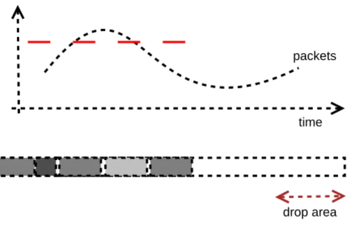
drop area time packets
Figure 2.4: Simple Drop-Tail Queue
For interactive applications, relying on the low latency of the received data, such a behavior is more problematic. Application developers would rather adopt a more conservative sending rate than start facing congestion through packet drops.
By contrast, a more modern class of congestion control methods tries to pre-empt the congestion behavior and has to take into account the particularities of the network devices involved in transmission and congestion control. Routers have to provide support for such congestion detection and avoidance techniques, and the transport layer protocols must act appropriately upon receiving a con-gestion notification. Some of these protocols use the IP layer for transporting congestion notifications, although this raises some problems in some environ-ments such as tunneled connections.
As discussed in [12] the typical router maintains a packet queue for all flows and drops only those packets for which the queue does not have available space, as illustrated in Figure 2.4. The result of this is that the queue can be for a long time in an almost filled size because flows might try to aggressively maintain a large data transmit rate and periodically overflow the queue. This behavior might seem fair; however we cannot ignore the importance of packet bursts in Internet data transmission. A burst of packets will need a significant part of the queue size, and if one of them will be dropped (very probable with a filled queue) the connection will have to back off.
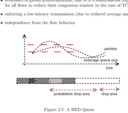
The RFC 2309 [12] presents the queue management algorithm Random Early Detection (RED) devised to overcome this shortcoming of simple rate control. RED divides the queue occupancy levels in thee zones:
• a safe zone, for which all packets are sent further
• a transition zone, for which packets are dropped probabilistically, with a probability depending linearly on the level of occupancy of this zone
The occupancy level of the queue (the average queue size) is computed using a an exponentially weighted low-pass filter which has the role of allowing bursts of traffic, since the average levels over time. The behavior of the RED queue is illustrated in Figure 2.5. Packets from the same burst (corresponding to the same flow) are more likely to receive the same marking, reducing thereby the number of different flows interrupted.
This congestion detection algorithm addresses the following issues in an ef-ficient way:
• allowing bursts of traffic
• avoidance of global synchronization, that is of a simultaneous requirement for all flows to reduce their congestion window in the case of TCP
• enforcing a low-latency transmission (due to reduced average queue size)
• independence from the flow behavior
drop area time packets
probabilistic drop area
avearage queue size
Figure 2.5: A RED Queue
Another problem RED and other congestion control methods face is the dif-ferent, possibly aggressive behavior of some flows (for example unregulated UDP flows). Algorithms which maintain different queues for different traffic classes or flows (CBQ or FQ) are necessary in this situation, otherwise a connection lock-out might occur (a monopolization of the queue by one certain flow). Un-der Linux, Generalized RED (GRED) provides such a differentiation of flows [13].
Note that fragmentation of datagrams does not cope well with some packet loss measurement techniques, since a packet loss translates into a whole data-gram loss.
Note: In order for it to function properly a RED queue’s parameters should probably be fixed after considering statistical data collected from monitoring the traffic through the respective router.
2.2.1
TCP Reno congestion control
Some of the widely deployed TCP implementations in the Internet are based on the 4.3BSD-Reno distribution, and its congestion control method is often referred to as TCP Reno congestion control.
TCP Reno’s transmission window sizeWregulates the rate of transmission. Initially the system starts with a default window size. As long as there is no indication of congestion, the window size is steadily increased with a factor of 1/W for each received acknowledgment. The receiver sends an acknowledg-ment for everyb packets received, where for most TCP implementationsb= 2. Therefore the rate of transmission increases linearly in time at a slope of 1/b, as illustrated in Figure 2.7.
The sender perceives packet loss either by the reception of “triple-duplicate” acknowledgments (four packets having the same sequence number) or via time-outs. In the presence of duplicate acknowledgments, the sender halves the trans-mit rate, while upon perceiving a timeout, the sender reduces the transtrans-mit rate to one packet per time T0, and if timeouts repeat, the retransmission time is
doubled up to a maximal value of 64T0.
sending timeout drop packet timeout/T=To packet timeout/T=2T triple duplicated ACK B=B/2 rate increase B = B+1/b
Figure 2.6: TCP-Reno states and actions
W To 2To 4To t drop drop timeout timeout timeout
Figure 2.7: TCP-Reno rate control as presented in [14]
Since any congestion-controlled protocol sharing a line with TCP flows is supposed to achieve TCP-fairness (i.e., to have a similar transfer rate over dif-ferent time intervals) difdif-ferent models that try to predict the rate achieved by
the Reno congestion control method under specific network conditions have been developed. At least one of these models has been investigated not only theoretically, but also compared with extensive observations of the behavior of connections between hosts situated at different distances on the Internet.
[15] presents a stochastic, Markov-based model of TCP-Reno’s behavior un-der a specific packet loss rate. Due to its complexity the complete model is suitable for simulation but does not seem to have a closed solution. However, under specific assumptions the author obtains an accurate formula for the data rate of a TCP connection: X(p) = s RT Tp2bp/3 +T0(3 p 3bp/8)p(1 + 32p2) where
• X is the transmit rate in bytes/second
• sis the packet size in bytes
• RT T is the round trip time in seconds
• pis the loss event rate, between 0 and 1, of the number of loss events as a fraction of the number of packets transmitted
• T0 is the TCP retransmission time in seconds
• bis the number of packets acknowledged by a single TCP acknowledgment The transmit rate cannot exceed the value Wmax
RT T whereWmax is the maximal TCP window size.
Note: TCP-SACK (TCP with selective acknowledgments) congestion control is becoming the more popular choice for congestion control in modern systems also due to the advance of wireless communication, in which occasional losses of packets are frequent but do not necessarily indicate congestion. The Linux and FreeBSD TCP stack implementations also deviate from the TCP-New Reno specification and implement TCP-SACK. For a detailed summary of the imple-mentation differences between 4.3BSD-Reno and the Linux stack please consult [16].
2.2.2
TCP Friendly Rate Control
RFC 3448 [17] describes TFRC, a congestion control method designed to pro-vided a smoother throughput of data more suited for multimedia applications. TFRC is further developed into a DCCP congestion control method in RFC 4342 [8]
TFRC uses the equation presented above in order to regulate its data through-put rate. The only parameters of the equation that must be estimated from measurements are the round trip time and the packet loss rate. Since RTT esti-mation is also common to TCP, in the following only the packet loss estiesti-mation process will be discussed.
Loss event rate measurement is performed at the receiver. Obtaining an accurate and stable measurement can assure that the transmit rate will not oscillate in a disruptive manner.
Assuming that all packets have unique sequence numbers, the receiver main-tains a data structure which keeps track of which packets arrived and which are still missing, and includes also the receiver timestamp for received packets. Loss is detected by the arrival of at least three packets with sequence number higher than the one of the expected packet. Successive losses occurring during the same RTT period are considered a single loss event.
The missing packets create a loss history which is in turn translated into a series of loss intervalsIn , describing the time elapsed between the observed packet losses. The last eight loss intervals are added together with weighting factors decreasing in order to favor the most recent measurements, giving an average valueImean:
Imean= 7 X i=0 wiIi wherewi= (1.0,1.0,1.0,1.0,8,0.6,0.4,0.2)
The most recent interval (the one having as upper bound the current time) is only taken into account if its presence would increase theImeanvalue. Finally the value pis computed as
p= 1
Imean
The same RFC describes a history discounting mechanism that changes the weights of the computed mean value when the most recent loss interval is more than twice as large as the computed average loss interval. This mechanism is designed to provide a more aggressive behavior in the absence of congestion.
Before the first loss event occurs, the sender finds itself into a so-called slow-start mode. The length of the first loss interval is approximated by reversing the rate equation, using the number of bytes received during the last RTT (X recv) before the initial loss occurrence as the left-hand side.
A DCCP stream operating under TFRC congestion control will face the following rate limitations:
• The transmission rate is upper bounded by X calc, the computed maximal transmission rate
• The transmission rate is upper bounded by 2∗X recv, the rate reported by the receiver through the last feedback packet; since feedback packets occur at most once per RTT, this assures that the transmission rate can at most double during one RTT.
• The transmission rate is lower bounded bys/R during the slowstart pe-riod, and bys/t mbiduring congestion avoidance, wheret mbi= 64s
2.2.3
TFRC for small packets
VoIP applications send small payload packets separated by fixed time intervals. [18] modifies the TFRC equation for dealing with this particular situation:
• the packet size s is fixed to 1500 bytes; TFRC streams sending small packets aim for achieving the same bandwidth utilization as a TCP stream using 1500 bytes-long segments.
• the send rate is multiplied by a factors true/(s true+H), with s true
denoting the average packet size and H the size of the packet headers (default value: 40 bytes).
2.2.4
Faster Restart for TFRC
VoIP application alternate periods of data sending with periods of idleness; at the beginning of a talkspurt, the application will try to reach the codec’s nominal rate as fast as possible; if the congestion control mechanism adapts too slowly and the rate limitations cause the send buffer to fill up, the application will experience packet losses.
As mentioned earlier, TFRC can only double the transmission rate during one RTT; [19] allows the transmission rate to quadruple, as long as the network has proven in the past that it can sustain the target transmission rate; for this purpose a variable X fast max records the maximal rate achieved by the sender during the last loss-free period. The network rate is quadrupled while remaining under X fast max and doubled afterwards. The value of X fast max will be halved after each loss event detection.
The second modification brought by the faster restart variant is the setting of the initial transmission rate after an idle period to eight packets per RTT.
The current implementation, used in this project, emulates the faster restart behavior by allowing the sender to quadruple the rate at all times, based on the assumption that the safe rate X fast max will stabilize around the codec’s nominal rate.
2.2.5
ECN Network Support
As mentioned earlier, packet dropping as a congestion notification method has the disadvantage of compromising the quality of service of certain applications, especially interactive ones, by disrupting the normal flow of data. For applica-tions willing to maintain conservative transmit rates in exchange for obtaining increased reliability, an early warning would be preferable. Explicit Network Congestion (ECN) addresses exactly this problem.
The ECN defining document [3] states that two bits of the IP protocol header should be used by the in-path routers in order to signal a potential congestion condition. The second bit serves the purpose of providing a ECN nonce holder, which, over a longer period of time, insures the fair behavior of the communi-cation partners.
The corrective action upon this notification is left to the transport protocol. Note that the ECN involves the intermediate routers (possibly using triggers similar to the ones coming from a RED queue), the IP protocol for carrying the notification and the nonce and the transport protocol for taking appropriate action.
RFC 3168 [3] describes some special implementation issues of the protocol, such as the fact that a congestion notification for a packet fragment at reassem-bly will trigger a congestion notification for the full packet, or that IP tunnels should mark embedded packets at decapsulation if congestion occurs during transport. Encrypted transports such as IPsec raise additional problems.
The success of ECN congestion control depends on its the degree of deploy-ment in the routers, especially those sitting at the edge of the network where
congestion is likely to occur. Since ECN offer the possibility of regulating traffic without quality disruptions, its advance is linked to the expansion of interactive applications.
The open-source operating systems FreeBSD and Linux as well as the major vendors for routers have added ECN support. It is up to the system adminis-trators to use this option properly for offering improved performance.
2.3
DCCP Mechanisms Implementation
The current section presents the DCCP implementation used in the experiments, and gives an overview of two of the proposed protocol APIs. The first API is based on shared memory zones between the kernel and the application, tries to achieve high performance and offers the possibility of late decision on the actual packets to be sent. The second API is based on the classic sockets interface, minimizing the complexity of porting applications to the new protocol.
2.3.1
The KAME implementation
The FreeBSD KAME kernel includes a DCCP protocol implementation based on the Lulea University DCCP for FreeBSD project [20]. This implementation is maintained by Yoshifumi Nishida.
The code implements currently most of the core DCCP functionality, includ-ing feature negotiation, and has a modular design which allows the addition of different CCID modules.
The implementation supports currently CCID 3 (TFRC), intended mainly for multimedia applications. The VoIP variant of CCID 3 will follow.
A number of networking tools have been patched to support the new protocol under this implementation (the socket API for DCCP is not yet standardized). These applications include:tcpdump, ethereal, iperf, netcat.
We have developed a ttcp clone, named kttcp, capable of reading framed data from the standard input and sending it over TCP, UDP or one of the DCCP congestion control modes to another endpoint of the network, where it will be printed on the standard output. The application is capable of gathering packet statistics.
The DCCP implementation has been extended during this project for sup-porting TFRC for small packets, TFRC for small packets with faster restart, and a modified version of the faster variant method. In order to comply with the requirements of interactive media traffic transmission, a sysctl handle for adjusting the size of the send buffer has been added.
2.3.2
The Packet-Ring socket API
Eddie Kohler and Junwen Lai have proposed a novel API for managing the transmission of unreliable datagrams using DCCP [21]. The API has as its strong-points high throughput, kernel-enforced congestion control and late data choice, i.e. the application can commit to sending a piece of data very late in the data sending process. The constructive design of the API encourages appli-cations to assign priorities to the packets constructed and, in case congestion is detected, select the most important ones for transmission. This approach
matches the design of most modern codecs, for which certain frames (for exam-ple synchronization frames) have a much larger qualitative impact than others. The classical sendmsg() API allows the kernel to perform buffering of packets to be sent, and such buffering is likely to occur under congestion. Applications might want to exchange this increase in reliability for timeliness of the delivery. The solution proposed as an alternative is using apacket ringdata structure, stored in memory shared by the application and the kernel, in a manner similar to DMA rings. The application queues packets for transmission by placing them at the end of the packet ring, transparent to the kernel.
For communication between the kernel and the application, four pointer variables are available: dev i, kern i, umod i, user i. Their relative order is fixed, and the kernel has control overdev iandkern iwhile the application has control over umod i and user i. umod i marks the limit between the packets that the kernel can send and the ones that the application can still modify.
dev_i kern_i umod_i user_i
Figure 2.8: Packet ring
The benefits of using this API are double: not only does the application achieve faster transmission of datagrams, but in case of congestion the more important datagrams have a higher chance of making it through.
One could further develop this idea into a sendmsg()-like transmission func-tion having a priority parameter for allowing the selecfunc-tion of packets to be trans-mitted in case of congestion. In this way the changes to the existing codebase currently running on top of UDP would be minimal.
2.3.3
User-space implementation specifics
An user-space application willing to use the DCCP protocol as its transport can invoke it through an adapted socket API. The steps to be taken for opening and using a DCCP connection are the following:
• Filling out a hosthints structure(client). The hosthints structure to be used by getaddrinfo() for a client must be filled with the values
ai socktype = SOCK CONN DGRAM and ai protocol = IPPROTO DCCP.
• Setting the hostflags to AI PASSIVE (server).
• Calling the getaddrinfo() function(client).
Note: The getaddrinfo() function does not yet support DCCP hints.
• Initializing a socket. The socket() call uses the hostinfo structure filled by getaddrinfo()
• Binding the socket (client)
• Setting the CCID
• Setting the maximum segment size option
int buflen; setsockopt(fd, IPPROTO DCCP, DCCP MAXSEG, &buflen, sizeof(buflen))
• Setting the DCCP service option. The role DCCP service option is anal-ogous to the one of a port for a UDP or TCP socket. setsockopt(fd, IP-PROTO DCCP, DCCP SERVICE, dccp services, dccp services nr * sizeof(int))
• Create a connection(client). Since DCCP is connection-oriented, the con-nect() function call has been extended for DCCP.
connect(fd, const struct sockaddr *name, socklen t namelen)
• Listen for a connection and accept incoming connections (server).
listen(fd, 0)
fd = accept(fd, struct sockaddr * restrict addr, socklen t * restrict addrlen)
• Write to the socket or read from it. The send() and recv() system calls allow writing to or reading from the socket.
• Close the socket. The socket should be closed using close(fd)
The current chapter presented the DCCP protocol, its currently proposed congestion control methods, and details of their implementations.
Chapter 3
The Impact of DCCP on
VoIP
The current chapter addresses some of the issues appearing when sending VoIP traffic over a congestion-aware protocol. It continues by giving an overview of the assessment methods of the perceived quality of voice transmission, also in the context of packet-switched networks. The chapter discusses some statistical properties of voice streams that might be used in trying to optimize the quality of the transmission. Finally, some strategies for dealing with congestion build-up in the case of variable rate codecs are presented.
3.1
Strategies for VoIP DCCP Applications
The draft [22] presents some of the problems that applications using DCCP for VoIP telephony face. These problems originate in the following requirements of VoIP services:
• Low latency: VoIP applications should have an end-to-end latency of less than 150ms in order to present the user with a feeling of interac-tivity. Users are accustomed to such delays from using the normal circuit-switched phone service. While the latency is mainly generated by the network’s behavior, an efficient strategy for VoIP applications should not increase it, nor should it add to it the problem of jitter (variations of the packet latency being perceived by the receiving user).
• Fast start: VoIP applications are based on codecs which usually have a minimal required transmit rate. However, starting the transmission of a stream with a somehow large byte rate does not fulfill the principles of congestion control. Applications will probably have to cope with an initial slow-start period.
• Silence suppression: Most modern codecs use silence detection mecha-nisms and stop sending data packets when silence is detected, saving ac-cording to measurements up to 70% of the available bandwidth. While this change is quite steep for the codec generated data, when the codec starts transmitting again the bandwidth increase will be again gradual
(see the previously discussed fast start problem). The alternatives dis-cussed on the DCCP mailing list are: sending packets of varying size at a constant rate with padding as content and using artificially generated noise for forcing the codec to generate data continuously.
• Bandwidth variation: This problem, while similar to the one discussed just before, is more likely to appear in combination with video codecs generated streams, and the problems that it poses are harder to solve than in the previous case.
A video codec can generate compressed frame data by calculating the differences between successive frames. While between some frames these differences are small, a change of the scenery for example can require a so-called synchronization frame, generating additional data. According to [22] these rate changes can have a relative factor of ten for example, and can occur from one packet sent to another one, leaving a rate-controlling strategy practically no time to adjust. Buffering-averaging methods could be used for smoothing this fast increase, however they might contribute to a depreciation of the quality of service perceived by the user. While the factor of change for pure VoIP applications is such that the current rate control strategy could adapt to it, one should consider the advance of voice transmissions when designing a comprehensive strategy.
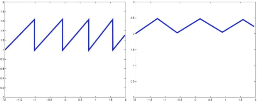
RFC 3448 [17] defines the TCP-Friendly Rate Control (TFRC) an alternative to the TCP rate control method defined in RFC 2581 [11]. While TCP rate control uses the Additive Increase Multiplicative Decrease (AIMD) method, TFRC has a smooth response to packet loss.
Figure 3.1: TCP vs. TFRC rate control
It can be assumed, for an increase of generality that the application can use a few nominal connection rates for sending data, resulting in different perceived quality. This assumption gives more flexibility in constructing an appropriate strategy.
In order to deal with the problems described above, the following strategy has been proposed (Strategy 3 in the original document [22]):
• Startup rate increase: The connection setup should include an initial rate increase phase in which no actual voice communication takes place. After
the initial connection establishment (for example through SIP messaging) the two parties exchange idle data in order to achieve an appropriate rate for beginning voice transmission. If this rate is not achieved within a reasonable amount of time, the connection is interrupted and the call is cleared.
• Congestion compensation: If congestion occurs during a call, TFRC will reduce the sending rate, and the application can switch to a lower rate codec. However, the application should pad its transmission to the allowed TFRC rate, in order to determine TFRC to increase the sending rate such as to allow the return to a higher-rate codec. This padding is only necessary if the rate increase is desired.
• Playout buffer: A playout buffer of about 100 ms can reduce the jitter experienced by the end-user.
The TFRC-VoIP mode comes to address further issues. This special TFRC mode addresses applications using small-sized, frequently transmitted frames in order to improve interactivity. According to the original document [22], usual voice packet data sizes are 80 to 320 bytes, well-under the 1480 bytes MTU of typical IP packets.
This can lead to problems, since while some network limitations are in bytes per second, others (the ones originating in routers for example) might be in packets per second, giving a DCCP stream less bandwidth than the one allocated to a comparable TCP stream. The VoIP mode of TFRC is designed to address such difficulties in applications using a transmission interval of at least 10 msec between packets.
3.2
Factors affecting VoIP transmission quality
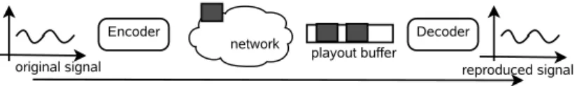
A typical VoIP application takes sampled and digitized equal-length intervals of an audio signal which it compresses using a specialized codec, packetizes it and sends it over the network. The receiver de-packetizes the data and places it in a playout buffer, which has the role of compensating for the jitter that occurs during transmission. The data is then decompressed and the voice signal is replayed.
The sensible points influencing the perceived quality of the output signal are the codec performance, depending also on the bandwidth usage, the amount of networks loss, which can be to a point compensated by packet loss conceal-ment methods, the network delay as well as the overall measured delay and the network jitter (the variance of the network delay). From the factors mentioned above, the network loss, network delay and jitter pertain to the underlaying net-work and can be traced back to congestion situations, queuing strategies and congestion control strategies while the other factors are application specific. Jit-ter, for example, depends heavily on the intermediate router’s queuing behavior and the presence of alternative routes between the endpoints.
On the application side, VoIP applications use adaptive playout buffers in order to compensate for the jitter effect. Usually periods of silence are used for adapting the buffer’s size. Moon, Kurose and Towsley present strategies that can be used by applications in order to compensate for network jitter using adaptive playout buffers, and give bounds on their possible performance [23].
Figure 3.2: VoIP transmission sequence
3.3
Perceived quality models
The interest in the assessment of end-to-end perceived quality of voice streams has first appeared in the research of the telephony companies. Algorithms for the qualitative evaluation of the transmitted signals relay on psychoacoustic models, and due to their high complexity usually are applied on offline data samples which are compared to the original ones.
Generally the measurement unit for the perceptual quality of a voice trans-mission is the Mean Opinion Score (MOS), a subjective quality score ranging from 1 (unacceptable) to 5 (excellent). These scores can be computed by using subjective test or by analyzing the system using an objective model. For exam-ple, the PESQ algorithm generates quality scores which correlate well with sub-jective tests. The E-Model provides another way for generating quality scores and is particularly suited to assessing the distortions which appear due to packet transmission processes.
3.3.1
PESQ
The International Telecommunication Union (ITU) has developed the PESQ algorithm as Recommendation P.862. PESQ is able to predict perceived quality in a very wide range of conditions, including coding distortions, errors, noise, filtering, delay and jitter. The techniques used by the PESQ algorithm are documented in a series of articles by its authors. [24] [25]
The first problem that PESQ tries to solve is the detection of constant delay and jitter in the output sample. The algorithm does not use classical transfer function estimation or windowed cross-correlation techniques, but introduces a histogram-based technique.
The reference and measured signals are filtered through a high-pass filter during pre-processing. The motivation of this action is that while most of the typical speaker’s voice signal’s energy is concentrated in the low-band (under 500 MHz) the components of the voice spectrum that influence the intelligibility of the signal lie in the high-band.
A first approximation of the delay is given by the maximal cross-correlation point of signal envelopes, 4-ms long nonoverlapping signal frames. Due to the fact that the signal is highly nonstationary at this time scale, this indication is likely to be quite precise. The approximated delay is afterwards eliminated from one of the signals through a time shift.
In what follows the signals are divided into 64-ms 75%-overlapping frames and the position of the maximal cross-correlation is computed for each frame. The frame delays are then weighted according to their loudness and a running
average of these is the first estimate of the actual delay. This running value is smoothed by convolution with a triangular filter, obtaining the delay estimate. In packet-switched networks jitter is more common than constant delays. Therefore the above-mentioned technique has been extended for the detection of jitter by using different frame types. The underlying assumption of the al-gorithm in this situation is that in the audio data corresponding to a certain transmitted packet the jitter is constant.
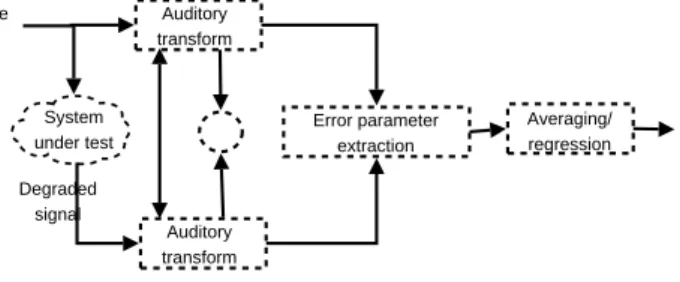
The paper [26] describes the PESQ algorithm in more detail, with an em-phasis on its quality computation technique. In PESQ the audio signals are transformed into a psychoacoustical model representation, which in this case is calculated on the basis of signal representations that use the psychophysi-cal equivalents of frequency and loudness. The difference between the internal representations of the input and the delay-compensated output represents the audible difference of the two samples, which will in turn be used to predict the perceived quality degradation.
Auditory transform Auditory transform Error parameter extraction Averaging/ regression Prediction of perceived quality System under test Degraded signal Reference signal
Figure 3.3: PESQ algorithm assessment cycle
The first step of the quality measurement is the calibration of the output signal for eliminating gain both in time domain and frequency domain by using test signals. The resulting signal filtered in order to simulate the effects of a headset on the output signal and its active speech part is isolated. In order to simulate the time-frequency decomposition performed by the human ear, a short-term FFT is applied to a window of 32-ms frames, overlapping in a proportion of 50%, obtaining the power spectra of the original and degraded signals. Effects that do not influence the psycho-acoustical perception, such as linear gain or short time-varying gain are compensated. Afterwards the so-called loudness density is computed, an indicator whose difference between the original and degraded signal is used for calculating the disturbance density, which shows the effects of noise on the signal.
The above-mentioned and other indicators have been correlated with the re-sults of qualitative measurements performed by human subjects in order to train it for independent usage. The trained PESQ algorithm has a correlation rate of 0.935 with the human tests, making it a highly reliable quality measurement technique.
While the PESQ algorithm is particularly well-suited for assessing the distor-tions of the sound during transmission over a line which induces signal changes, it was not designed for the realm of digital, packet-switched networks. Its com-plexity makes it unsuitable for online quality comparison, and the final quality
score that it provides is dependent heavily on factors such as codec character-istics, and in order to infer the exact effect of the network state parameters on the quality score of the received signal further analysis will be required.
Given a time series representing packet end-to-end times or loss marks, we would like to be able to estimate the perceived quality of the corresponding voice transmission.
The preferred scale for classifying the perceived quality of a voice connection is the mean opinion score (MOS), used in subjective quality evaluation tests, and ranging on a scale from 1 (unacceptable) to 5 (best).
The International Telecommunication Union (ITU) has published the PESQ algorithm as Recommendation P.862. PESQ is able to predict perceived quality in a very wide range of conditions, including coding distortions, errors, noise, filtering, delay and variable delay (jitter). The techniques used by the PESQ algorithm are documented in a series of articles by its authors. [24] [25]
3.3.2
E-Model
The ITU-T E-Model [27] is an online analysis method generating a MOS score. The E-Model defines a quality factorR, from which heM OS score is obtained through the equation:
M OS= 1 + 0.035R+ 7∗10−6R(R−60)(100−R) illustrated in Figure 3.4
The authors have emulated the speech quality evaluation process of PESQ in measuring the quality degradation due to individual frame losses and have formulated a theoretical model for both distant and burst losses. In the case of burst losses correlation effects leading to increased perceptual distortion had to be accounted for. 0.5 1 1.5 2 2.5 3 3.5 4 4.5 0 20 40 60 80 100 MOS score R factor 1+0.035*x+7*0.000001*x*(x-60)*(100-x)
Figure 3.4: R factor - MOS score relationship
The E-Model has been further simplified [28] [29] for approximating the quality of VoIP-transported conversations. Their model approximations are capable, for the different codecs considered, to offer a quality statistic starting from the series of delays and losses associated with packet transmission. In the following chapter the E-Model based evaluation methods for packetized audio transmission will be presented in the form of a quality metric.
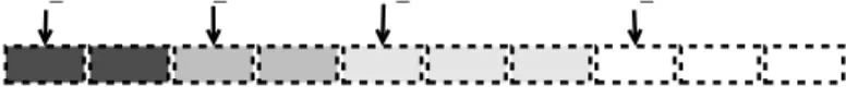
Figure 3.5: Distribution of the packet importances [30]
3.4
Statistical Properties of Voice Streams
Hoene, Wiethoelter and Wollisz [30] have used the PESQ analysis method in order to study the impact of different types of packet drop sequences upon the perceived speech quality. They compared the difference between the original audio streams and the streams decoded in the absence of individual frames. The result of their MOS measurements for an 8s long sample with a varying starting position and content of the dropped packet is shown in the figure 3.5:
The authors introduce a metric for the importance of the individual frame. LetM OS(s) be the MOS score of sample with no packet drop, M OS(s, e) be the MOS score under packet loss, with e being a vector describing the packet losses andt(s) be the length of the respective sample. The importanceImp(s, e) is defined as:
Imp(s, e) = (M OS(s)−M OS(s, e))t(s)
The above figure shows that the importance of most frames is relatively negligible.
The authors have emulated the speech quality evaluation process of PESQ in measuring the quality degradation due to individual frame losses and have formulated a theoretical model for both distant and burst losses. In the case of burst losses correlation effects leading to increased perceptual distortion had to be accounted for.
As online evaluation algorithms for evaluating the importance of different speech packets emerge, discriminative drop of packets might help increase the quality of the arriving signal. This idea is again approached in a following section.
3.5
Optimizing the Perceived Quality
As previously noted, streaming media packets have a largely varying impact on the quality of the re-combined signal. For example, statistical measurements show that few encoded speech packets have a high importance and standards
such as JPEG use synchronization frames which influence a longer series of packets.
The congestion prevention characteristics of DCCP make it possible to select before the actual transmission which packets should be dropped from the out-going queue and allows the regulation of the queue’s behavior through a series of informed decisions. While, upon congestion notification, DCCP could inform the application of the new data transmission rate and request that the outgoing data be replaced with data encoded at this rate, it seems far-fetched to assume that an application could react in all cases appropriately fast. However, assum-ing that the outgoassum-ing queue’s de facto rate is larger than the current transmit rate, and that the application is interested in the timely transmission of data, it is likely that the kernel will have to decide which packets should be transmitted and which packets should be dropped.
We propose, therefore, an extension to the classic packet sending API, allow-ing an application to inform the kernel of the pre-computed importance factor of a given packet. This information could be sent either as an extra parame-ter of the send function, or as ancillary data associated with DCCP packets. The second information needed for applying this behavior is a time-stamp on the outgoing packets, allowing the kernel to decide on their expiration moment. The kernel might apply this timestamp during the execution of the write() call. The kernel strategy would be to select the combination of packets for trans-mission that, by accumulating their individual importances, maximize the total importance and can be sent, at the momentary data rate, without exceeding the expiration time of any of the packets included. Given that each packet has an importance(gain) and a size factor(weight), this problem is an instance of the well-known backpack problem.
3.6
Adaptive Codecs
Speech compression codecs for voice produce a stream of equally time-spaced packets with their size varying depending on the amount of audio information to be transmitted. This behavior is implemented using the so-called variable bit rate (VBR) compression technique. Moreover, in periods when silence sup-pression is active the codec can completely stop encoding. Therefore, a certain variation of the bandwidth usage over time is to be expected, and since the application has an interactive nature, requiring timely delivery of packets, this variation must be permitted.
The same speech compression provide often an option for setting the target average bit rate (ABR), which the codec is supposed to target when performing VBR encoding. Applications can choose an encoding rate appropriate for the available bandwidth, adverting packet loss, or can decide to drop the connection if a minimal bandwidth is not available. The quality decrease due to a lower bandwidth should be more acceptable than the one due to packet drops.
The application should be able to detect the admitted transmission rate. Two methods are available:
• Reading through the socket API the data necessary for computing the instantaneous transmit rate. It appears that at this moment the API does not report the whole set of data needed for such an operation: while
high rate encoder low rate encoder
Figure 3.6: After congestion is detected, the high quality packets are replaced with smaller, lower quality packets which have a higher chance of arriving at the destination.
the transmission window size is available, the RTT measured value is also necessary.
• Measuring the delay induced by write() calls, and trying to approximate the transmit rate from it. This method is less precise since it involves user-space measurements, however, its accuracy might suffice for this purpose. Based on this measurement, an application can instruct the codec to modify the ABR for future packets, or, since voice encoding is a from a computational perspective relatively inexpensive, decide to re-encode those packets still await-ing to be sent (if an API such as the previously described packet-buffers is used). Moreover, if the application experiences a sudden drop of the transmit rate, it can choose to remove from the queue those packets which will be least missed qualitatively in the voice signal’s reconstruction.
The current chapter addressed some of the issues appearing when sending VoIP traffic over a congestion-aware protocol. It continued by giving an overview of the assessment methods of the perceived quality of voice transmission, also in the context of packet-switched networks and discussed some statistical prop-erties of voice streams that might be used in trying to optimize the quality of the transmission. Strategies for dealing with congestion build-up in the case of variable rate codecs were presented.
Chapter 4
Evaluating VoIP Quality
The current chapter presents the experimental setup and the metrics involved in the quality evaluations. The chapter begins with a description of the conver-sation model used for generating speech patterns, followed by the presentation of the metric used in evaluating the way in which packet transmission reflects in voice quality. Next, it presents an algorithm for bounding the performance of playout buffers, adapted for fitting the quality estimation requirements. In the end it introduces the experimental setup used.
4.1
Generating Conversation-Like Data
Sriram and Whitt [31] introduce an on/off model for conversational patterns, in which periods of voice activity of variable length alternate with periods of silence. In the current approximation of the model we have generated, using exponential distributions, periods of voice activity of 1 second average duration, followed by periods of silence of 1.5 seconds average duration.
The input audio sequence is obtained by concatenating periods of continuous speech with periods of silence. The resulting audio is processed through the Speex audio codec for performing voice activity detection, and the resulting audio frames sequence is padded and packetized in order to emulate either the G729 or the G711 codec.
A segment of the resulting speech pattern is illustrated in Figure 4.1.
Figure 4.1: Resulting speech pattern
4.2
A Metric for Quality
The ITU-T E-Model [27] is an online analysis method generating a MOS score. The E-Model defines a quality factorR, ranging from 1 to 100 as:
R=R0−Is−Ie−Id+A where the subfactors have the following meanings:
• R0 - the effects of noises
• Is - the effects of impairment occurring simultaneously with the voice signal
• Ie - the effects of impairment caused by losses
• Id - the effects of impairment caused by delay
• A- compensates for the above impairments under certain conditions TheM OS score is obtained through the equation:
M OS= 1 + 0.035R+ 7∗10−6R(R−60)(100−R)
In a VoIP system, due to the fact that delays and losses are the main affecting factors, the factorsId and Ieare the only variables left. Cole and Rosenbluth have reduced the model to the following equation, using appropriately chosen default values for the canceled factors:
R= 94.2−Ie−Id
Their tests have shown that the following defining relation forIecan be used in estimating the impact of loss:
Ie=λ1+λ2ln(1 +λ3e)
where λ1 quantifies the voice quality degradation due to the codec, λ2 andλ3
refer to the degradation due to loss and e represents the overall packet loss rate. Values for theλparameters have been determined through simulations of different loss conditions for different codecs, and are reproduced in the Table 4.1 as published in [29] and [28].
Table 4.1: Coefficients for the calculation of the quality impairment due to loss [29] [28]
Codec frames / pkt λ1 λ2 λ3
G.711 1 0 30 15
G.729 1 10 47.82 18 G.729A + VAD 2 11 30.00 16
Similarly the impact of delay has been modeled [28] as:
Table 4.2: Interpreting R factors and MOS scores[28] R MOS Quality 90 - 100 4.34 - 4.5 Best 80 - 90 4.03 - 4.34 High 70 - 80 3.60 - 4.03 Medium 60 - 70 3.10 - 3.60 Low 50 - 60 2.58 - 3.10 Poor
where I(x) is a unity step function and d is the total end-to-end delay. The form of this equation is justified by the experimental observation that after a threshold calculated at 177.3ms delays lead to a faster perceptual degradation.
The same authors interpret the MOS scores as indicated in Table 4.2. The R factor under different loss and delay conditions is illustrated in Figure 4.2 for the G729 and G711 codecs.
1e-04 0.001 0.01 0.1 0 100 200 300 400 0 25 50 75 100 R G729 loss delay (ms) R 1e-04 0.001 0.01 0.1 0 100 200 300 400 0 25 50 75 100 R G711 loss delay (ms) R
Figure 4.2: R factor variation under delay and loss conditions for the G729 and G711 codecs
4.3
Playout Buffer Performance Bounds
Cohen [32] was the first to mention the effect of jitter on audio packets traversing multiple networks.
Packets arriving at the receiver suffer different delays in the network. In order to provide a quality listening experience an audio application will try to replay them with a relative delay corresponding to their sampling period.
Arriving packets will be placed in a so-called playout buffer and delayed in order to achieve the same end-to-end delay for almost all/all packets within a talkspurt. Packets that cannot be played within this bound will be silently dropped.
Figure 4.3 gives a graphical depiction of the playout-buffer’s operation. For each talkspurt a buffer management algorithm fixes a certain target delay (the elevation of a line of slope 1 separating the played packets from the packets silently dropped). The figure suggests that adjusting this value brings along a compromise between end-to-end delay and the loss percentage of the connection. Different online management algorithms have been researched, published and are in usage in current applications (see [33], [23]), and the field is un-dergoing further research. Some of these algorithms have specific assumptions about the distributions of packet delays, for example they might be designed in order to cope with bursts of packets resulting from a congestion-relieved router. Currently, no buffer management method can be considered a standard, and different methods offer quite different delay/loss exchange rates.
For the purpose of evaluating the quality of packetized audio connections, some authors have proposed applying offline bounds on the performance of play-out buffer management techniques. Rosenbluth and Cole [28] fix the end-to-end delay for the entire length of the conversation, and obtain their delay value by applying a Chernov bound on the arrival distribution. Tao and Guerin [34] de-fine their fixed delay value asarg max(R(d)), whereR(d) is the quality function described in the previous section, applied on the series of packets resulting after selectingdas a maximal end-to-end delay threshold.
Assuming that the delays induced by the transport layer’s congestion control mechanism might be unevenly distributed, using the same target delay for the entire conversation becomes inappropriate. A tight bound on the performance requires that every talkspurt, considered a minimal unit for which all packets must have the same end-to-end delay, be assigned its individually computed delay.
send time arrival time
loss delay
Moon, Kurose and Towsley have introduced [23] an algorithm based on dy-namic programming for computing the minimal delay of each talkspurt, assum-ing a maximum number of admissible losses caused by the output buffer in the whole conversational pattern. In the following we introduce their notation and give an overview of their method:
Let a trace consist ofN packets grouped inM talkspurts. Define:
• nk the total number of packets in thek-th talkspurt
• ti
k, sender timestamp of the i-th packet in thek-th talkspurt.
• aik, receiver timestamp of thei-th packet in thek-th talkspurt.
• dik the normalized delay of thei−thpacket in thek-th talkspurt; the nor-malized delay is the packet network delayaik−tik from which the minimal packet network delay in the talkspurt has been deducted
• d(ki) is thei-th smallest normalized delay in the k-th talkspurt
• D(k, i) the minimum average delay possible when choosing i packets to be played from thek-th toM-th talkspurt
Assuming that the packets in the different talkspurts cannot collide when played out as a result of delays, the authors derive the following equation:
D(k, i) = 0 ifi= 0 d(ki) ifk=M andi≤nM ∞ifk=M andi > nM min0≤j≤i ((i−j)D(k+ 1, i−j) +jd(kj))/i, otherwise
The valuesD(0, i), the minimal average delays of the entire connection, cor-responding to different packet loss rates in the playout buffer, can be computed in O(M ·N2) time.
Knowing that each delaydhas a corresponding impairmentId, the method presented above can be modified in order to obtain a minimal averaged delay impairment (minimizing the valueD(0, i) does not automatically minimize the corresponding averaged Id, due to the non-linearity of the delay impairment function). LetId(k, i) be the minimum average delay impairment possible when choosingipackets to be played from thek-th toM-th talkspurt.
Id(k, i) = 0 ifi= 0 Id(i) k ifk=M andi≤nM ∞ifk=M andi > nM min0≤j≤i ((i−j)Id(k+ 1, i−j) +jId(j) k )/i, otherwise
For eachi, after taking into account the network and sender losses, a corre-sponding loss impairmentIl(i) is obtained. Denoting: R(i) = 94.2−Id(0, i)− Il(i), chooseR=R(i), wherei=arg maxiR(i) to be the upper bound on the audio quality of the trace.
Note: In the previously presented algorithm for estimating the best playout buffer decision it is assumed that all packets have a similar impact on the per-ceived quality. However, this might not be the case and algorithms based on more advanced quality measures might take a better-informed decision. For the E-Model based metric, the choice of dropped packets is not important.
4.4
Experimental Setup
The network setup is illustrated in Figure 4.4. It consists of three source ma-chines, one router machine and one machine acting as a sink. The three sources are switched together to the same interface of the router;
Figure 4.4: Network topology
Each one of the three sources is running four encoder processes, simulating the start point of an uni-directional voice connection (a DCCP half-connection). Different network conditions are simulated by applying dummynet rules [35] on the router’s outgoing interface. The experiments vary either the network delay between 0 and 400 ms, or the network loss ratio between 0.001% and 0.1%, present in both directions of the connection. The losses are uniformly distributed over time. We did not employ any models of Internet-specific or congestion-specific loss patterns, for example burst losses, since TFRC’s loss interval approximation algorithms should be robust to such patterns.
The incoming interface of the router uses a 50 packet-long FIFO drop-tail buffer; for the multiple-connection experiments the buffer is bandwidth limited in order to cause apparent congestion.
The sender and the receiver track all codec frames. The sender logs all frames considered for sending before the send system call. The receiver logs all incoming frames after the completion of the recv system call. Further logging is performed by the router on the incoming and outgoing interfaces, using libpcap. The current chapter presented the experimental setup and the metrics in-volved in the quality evaluations. The chapter gave a description of the conver-sation model used for generating speech patterns, followed by the presentation of the metric used in evaluating the way in which packet transmission reflects in voice quality. It presented an algorithm for bounding the performance of playout buffers, adapted for fitting the quality estimation requirements. In the end it introduced the experimental setup used.
Chapter 5
Experimental Results
This chapter presents the experimental results obtained and gives a discussion of DCCP’s behavior in comparison to UDP and TCP.
5.1
Results
In contrast to TCP applications, UDP applications do not use a socket buffer in order to regulate the flow of data sent through the network, as packets written tend to be sent out immediately. For interactive applications the usage of a send buffer is unusual; however, for congestion control capable protocols, the application might prefer delaying the packets for small amounts of time instead of dropping them due to the momentary impossibility to send. Especially for applications that vary the rate of the data transmitted through the network by adjusting the packet size or stopping transmission frequently, such provi-sions might help in avoiding unnecessary packet loss during the time needed for probing for available bandwidth.
The KAME implementation has been modified during the project in order to allow the usage of a send buffer of configurable size. For the current experiments, the buffer size was set to a maximum of five packets, causing a maximal delay of 100 ms in the case of a 20 ms sampling rate.
The different DCCP congestion control modes have been compared to UDP, TCP using an increased initial window as specified in RFC 3390 [36] and TCP using the smaller initial window specified in RFC 2581 [11]. For the TCP transmission the TCP NODELAY socket option was used in order to disable Nagle’s algorithm for concatenating small buffer messages [9].
The following notations are used in the quality plots:
• UDP: The UDP Protocol
• TCP: The TCP Protocol, with the modification described in RFC 3390 enabled
• TFRC: TCP friendly rate control
• TFRC SP: TFRC small packets variant
• TFRC SP FR: TFRC small packets variant, with faster restart
• TFRC SP FR MD: TFRC small packets variant, with faster restart, modified in order to never decrease the sending rate below eight small packets per RTT; the minimal sending rate is computed as8(s+RH) wheres
is the average packet size,H is the packet header size, defaulted according to [18] to 40 bytes, andRis the RTT estimate.
Varying Delay - The first series of experiments varied the one-way delay of the connection between 25 and 400 msec. Due to the absence of losses, in this series of experiments, TFRC works only in the slowstart mode. For this reason, the faster restart variant of TFRC for small packets does not show a more aggressive response function than TFRC for small packets , since both variants specify that the transmission rate can at most double during one RTT in the slow start period.
The sending rate after periods of idleness was found to suffer due to a desyn-chronization between the idleness detection mechanism and the feedback mech-anism, which reports the received rate X recv. The reasons leading to this effect are discussed in the Section 5.2. We note that the TFRC SP FR MD version was not allowed to decrease the transmission rate under eight packets per RTT, despite the reported X recv rate.
The effects can be observed in the Figures 5.1 a), 5.1 b) and 5.1 c), which show a sharp decrease of the quality score once the delay increases. The
![Figure 2.1: DCCP - a generic header and an acknowledgment [5].The packet formats are described by the DCCP draft.](https://thumb-us.123doks.com/thumbv2/123dok_us/781778.2598864/9.892.314.577.193.266/figure-dccp-generic-header-acknowledgment-packet-formats-described.webp)
![Figure 2.2: DCCP State Diagram [6]](https://thumb-us.123doks.com/thumbv2/123dok_us/781778.2598864/10.892.290.594.346.833/figure-dccp-state-diagram.webp)
![Figure 2.7: TCP-Reno rate control as presented in [14]](https://thumb-us.123doks.com/thumbv2/123dok_us/781778.2598864/14.892.279.624.790.903/figure-tcp-reno-rate-control-as-presented-in.webp)