A cooperative perception system for multiple UAVs: Application to automatic
detection of forest fires
Luis Merino1, Fernando Caballero2, J. R. Martínez-de Dios2, Joaquín Ferruz2 and Aníbal Ollero2 Robotics, Vision and Intelligent Control Group
1Dpt. Environmental Sciences, Pablo de Olavide University, Seville, Spain 2Dpt. Systems Engineering and Automatic Control, University of Seville, Seville, Spain ABSTRACT: This paper presents a cooperative perception system for multiple heterogeneous UAVs. It considers different kind of sensors: infrared and visual cameras and fire detectors. The system is based on a set of multipurpose low-level image-processing functions including segmentation, stabilization of sequences of images and geo-referencing, and it also involves data fusion algorithms for cooperative perception. It has been tested in field experiments that pursued autonomous multi-UAV cooperative detection, monitoring and measurement of forest fires. This paper presents the overall architecture of the perception system, describes some of the implemented cooperative perception techniques and shows experimental results on automatic forest fire detection and localization with cooperating UAVs.
KEYWORDS: multi-UAV system, cooperative perception, automatic forest fire detection, field experimentation.
1. Introduction
In the last decade unmanned aerial vehicles (UAVs) have attracted a significant interest in many field robotics applications. The higher mobility and maneuverability of UAVs respect to ground vehicles have made aerial vehicles the natural way to approach a target to get information or even to perform some actions such as the deployment of instrumentation. Aerial robotics seems a useful approach to perform tasks such as data and image acquisition of targets and areas inaccessible using ground means, localization of targets, tracking, map building and others. UAVs have been widely used for military applications but, recently they are being extended to civilian applications such as natural and human made disasters scenarios, search and rescue, law enforcement, aerial mapping, traffic surveillance, inspection and cinematography (Ollero & Merino, 2004).
Many of these applications require robust and flexible perception systems. The most common perception devices in UAVs are cameras and range sensors. Range sensors are used for some specific operations such as autonomous landing and mapping (Miller & Amidi, 1998). Computer vision plays the most important role and has been applied for different tasks. It has been used as a method to sense relative position, as in the approach by Omidi, Kanade & Fujita (1999), where it is implemented the concept of visual odometer, in Zhang & Hintz (1995), where a video-based attitude and height sensor for low altitude aerial vehicles is presented, or in Corke, Sikka & Roberts (2001), where a stereo vision system is used for height estimation. Vision-based methods have been also considered for safe landing of a helicopter (Saripalli, Montgomery & Sukhatme, 2003). Lacroix, Jung & Mallet (2001) describe Simultaneous Localization and Mapping (SLAM) techniques with stereo vision systems on board an autonomous airship. UAV SLAM with vision is also presented in Kim & Sukkarieh (2003).
Furthermore, computer vision has been used for detection and monitoring. Thus, algorithms for dense motion estimation have been applied to traffic monitoring with an UAV (Farnebäck & Nordberg, 2002). Vidal, Sastry, Kim, Shakernia & Shim (2002) used computer vision to detect
evaders. Other applications include road identification and tracking (Bueno et al., 2002) and inspection of power lines (Del-Cerro, Barriento, Campoy & García, 2002).
Many of the above-mentioned systems and methods involve only one UAV. However, the complexity of some applications requires cooperation between UAVs or between UAVs and other robots. Systems with multiple UAVs are very scarce and have been applied mainly for military applications. The coordination of multiple homogeneous UAVs in close-formation flight has been usually studied using control approaches; for example (Hall & Pachter, 1999) and (Giulietti, Polline & Innocenti, 2000). In this paper we consider the cooperation of multiple heterogeneous UAVs. The heterogeneity increases the complexity of the problem, but also provides several advantages for the application such us the possibility to exploit the complementarities of different UAV platforms with different mobility attributes and also different sensor and perception functionalities. It should be noted that many applications require several sensors that can not be carried by only one UAV due to payload limitations. In these cases the cooperation between the UAVs equipped with different sensors should be established also at a perception level.
This paper presents a multi-UAV cooperative perception system. The architecture of the perception system allows both single-UAV and cooperating UAVs perception. It considers mainly infrared and visual cameras, and also a specialized fire sensor, but can be adapted to other kind of sensors. The system includes multipurpose image-processing functions appropriate for a wide range of tasks including –among others– surveillance, detection, monitoring and, measuring. The proposed perception system has been demonstrated for the autonomous detection, monitoring and measuring of forest fires. This is a very relevant application in many countries where forest fires have disastrous social, economic and environmental impact. Furthermore, forest fire fighting is a very dangerous activity that originates many casualties every year. This paper presents results of field experiments on fire detection, confirmation and
The work described in the paper has been carried out in the framework of project “COMETS: Real-time coordination and control of multiple heterogeneous unmanned aerial vehicles” (IST-2001-34304) of the IST Programme of the European Commission. The objective of the COMETS project was to design and implement a system for cooperative activities using heterogeneous UAVs. The heterogeneity of the UAVs considered in the system is manifold. On one hand, complementary platforms are considered: helicopters, and airships. The helicopters have high maneuverability and the hovering ability to perform efficiently inspection and monitoring tasks that require to maintain a position and to obtain detailed views. Airships have much less maneuverability and can be used to provide global views or to act as communications relay.
On the other hand, the UAVs considered are also heterogeneous in terms of on board processing capabilities, ranging from fully autonomous aerial systems to conventional radio controlled systems with minimal on-board capabilities required to record and transmit information. Thus, the planning, perception and control functionalities of the UAVs can be either implemented on-board the vehicles, if enough on-on-board processing power is available, or on ground stations when light, low-cost aerial vehicles are used. Finally, the UAVs are also heterogeneous respect to the sensors they carry on board. This characteristic plays an important role in the co-operative perception work described in this paper.
In order to achieve this general objective, the COMETS project produced a new decisional architecture (Gancet, Hattenberger, Alami & Lacroix, 2005a), (Gancet, Hattenberger, Alami & Lacroix, 2005b), (Ollero et al., 2005). This architecture is used to coordinate the fleet of vehicles. It allows to decompose, either in a centralized or partially decentralized way, a complex mission plan into atomic tasks to be processed by the vehicles. These tasks include cooperative perception tasks, such as the synchronized perception of a target. The cooperative perception system is linked to the decisional architecture, and the fleet can react depending on the data and events raised by the perception algorithms, through re-planning.
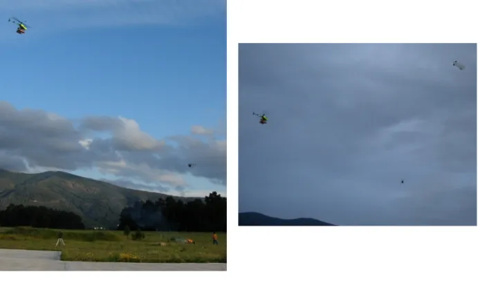
Although the COMETS system could give support to a wide range of application, the specific problem of forest fire detection and monitoring was chosen for testing and validation purposes. UAVs cooperation is very valuable in this highly challenging context. Missions involve fire alarm detection, confirmation and localization, and fire monitoring. Several field tests with controlled fires have been carried out during the past years. Figure 1 shows some pictures of these experiments.
Figure 1: Left Marvin and Heliv during a experiment. Right, Karma flying over Marvin and Heliv in a cloudy day.
The following UAVs were deployed during the COMETS experiments: the helicopter Marvin, the airship Karma and the helicopter Heliv. Marvin is an autonomous helicopter developed by the Real-Time Systems & Robotics Group of the Technische Universität Berlin (Remuß, Musial & Hommel, 2002). Karma is an autonomous 18m3 electrically propelled airship developed by LAAS (Laboratoire d'Architecture et d'Analyse des Systèmes) at Toulouse (Lacroix, Jung, Soueres, Hygounenc & Berry, 2003). Heliv is the result of the evolution of a conventional remotely piloted helicopter which has been transformed by the Robotics, Vision and Control
Group at the University of Seville by adding sensing, perception, communication and control functions. Figure 1 shows the three vehicles during the field experiments presented in this paper. The rest of the paper is structured as follows. Section 2 presents the cooperative perception system for UAVs including the hardware and software architectures and communications. Section 3 describes some of the computer vision techniques included in the perception system, with special emphasis on techniques for stabilization of sequences of images, image segmentation and image geo-location. Section 4 deals with the cooperative perception algorithms. Section 5 presents field experiments on autonomous fire detection, fire alarm confirmation and localization with cooperating UAVs. Conclusions and acknowledgements are the final sections.
2. The Perception System
This section presents the multi-UAV distributed perception system with special emphasis on sensors, its software architecture and communications.
2.1 Sensors
The UAVs are heterogeneous also in the sense of the sensors carried by them. They are equipped with DGPS, gyroscopes and Inertial Measurement Units and other sensors required for navigation. The main environment perception sensors considered in this paper are visual and infrared cameras, and a specialized fire sensor.
Marvin carries a fire sensor, whose main component is a photodiode set-up to limit its sensibility to the band of [185, 260] nm, normally associated to fires. The output of the sensor is a scalar value, proportional to the radiation energy, received every 2 seconds. Being a magnitude sensor, it is not possible to determine if a measure is due to a big fire far away or a nearby small fire. Also, the sensor cannot directly provide the position of the fire. Section 4 will present the procedure used to detect and localize fires by using this sensor. Marvin also carries a Canon S40 digital photo camera.
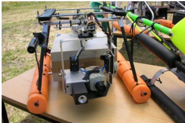
Heliv is equipped with infrared and visual video cameras. Each video camera is connected to a video server which digitizes and sends the image streams using standard net protocols. The infrared camera is a low-cost non-thermal OEM micro-camera (see Figure 2 right) in the far infrared band (7-14 microns). The visual camera is a low-weight color device with 320x240 pixel resolution.
Both helicopters, Marvin and Heliv, have motorized pan and tilt units that allow orientating the cameras independently from the body of the vehicle (see Figure 2 left). Those units have encoders that measure the pan and tilt angles.
Finally, Karma carries a stereo bench with two visual cameras in order to generate depth maps. These cameras are also used for event monitoring.
Figure 2: Left: Infrared and visual cameras of Heliv mounted in the pan and tilt unit. Right: detail of the infrared micro-camera.
2.2 Software architecture
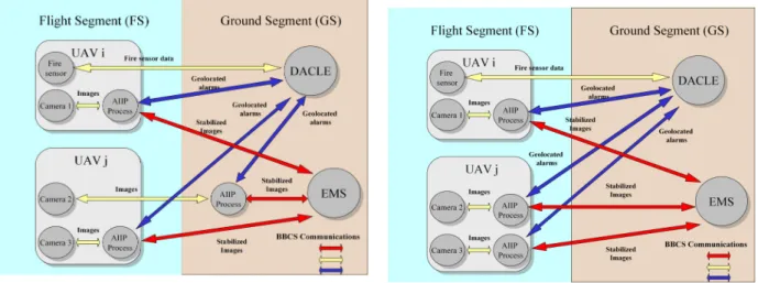
Figure 3 shows the software architecture of the Perception System (PS). This system consists of a distributed subsystem, called Application-Independent Image Processing (AIIP), and two centralized subsystems (which deal with the cooperative algorithms): Detection/Alarm
Confirmation, Localization and Evaluation Service (DACLE) and, the Event Monitoring System
Figure 3: PS subsystems interconnection and architecture. The communications system employed allows to locate the AIIP on-board UAVs (in the FS) or on ground (in the GS) transparently. Left: partially distributed configuration. Right: fully distributed configuration.
The AIIP subsystem is the processing front-end, the module of the Perception System closest to the sensors. There is one AIIP module for each camera, and for each UAV, its AIIPs can be located on-board if they have enough processing capabilities (case of UAVi of Figure 3) or on ground stations, otherwise (case of UAVj of Figure 3 left). The AIIP applies a first processing step over the data, reducing its dimensionality (and hence, the bandwidth needed to transmit them). The AIIP mainly deals with the low-level image processing functions that are common to the DACLE and EMS subsystems such as stabilization of image sequences, segmentation and geo-referencing. These functionalities will be described in Section 3. Also, the AIIP acts as a virtual image channel, being able to modify the resolution and region of interest of the images. The objective of the DACLE is to perform fire detection/alarm confirmation and localization. At its request, the DACLE subsystem receives information about possible fire alarms and other data from the AIIPs of the UAVs. DACLE applies sensor data fusion techniques to exploit the complementarities of the information gathered by the different sensors on board the different UAVs. Particularly, DACLE performs cooperative reliable detection and includes techniques for false alarm reduction. It also improves the localization of the alarms by fusing the locations given by the sensors of several vehicles and taking into account their uncertainties in a statistical framework. These techniques are presented in Section 4.
The EMS is in charge of the multi-UAV fire monitoring functionalities. This subsystem is not described in this paper due to space limitations.
2.3 Communications
The distributed perception system employs a custom communication system, called BlackBoard Communication System (BBCS) as communication layer for the different subsystems. The BBCS, developed by the Technical University of Berlin (Remuss, Musial & Brandenburg, 2004), (Remuss & Musial, 2004), is implemented via a distributed shared memory, called blackboard. The consistency of this shared memory is ensured by a real-time aware protocol. The BBCS API also offers a set of functions to deal with wireless communications and include functions robust to periods of degraded bandwidth, not infrequent in forest scenarios. Its high configuration capability allows implementing network communications with low delay using a simple software structure.
The BBCS is built on top of existing transport layers (UDP, TCP), and can be adapted to different kinds of operating systems and hardware platforms (ranging from PCs to microcontrollers), always offering the same services and interfaces. The subsystems of the PS can then be located on board the UAVs or on laptops on the ground, over different architectures, without significant changes in the configuration of the network.
3. Low level perception techniques
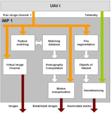
This section presents some of the functionalities currently considered within the AIIP subsystem (outlined in Figure 4). These functions are required for automatic forest fire detection and localization. Although tested for this specific scenario, it should be noted that these tools, as well as the cooperative techniques described in Section 4, can be adapted to a wide spectrum of applications.
Figure 4: Scheme of AIIP functionalities and their relations.
3.1 Fire segmentation
Fire segmentation is a function of the AIIP essential for fire detection, carried out by DACLE. The main objective is to differentiate fire pixels from background pixels. Two segmentation techniques have been applied depending on the type of image: visual or infrared. A binary correction algorithm is applied in both cases after segmentation to filter out isolated fire and background pixels (Haralick & Shapiro, 1992).
3.1.1 Fire segmentation in visual images
The technique used is a training-based algorithm similar to those described by Kjedlsen & Kender (1996) and Philips, Shah & da Vitoria-Lobo (2002). The method requires some training images in which an experienced user has determined the pixels that correspond to the fire. In the training stage a RGB histogram is built by adding Gaussian-type distributions centered at the RGB coordinates of the pixels considered as a fire pixel in the training images. If the pixel is considered as background in the training images, a Gaussian-type distribution centered at the RGB coordinates is subtracted from the RGB histogram. Finally, this RGB histogram is thresholded and a look-up table for the RGB color space is built. The look-up table contains a
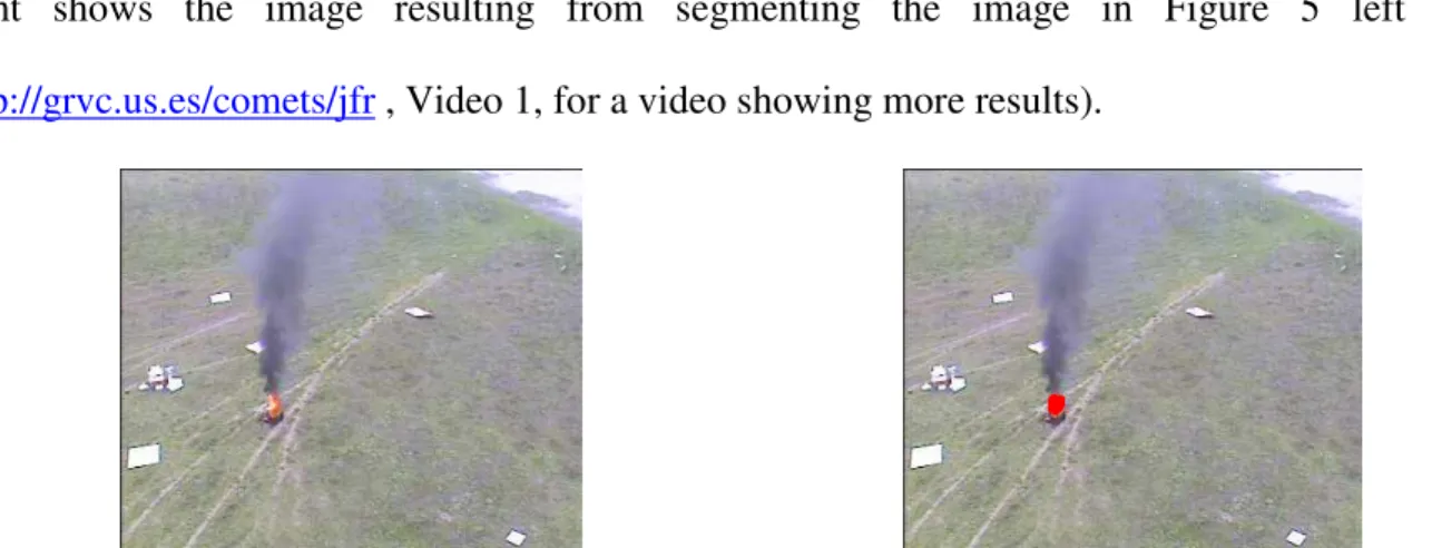
Boolean value indicating whether the color represents fire or background. In the application stage the RGB coordinates of the pixels are mapped in the trained look-up table and are considered fire pixels if the value in the look-up table is ‘1’ and, background otherwise. Figure 5 right shows the image resulting from segmenting the image in Figure 5 left (See
http://grvc.us.es/comets/jfr , Video 1, for a video showing more results).
Figure 5: Left: Visual image of a fire experiment; Rigth: the resulting segmented image.
3.1.2 Fire segmentation in infrared images
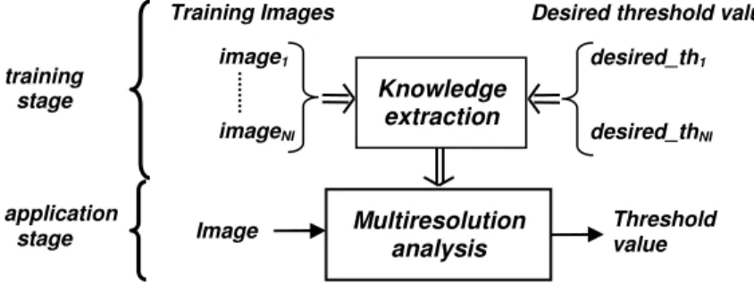
The infrared camera used in the experiments was a low-cost OEM non-thermal camera. It does not provide temperature measures but estimations of the radiation intensity throughout the scene. Black and white colors represent low and high radiation intensities, respectively. Thresholding is proposed for fire segmentation. For robust fire segmentation, the thresholding technique should consider the particularities of the application. The solution adopted was to use the training-based thresholding method described in Martínez-de Dios & Ollero (2004). Its main idea is to extract the particularities of a computer vision application and use them to supervise a multiresolution histogram analysis. The technique is applied in two stages: training and application, see Figure 6. The training stage requires a set of training images and their corresponding desired threshold values given by an experienced user. The training stage identifies the conditions under which pixels should be considered to belong to the object of interest. These particularities are introduced in a system via ANFIS training method (Jang, 1993). In the application stage, features of the image are used to determine a suitable threshold value according to these particularities. A
detailed description can be found in Martínez-de Dios & Ollero (2004). At
http://grvc.us.es/comets/jfr , Video 2 shows some results.
Figure 6: General scheme of the training-based threshold selection
.
3.1.3 Characterization of the fire segmentation algorithms
The previous algorithms are used for fire detection. The vehicles of the fleet will cooperate to reduce the number of false alarms by means of data fusion (see Section 4), and this requires the probabilistic characterization of the above segmentation algorithms. The algorithms are modeled by the probabilities PD of detection and PF of false positive outputs. These values have been
experimentally determined for both algorithms with a large set of images, some of which present actual fires. The probabilities have been computed as follows:
• PD is the ratio between the alarms correctly detected and the total number of fire alarms
presented in the set of images.
• PF is the ratio between the number of images where the algorithm detected fire
incorrectly and the total number of images of the sequence.
Table I shows the obtained values for the algorithms used for fire segmentation in visual and infrared images.
TABLE I
CHARACTERISTIZATION OF FIRE SEGMENTATION ALGORITHMS
IR Visual PD 100% 89.2% PF 8.9% 3.1% Knowledge extraction Training Images image1 imageNI desired_th1 desired_thNI
Desired threshold values
Image Multiresolution Threshold value
analysis
training stage
application stage
3.2 Geolocation
The determination of the geo-referenced location of the objects observed on the images is required for many applications. Besides, it is very useful to obtain an estimation of the uncertainty in the computed location.
The sensors onboard the different UAVs are used to compute, in a global and common coordinate frame, the position and orientation of each UAV itself and also of the sensors that are carried on board (these position and orientation will be denoted by xs). For the later, the UAV attitude angles measured by the IMU units have to be combined with those of the pan and tilt devices. Also, the UAVs provide an estimation of the covariance matrix Cs of the errors of these quantities.
If the camera is calibrated and a digital elevation map, denoted by D, is available, it is possible to obtain the geo-referenced location xm of an object in the common global coordinate frame from
its position on the image plane, o:
) , , ( s D m f o x x = (1)
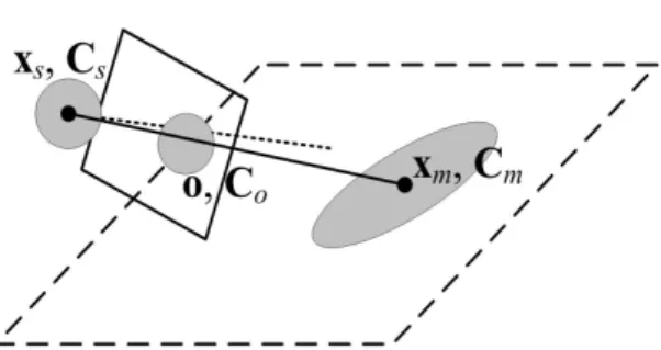
The function f inverts the camera projection obtained by, for example, a pin-hole model of the camera. This model is obtained through calibration for all the cameras, using the algorithm developed by Zhang (2000). Clearly, the function f is non-linear, and in the general case the dependence on the map D cannot be expressed analytically. Notice that the errors in the position and orientation of the camera (represented by Cs) and the errors in the position of the object on the image plane (represented by Co) are propagated into xm (see Figure 7) through (1). The
covariances Cm of these errors are estimated by using the so-called Unscented Transform (Julier & Uhlmann, 1997), (Schmitt, Hanek, Beetz, Buck & Radig, 2002).
The Unscented Transform is chosen because it allows to consider a more general class of functions than the usual first order expansion. Also the estimated covariance matrix is more
Thus, by using the geolocation procedure, each UAV will provide measures of the form [xm,Cm], where xm is the measured geo-referenced location of the event of interest (for instance, a segmented fire given by the segmentation functions) in the common coordinate frame and Cm is the estimated covariance of the errors on this location.
Figure 7: Scheme of the uncertainty propagation during the geolocation process.
3.3 Feature matching and stabilization
Many applications, such as monitoring, require having motion-free sequences of images. Thus, tools to compensate the motion induced on the image plane by the motion of the UAV are required. Using these tools, the AIIP system can provide sequences of stabilized images. The approach adopted obtains the apparent image motion by means of a robust interest point matching algorithm, and compensates the motion by warping the images to a common image frame. For specific configurations, the image motion model used for this warping is a homography.
3.3.1 Feature matching method
The computation of the approximate ground plane homography needs a number of good matching points between pairs of images in order to work robustly. The image matching method adopted is related to that described by the authors in Ferruz & Ollero (2000), with significant improvements (Ollero, Ferruz, Caballero, Hurtado & Merino, 2004). Although the same feature selection procedure of corner points is used, and a combination of least residual correlation error and similarity between clusters of features is still the disambiguation constraint, a new matching strategy has been implemented. Instead of searching for individual matching points, clusters are built as persistent structures and searched for a whole. This allows to change the disambiguation
algorithm from a relaxation procedure to a more efficient predictive approach. Selected matching hypothesis are used as starting points to locate a full cluster; the position of additional cluster members is predicted from the cluster deformation model.
The practical result of the approach is to drastically reduce the number of matching tries, which are by far the main component of processing time when a significant number of features have to be tracked, and large search zones are needed to account for high speed image plane motion. This is the case in non-stabilized aerial images, especially if only video streams of relatively low frame rate are available (see http://grvc.us.es/comets/jfr, Video 3, for some results).
As explained in Ollero et al. (2004), the detected corners define image windows which are tracked in subsequent frames; the result of such tracking is a set of window sequences. For a cluster of windows , Φi =
{
1, 2 n}
, the shape similarity constraints that must hold are equivalent to assume that the changes in window distribution can be approximately described by euclidean transformation and scaling. The effects of noise and the innacuracies of the model are accounted for through tolerance factors.Under the assumption that such constraints hold, it is easy to verify that two hypothesized matching pairs allow to predict the position of the other members of the cluster. The generation of candidate clusters for a previously known cluster can start from a primary hypothesis, namely the matching window proposed for one of its window sequences (see Figure 8), selected because of the low grey-level residual error between it and the last known window of the sequence. This assumption allows to restrict the search zone for other sequences of the cluster, which are used to generate at least one secondary hypothesis. Given both hypothesis, the full structure of the cluster can be predicted with the small uncertainty imposed by the tolerance parameters, and one or several candidate clusters can be added to a data base. The creation of any given candidate cluster can trigger the creation of others for neighbour clusters, provided that there is some overlap among them; in Figure 8, for example, the creation of a candidate for cluster 1 can be
used immediately to propagate hypothesis and find a candidate for cluster 2. Direct search of matching windows is thus kept to a minimum.
At the final stage of the method, the best cluster candidates are used to generate clusters in the last image, and determine the matching windows for each sequence. Cluster size is used as a measure of local shape similarity; a minimum size is required to define a valid cluster. If a matching pair cannot be included in at least one valid cluster, it will be rejected, regardless its residual error.
Figure 8: Generation of cluster candidates.
3.3.2 Homography computation
By using the above algorithm, a set of matches between two consecutive images can be computed. The main idea here is to compute an image motion model from these matches and, then, inverse this model to undo the motion induced in the image.
The motion model selected is a homography, so a planar surface or a pure camera rotation are assumed as hypotheses. Homography-based techniques have been proven to be frequently valid for aerial images: planar surface model holds if the UAV flies at a sufficiently high altitude; and pure rotation model holds for a hovering helicopter. Thus, if a set of points in the scene lies in a plane, and they are imaged from two viewpoints, then the corresponding points in images i and j
are related by a plane-to-plane projectivity or planar homography (Faugeras, Luong & Papadopoulo, 2001), H:
j i
sm~ =Hm~ , (2)
where m~k =
[
uk,vk,1]
is the vector of homogenous image coordinates for a point in image k, H is a 3x3 non-singular matrix and s is a scale factor.Only four correspondences are needed to determine H. In practice, more than four correspondences are available by using the above matching procedure, and the overdetermination is used to improve accuracy. A robust outlier rejection procedure is used in this work, based on LMedS (Least Median Square Estimator) and further refined by the Fair M-estimator (Xu & Zhang, 1996), (Zhang, 1996), (Zhang, 1995). Once the homography matrix H has been computed, the images are warped to a common frame. The warping was optimized due to real-time constraints (Ollero et al., 2004). The computation time for motion compensation in images of 384x287 pixels is 30 ms. in a Pentium III at 1GHz (see http://grvc.us.es/comets/jfr, Video 4, for a stabilized sequence). Figure 9 shows a mosaic of the scenario of the field experiments of Section 5 built from images gathered by the blimp Karma of the LAAS team using the stabilization procedure techniques to reduce the global image positioning error.
Figure 9: Mosaic of Lousa airfield (Portugal). Mosaic constructed using more than 500 images taken by Karma. The square shows a detail of the mosaic.
4. Cooperative fire detection
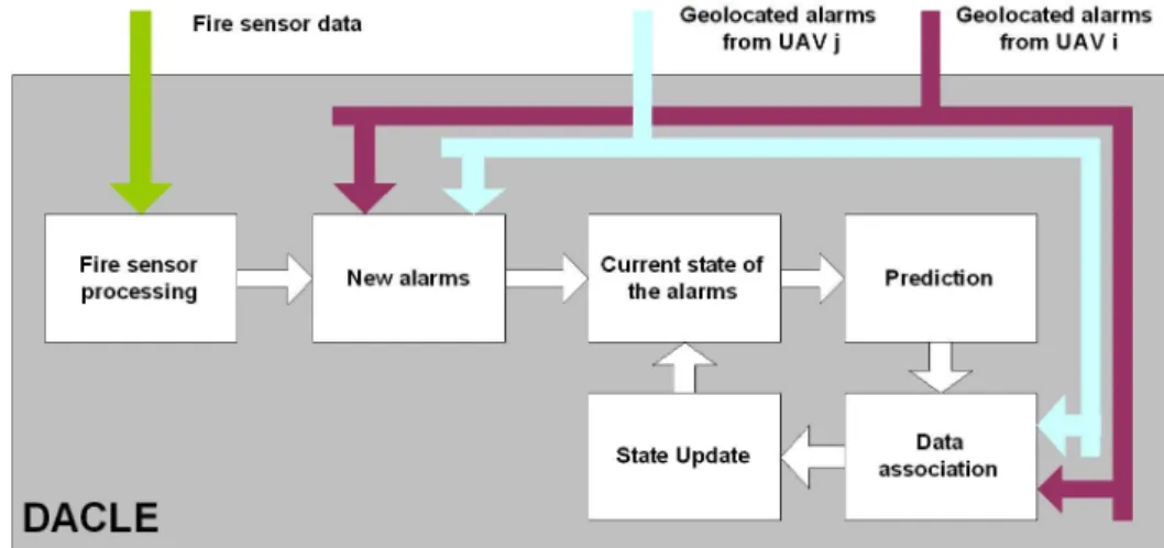
The objective of the DACLE subsystem is, from the measures provided by each vehicle of the fleet, to cooperatively estimate the geographical location of potential fire alarms while trying to reduce the number of false alarms. The DACLE subsystem can receive as measures the fire sensor data from Marvin and the geolocated fire alarms from the AIIP subsystems of the UAVs that carry cameras onboard. This section extends the work presented in Merino, Caballero, Martínez-de Dios & Ollero (2005). There, the authors presented the algorithms to deal with information provided only by cameras. Here, this work is extended to cope with fire sensor data and the final scheme is presented. Figure 10 shows a scheme of the DACLE operation.
At time k, the current information about every alarm i stored by DACLE is defined by
[
xai(k),Cai(k),pi(k)]
. where xai(k) is the estimated geo-referenced location for alarm i at time k,Cai(k) is the estimated covariance matrix of the errors in xai(k) and pi(k) is the estimated
Figure 10: Scheme of the DACLE functionalities.
The fire detection procedure consists of two stages, called detection and confirmation. 4.1 Fire detection
In this stage one or several UAVs are commanded to survey non-overlapping areas searching potential fire alarms. In this case, no cooperative perception is actually performed, but each UAV sends to the Control Centre the position of the alarms. Two different data sources come from the UAVs: images and data from the fire sensor.
4.1.1 Detection of fire alarms in images
By using the fire segmentation and geolocation algorithms of the AIIP subsystem, the UAVs equipped with cameras provide direct estimations of the locations xai(k) and the covariance
Cai(k) of the fire alarms. These estimations are complemented by the probabilities PD and PF
associated to the fire detection algorithms. These values are used to compute the initial probability pi(0) as: F D D i P P P p + = ) 0 ( (3)
The justification of this expression will be given in Section 4.2, where it will be proven that the expression considers an initial probability of fire at position xai of value 0.5.
The fire sensor provides a scalar value indicating the presence of fire. Using a threshold, this value is used to obtain a Boolean value, s, indicating that a fire alarm is present. To estimate the position of the alarm a grid-based localization technique is used. Each cell i of the grid is associated to an area of the searching zone of the UAV centered at position xi. Cell i is assigned with a value, p(xi
k), that represents the probability that fire alarm is present in its area at time k
(see Figure 11 left). The values of the grid are updated iteratively with the new data gathered by the sensor. At time k=0, with no information about the presence of fire alarms, all the cells are initiated with p(xi
0)=0.5. When a new measure sk+1 arrives, the conditional probability
p(xi
k+1|sk+1) for each cell within the field of view of the sensor is computed. p(xik+1|sk+1) is the
probability of having a fire alarm in cell i conditioned to sk+1. p(xik+1|sk+1) is computed by using
the well-known Bayes rule:
+ + + + = i k i k i k k i k i k k k i k d p s p p s p s p x x x x x x ) ( ) ( ) ( ) ( ) ( 1 1 1 1 (4)
The sensor model p(sk+1|xik) used in (4), the probability of having the measure sk+1 given a fire at
location xi , is also characterized by the probabilities P
D and PF of the sensor, as in Section 3.1
for the image-based detection algorithms. The integral in (4) is a sum over the two possible states of cell i (having fire, i.e. TRUE, or not, i.e. FALSE). If sk+1 is TRUE (that is, a fire is detected in
the field of view of the fire sensor), (4) becomes:
[
1 ( )]
) ( ) ( ) ( 1 1 k i F k i D k i D k k i p P p P p P TRUE s p x x x x − + = = + + , (5)while if sk+1=FALSE, then the update equation is:
[
1 ( )]
) 1 ( ) ( ) 1 ( ) ( ) 1 ( ) ( 1 1 k i F k i D k i D k k i p P p P p P FALSE s p x x x x − − + − − = = + + (6)The values of the cells of the grid within the field of view of the fire sensor are recursively updated using (5) and (6) as new data gathered by the fire sensor arrive. The field of view of the sensor is defined by a maximum range and the horizontal and vertical aperture angles (see Figure
11 left). The actual values of PD and PF in equations (5) and (6) depend on the relative position
of cell i respect to the sensor. Both values decrease with the distance from the cell to the sensor and with the angles that the cell forms with the sensor.
When a set of connected cells of high probability (higher than 0.7) is obtained, then an alarm is generated and the mean position of this region xai is computed. The second order moments of the
region of cells are used as an estimation of the covariance of the localization errors, Cai. Figure
11 right shows a high probability region in the grid, with these moments represented as an ellipse. As a result, the processing of the fire sensor generates also alarms of the form [xai, Cai,
pi].
Figure 11: Left: Scheme of the fire sensor field of view. The cells within a maximum distance from the sensor are updated when new sensor data are available. Also, the field of view is defined by horizontal and vertical aperture angles (here, only the horizontal angle is shown). Right: a set of cells of high probability. Its mean position and second order moments are computed, and a fire alarm is raised.
4.2 Fire alarm confirmation
When a fire alarm is detected and localized, the mission is replanned, and more UAVs are sent to confirm the alarm using their cameras. The objective is to cooperatively re-estimate the state of the alarms by fusing the fire measures gathered by all these UAVs. Figure 12 illustrates the procedure that consists of the following stages: Prediction, Data Association and Update.
Figure 12: Alarms tracking scheme. Left: prediction. The previous detected alarms and their uncertainties (presented as ellipses). Center: The UAVs gather new measures. These measures are associated to the tracks of the currently-detected alarms. Right: the update stage reduces the uncertainties of the tracks with the new data inputs. New tracks are added.
4.2.1 Prediction stage
As previously stated, A(k)=
{
[
xai(k),Cai(k),pi(k)]
,i=1, ,L(k)}
is the list of all the potentialalarms in time k, where L(k) is the number of alarms at time k. In this stage A(k) is used to predict the states of the alarms at time k+1. For such a prediction, a motion model for the alarms is required. Through this paper, the positions of the alarms are assumed to be static, i.e.
A(k+1)=A(k). This is realistic for the scenario considered, and also allows the measures to be
fused with arbitrary latency (Ridley, Nettleton, Sukkarieh & Durrant-White, 2002). However, the same scheme could be used with more complicated models, such as moving vehicles in traffic surveillance applications.
4.2.2 Data association
At time k+1, using the fire segmentation and geolocation procedures of Sections 3.1 and 3.2, the AIIP subsystems of the different UAVs provide a set of measures of the form:
[
]
{
( 1), ( 1), , , 1, , ( 1)}
) 1 (k+ = k+ k+ P P j= N k+ M xmj Cmj Dj Fj , (7)where N(k+1) is the total number of measures provided by the UAVs at time k+1, xmj(k+1) is the
estimated position of each measure, Cmj(k+1) is the estimated covariance matrix for the errors in
Data association tries to assign each measure j in M(k+1) with one alarm i in A(k), see Figure 12, center. A well-known gated nearest neighbor technique is used (Feder, Leonard & Smith, 1999). The measure j is associated with alarm i if they satisfy:
2 1
2(k 1) [ (k) (k 1)] (k 1)[ (k) (k 1)] d
dij + = xai −xmj + TS−ij + xai −xmj + ≤ , (8)
where Sij(k+1)=Cai(k)+Cmj(k+1). If xai(k) and xmj(k+1) are Gaussian, d2ij(k+1) follows a
χ
2distribution. d2 is chosen as 9 (less than 0.1% probabilities that a correct association gives a
greater value (Feder et al., 1999), (Bar-Shalom & Fortmann, 1987)).
If there are more than one measure provided by the same UAV that accomplish (8), then the nearest (that of minimum dij(k+1)) is chosen as the correct association with alarm i. Several
measures from different UAVs can be associated to the same alarm. 4.2.3 Update stage
Assume that measures {j=1,…,Mi} have been associated to alarm i. Then, the estimated position
xai and covariance matrix Cai are updated by the following equations:
) 1 ( ) 1 ( ) ( ) 1 ( 1 1 1 1 1 + = − + − + + + − + − k k k k i mM m ai ai C C C C (9)
[
( ) ( ) ( 1) ( 1) ( 1) ( 1)]
) 1 ( ) 1 ( 1 1 1 1 1 + + + + + + + + = + k − k k − k k − k k k ai ai ai m m mMi mMi ai C C x C x C x x (10)These equations follow the information form of the Kalman filter scheme as described in (Ridley et al., 2002). This leads to a reduction on the uncertainties on the location of the alarm, as illustrated in Figure 12, right.
The probability pi(k) of being a fire alarm is updated following the Bayes rule. Assuming that the
measures from different cameras are independent (each one characterized by PDj, PFj), pi(k) is
updated by the following expression:
[
1 ( )]
) ( ) ( ) ( ) ( ) ( ) 1 ( 1 1 1 k p P P k p P P k p P P k p i FM F i DM D i DM D i i i i − + = + (11)been associated to any fire measure from this UAV, the probability of alarm track i is updated by the following expression:
[
1 ( )]
) 1 ( ) ( ) 1 ( ) ( ) 1 ( ) 1 ( k p P k p P k p P k p i F i D i D i − + − − − = + (12)Finally, if a measure j has not been associated with any of the alarms, then a new alarm track is initialized (see Figure 12, right). The prior belief of this new alarm track pi(k+1) is computed as
in (3). Expression (3) follows from (11) considering a probability pi(k)=0.5.
Using equations (11) and (12), the systems discard as false alarms those tracks whose probabilities drop below a given threshold (0.2), while confirms those over a probability of 0.9. 5. Field Experiments
The perception system and all the techniques described in previous sections have been tested during field experiments carried out at the airfield of Lousa, Portugal. The experiments were performed with real controlled fires in order to test the system in close-to-operational conditions. The vehicles presented in the introduction participated in these experiments. Figure 13 shows two photos of these experiments.
Figure 13: Left: Karma and Heliv involved in a real experiment at the Lousa Airfield (Portugal). Right: a view of the airfield from Marvin.
The mission described below is a particular instance of a more general mission that could be called fire detection, confirmation and precise localization with several cooperating UAVs, and that could include different combinations of UAV and sensors. The mission described below was
carried out in May 2005. Aspects related to the coordination of the mission, task decomposition and task allocation are not described in the paper.
The mission is decomposed in the following stages: fire search, fire confirmation, fire
observation. The fire search stage starts by searching potential fires. In this stage, only Marvin
autonomous UAV is used. A search path is planned for it, and the fire sensor is used to look for potential fires. If one (or several) fire alarm is detected, then the fire confirmation stage starts. The task for Marvin UAV is replanned. It is commanded to hover at a safety distance from the fire alarm. Another UAV, in this case Heliv, is sent to confirm the alarm by using its infrared camera. If the alarm is found to be false, then the fire search stage is resumed. If the alarm is confirmed as a fire, then the fire observation stage starts. Then, the tasks for Marvin and Heliv are re-planned: both are commanded to hover on to the fire alarm and to synchronously obtain stabilized images of the fire from different points of view. Besides, the blimp Karma is sent to obtain overview images of the scenario. Below are some of the results obtained along the mission.
5.1 Fire search
The data from the fire sensor are processed to evolve a fire probability grid over the searching zone (Lousã airfield) by using the techniques described in Section 4.1.2. The grid covers 310x400 square meters and each cell corresponds to an area 1 m2. Initially all the cells are set to a probability value of 0.5. Figure 14 shows the initial stages of the evolution of the probability values of the grid every 40 s. Black color is low probability and white is high probability.
Figure 14: Evolution of fire probability of the grids cells. White indicates high probability and black low probability.
Connected cells with high probability (higher than 0.7) are considered as fire alarms and their locations are obtained. In the whole duration of this stage, three potential alarms are detected. They are shown in Figure 15 left. Figure 15 shows a georeferenced schematic map of the Lousa airfield. The solid polygonal object represents the concrete area where the UAVs take off and land. The axes are shifted UTM coordinates in meters. Only one of the three fire alarms is a true fire. The position of the controlled fire is marked with a solid square:
560 570 580 590 600 610 620 630 640 650 660 0 20 40 60 80 100 120 140 560 570 580 590 600 610 620 630 640 650 660 0 20 40 60 80 100 120 140
Figure 15: Left: Fire search stage. Fire alarms detected using the fire sensor. The ellipses represent the uncertainties in the computed positions of the alarms. The square indicates the actual position of the fire. The trajectory of Marvin is shown. Right: Fire confirmation stage. New measures from Heliv (dotted ellipse) are used to refine the location of the alarms. Heliv trajectory is also shown (dotted).
5.2 Fire confirmation
During confirmation, Heliv infrared images are processed and the procedure of Section 4.2 is followed (Figure 15 right). Figure 16 shows the previously detected alarms projected onto the segmented infrared images (also the uncertainty ellipses on their locations). The white patch is a region segmented as fire in the infrared image. Only one of the three uncertainty ellipses associated to alarms intersects its area. Thus, following (12), the probabilities pi for the two other
alarms are decreased. The associated data are used to update the probability of being fire for each object, and also to refine the estimation of its location using equations (9), (10), (11) and (12) (see Figure 16).
Figure 16: Current alarms projected on the image plane of segmented infrared images. The ellipses indicate the uncertainty on the projection. Two ellipses do not intersect the fire segmented on the image and are considered to be false alarms.
Figure 17 shows how the uncertainties in the position of the true alarm are recursively reduced, while the probabilities of the false alarms drop to values close to 0, when the alarm information obtained from the fire sensor is combined with the data from the infrared camera of Heliv. Table II presents the position of the fire alarm (mean and standard deviation) estimated with the fire sensor and the infrared camera. The actual location of the controlled fire measured using a GPS is also shown. The similarities between the actual and estimated position are evident.
460 480 500 520 540 560 580 600 620 0 5 10 15 Easting S td . d ev ia tio n (m ) 460 480 500 520 540 560 580 600 620 0 5 10 15 Northing S td . d ev ia tio n (m ) 460 480 500 520 540 560 580 600 620 0 0.5 1 1.5 Height S td . d ev ia tio n (m ) 460 480 500 520 540 560 580 600 620 0 0.1 0.2 0.3 0.4 0.5 0.6 0.7 0.8 0.9 1 P ro ba bi lit y
Figure 17: Evolution in the localization of the alarm. Left: The graphic shows the estimated standard deviation for the location of the alarm (Easting, Northing and Height). The alarm is obtained from the fire sensor data at time 450. The initial errors are high. Around time 570, images from Heliv are used to confirm the alarm and to refine the position. Right: evolution of the probabilities of the three alarms.
TABLE II
ESTIMATED FIRE POSITION AND UNCERTAINTIES, AND GROUND TRUTH
Easting Northing Height
True location of the fire 564627 4443961 200
Final estimated location (fusion) 564628.9 4443961.4 200.04
Estimated standard deviation 1.5 2 0.28
5.3 Fire observation
Once the detection phase has concluded, the observation phase starts. Marvin and Heliv are commanded to hover on to the fire (approximately forming 120º with the fire) and to send stabilized sequences of images of the event (an operator could then observe the dynamic evolution of the fire), see Figure 18. As stated in Section 1, the system allows synchronizing the vehicles to send images close in time. The images are stabilized in real-time, using the procedures of Section 3.3. Also, in some missions the blimp Karma is sent to take overview images of the zone (Figure 9 presented a mosaic built from these images). Video 5 at
http://grvc.us.es/comets/jfr summarizes the full mission.
Figure 18: During the fire observation stage, sequences of stabilized images from different points of view are obtained by using the Marvin and Heliv visual cameras.
6. Conclusions and lessons learned
Unmanned aerial vehicles (UAVs) have attracted a significant interest in many field robotics applications. The complexity of some applications requires cooperation between UAVs.
Although perception systems based on computer vision have been applied for different tasks, perception systems with multiple cooperating UAVs are scarce, especially in civil applications. The paper presents a multi-UAV cooperative perception system. The system considers heterogeneous UAVs (helicopters and blimps), with heterogeneous sensors (infrared and visual cameras, fire sensors and others). The perception system is distributed within the fleet, with functions local to the robots and a centralized part that fuses the data provided by the different UAVs. It includes local multipurpose image-processing functions such as image segmentation, stabilization of sequences of images and geo-referencing. Using these functions, the UAVs can provide estimations of the localization of objects of interest.
The main contribution of the paper is the cooperative module. This module uses a probabilistic framework to perform cooperative multi-UAV detection and tracking. The module allows to determine the belief on the status of objects of the same class (for instance, fire alarms) from estimations provided by each UAV locally. The advantage of this approach is that, if the processing can be carried out on-board, the required bandwidth to transmit the local estimations is greatly reduced.
An important aspect of the system is the proper probabilistic characterization of the detection algorithms. Here, a simple model based on the detection capabilities and the false positive outputs is used, although more complicated models could be integrated.
The proposed perception system and algorithms has been demonstrated on-line for the autonomous detection of forest fires. The results from these experiments demonstrate that the principles can be effectively applied for fire detection and precise localization. The fusion of data from heterogeneous sensors allows to reduce the false alarm ratio. It can be seen in the results from the experiments that the false alarms generated by the fire sensor are discarded by using the images. This is very interesting, because UAVs that carry sensors with high detection capabilities but relatively high false alarm ration could be used for an initial exploration, while
other UAV can be used to discard or confirm these alarms. Moreover, the planning phase can take into account the different configurations when assigning tasks to the robots.
Also, the information is fused to estimate the position of the fire alarm. The recovered position is within 1 meter of the actual position. The experiment show that it is very important to get a good estimation of the uncertainties on the estimated position for the alarms. The Unscented Transform (Julier & Uhlmann, 1997), used to approximate the non-linear nature of the projection transformation during geolocation, allows to integrate the different sources of uncertainty (position and orientation of the robot, position of the objects on the image plane, map uncertainties) to compute the associated uncertainty to measures provided by the UAVs.
It should be noted that the multi UAV-based mission demonstrated by the proposed system is very similar (at a different scale) to fire detection operations currently performed by the fire extinguishing services but with manned helicopters and airplanes. Due mainly to the high cost, such operations are normally applied only in high-risk or high-interest protected areas. The use of the presented system UAVs has evident advantages.
The described techniques can be adapted to other kind of sensors and applications. The block fire segmentation can be substituted for other detection functions that provide the positions of objects of a certain class on the image plane. For instance, the motion estimation algorithm can be used to detect events like moving objects. The measures obtained can be integrated in the same cooperative scheme. Moreover, other segmentation algorithms tuned to other applications could be easily included.
Regarding the particular problems faced during the field experiments, there are some points that are worth to mention. Thus, when the AIIP subsystem is not onboard, it receives the raw image sequences through the wireless links. The images were compressed using JPEG in order to reduce the required bandwidth but the influence of the compression on the image processing algorithms aroused serious concern. After several experiments it was possible to determine a compression factor that guaranteed the correct operation of the perception system functionalities.
The fire segmentation algorithms from visual and infrared cameras were successfully trained to work with compressed images. The tracking functionality parameters were tuned to deal with the distortions introduced by the JPEG compressor. It is important to point out that, at least in the scope of the experiments carried out in this paper, is possible to used JEPG compression to reduce the wireless bandwidth needed to send images from the UAVs to the ground segment (DS).
Furthermore, during the experiments all the communications between the UAVs and the ground segment (GS) were carried out by using 802.11 wireless systems. Although this standard is mainly designed for static nodes, these experiments demonstrated that if the UAV motion is smooth, its speed is moderate and the distance to the wireless base is shorter that one hundred meters a robust communication channel can be established in the open field. For other conditions it would be needed a more robust data link. However, if the image processing is carried on board, the required bandwidth is considerably reduced and can be sustained by a radio-modem data link.
It is also interesting to point out how small details like the sensor coordinate system can generate serious problems from the beginning to the end of the development. If a fleet of heterogeneous UAVs have to cooperate, it is necessary to carefully set a common coordinate system for the measures given by the sensors. Incoherent coordinates systems lead to erroneous and potentially dangerous results.
Regarding future developments, in the present formulation, the cooperative algorithms for precise localization are based on the Kalman filter. The problem of data association is solved by using a nearest neighbor technique which may lead to false matches in a cluttered environment. More complex techniques as multiple hypothesis tracking (Schmitt et al., 2002) will be applied. Furthermore, pure Bayesian approaches for data fusion, based on likelihood functions, will be also researched.
Besides, the application of the proposed multi-UAV perception system to inspection of buildings (in particular thermal leakages) is object of current research, as well as the integration of multiple UAVs with wireless sensor networks.
ACKNOWLEDGEMENTS
The work described in this paper has been developed in the project “COMETS: Real-time coordination and control of multiple heterogeneous unmanned aerial vehicles” (IST-2001-34304) funded by the European Commission, 5th Framework Programme and “CROMAT: Coordinación de robots móviles aéreos y terrestres“(DPI2002-04401-C03-03) funded by the Spanish Dirección
General de Investigación. The authors especially thank the COMETS teams of the Laboratoire
d'Architecture et d'Analyse des Systèmes (LAAS) at Toulouse (that has developed the main part of the distributed decisional architecture) and the Technische Universität Berlin for their images and data and their participation in the general COMETS experiments. The authors also thank Prof. Viegas and ADAI team from the University of Coimbra (Portugal) for the support in the fire experiments, and all the other members of the COMETS team.
REFERENCES
Amidi, O., Kanade, T. and Fujita, K. (1999). A visual odometer for autonomous helicopter flight. Robotics and Autonomous Systems, 28, 185-193.
Bar-Shalom, Y. and Fortmann, T.E. Tracking and Data Association. (1987). Academic Press Mathematics In Science And Engineering Series, 179.
Bueno, S., Azinheira, J., Ramos, J., Paiva, E., Rives, P., Elfes, A., Carvalho, J. and Silveira, G. (2002). Project AURORA: Towards an Autonomous Robotic Airship. IEEE/RSJ International Conference on Intelligent Robots and Systems. Proceeding Of the Workshop WS6 Aerial Robotics (pp 43-54), Lausanne, Switzerland.
Corke, P., Sikka, P. and Roberts, J.M. (2001). Height Estimation for an Autonomous Helicopter, Lecture Notes in Control and Information Sciences, 271, 101-110.
Del-Cerro, J., Barrientos, A., Campoy, P. and García, P. (2002). An autonomous helicopter guided by computer vision for inspection of overhead power cable, IEEE/RSJ International Conference on Intelligent Robots and Systems. Proceeding Of the Workshop WS6 Aerial Robotics (pp 69-78), Lausanne, Switzerland.
Farnebäck, G. and Nordberg, K. (2002). Motion detection in the WITAS project. Proceedings of the SSAB 02 Symposium on Image Analysis (pp. 99-102), Lund, Sweden.
Faugeras, O., Luong, Q. and Papadopoulo, T. (2001). The Geometry of Multiple Images, MIT Press.
Feder, H.J.S, Leonard, J.J. and Smith, C.M. (1999) Adaptive mobile robot navigation and mapping, International Journal of Robotics Research, 18(7), 650-668.
Ferruz, J. and Ollero, A. (2000). Real-Time feature matching in image sequences for non-structured environments. Applications to vehicle guidance, Journal of Intelligent and Robotic
Gancet, J., Hattenberger, G., Alami, R. and Lacroix, S. (2005). Task Planning and Control for a multi-UAV system: architecture and algorithms, Proc. of the IEEE International Conference on Intelligent Robots and Systems, Edmonton, Canada,
Gancet, J., Hattenberger, G., Alami, R. and Lacroix, S. (2005), Distributed decision in multi-UAV systems: architecture and algorithms. Workshop on Cooperative Robotics, IEEE International Conference on Robotics and Automation, Barcelona, Spain.
Giulietti, F., Pollini, L. and Innocenti, M. (2000), Autonomous Formation Flight, IEEE Control Systems Magazine, 20, 34-44.
Hall, J.K. and Pachter, M. (1999) Formation Maneuvers in Three Dimensions, Report of the Air Force Institute of Technology.
Haralick, R.M. and Shapiro, L.G. (1992) Computer and Robot Vision (2 volumes). Reading, MA : Addison-Wesley.
Jang, J.S-R. (1993). ANFIS: Adaptive-Network-based Fuzzy Inference Systems. IEEE Transactions on Systems, Man and Cybernetics, 23(3), 665-685.
Julier, S. and Uhlmann, J. (1997). A new extension of the kalman filter to nonlinear systems, Proc. of the 11th Int. Symp. on Aerospace/Defence Sensing, Simulation and Controls, 3068 (pp. 182-193).
Kim, J.H. and Sukkarieh, S. (2003). Airborne Simultaneous Localization and Map Building, IEEE International Conference on Robotics and Automation (pp.406-411), Taipei, Taiwan. Kjedlsen, R. and Kender, J. (1996). Finding skin in colour images. Proceedings of the International Workshop on Face and Gesture Recognition (pp. 144-150).
Lacroix, S., Jung, I-K and Mallet, A. (2001). Digital Elevation Map Building from Low Altitude Stereo Imagery, Proc of the 9th International Symposium on Intelligent Robotic Systems – SIRS’01 (pp 207-216), Toulouse, France.
Lacroix, S., Jung, I-K., Soueres, P., Hygounenc, E. and Berry, J-P. (2003). In Experimental Robotics VIII: The autonomous blimp project of LAAS/CNRS - Current status and research challenges (pp. 487-496), Springer Tracts in Advanced Robotics, 5.
Martinez-de Dios, J.R. and Ollero, A. (2004). A Multiresolution Threshold Selection Method Based on Training, Lecture Notes in Computer Science, 3211, 90-97.
Merino, L., Caballero, F., Martinez-de Dios, J.R. and Ollero, A. (2005). Cooperative fire detecion using unmanned aerial vehicles. Proceedings of the IEEE International Conference on Robotics and Automation (ICRA’05) (pp. 1896-1901).
Miller, J.R. and Amidi O. (1998). 3-D Site Mapping with the CMU Autonomous Helicopter, Proceedings of the 5th International Conference on Intelligent Autonomous Systems (IAS-5). Ollero, A., Ferruz, J., Caballero, F., Hurtado, S. and Merino, L. (2004). Motion compensation and object detection for autonomous helicopter visual navigation in the COMETS system, Proceedings of the IEEE International Conference on Robotics and Automation (ICRA’04) (pp. 19- 24).
Ollero, A., Lacroix, S., Merino, L., Gancet, J., Wiklund, J., Remuss, V., Perez, I.V., Gutierrez, L.G., Viegas, D.X., Benitez, M.A.G., Mallet, A., Alami, R., Chatila, R., Hommel, G., Lechuga, F.J.C., Arrue, B.C., Ferruz, J., Martinez-De Dios, J.R. and Caballero, F. (2005). Multiple eyes in the skies: architecture and perception issues in the COMETS unmanned air vehicles project. IEEE Robotics & Automation Magazine, 12 (2), 46- 57.
Ollero, A and Merino, L. (2004). Control and perception techniques for aerial robotics, Annual Reviews in Control, 28(2), 167-178.
Philips, W., Shah, M. and da Vitoria-Lobo, N. (2002). Flame recognition in video, Pattern Recognition Letters, 23, 319-327.
Remuß, V. and Musial, M. (2004). BBCS - Efficient Communication System for Connection of Low and High-Performance Systems. Paper presented at the First European Micro Air Vehicle Conference (EMAV 2004), Braunschweig (Germany).
Remuß, V., Musial, M. and Brandenburg, U.W. (2004). BBCS - Robust Communication System for Distributed Systems. Paper presented at the IEEE International Workshop on Safety, Security and Rescue Robotics (SSRR 2004), Bonn (Germany).
Remuß, V., Musial, M. and Hommel, G. (2002). MARVIN – An autonomous flying robot based on mass market. IEEE/RSJ International Conference on Intelligent Robots and Systems. Proceeding Of the Workshop WS6 Aerial Robotics (pp 23-28), Lausanne, Switzerland.
Ridley, M., Nettleton, E., Sukkarieh, S. and Durrant-Whyte, H. (2002). Tracking in decentralised air-ground sensor networks, Proc. of the 5th Int. Conf. in Information Fusion, ICIF 2002, 1 (pp. 616-623).
Saripalli, S, Montgomery, J.F. and Sukhatme, G.S. (2003). Visually guided landing of an unmanned aerial vehicle, IEEE Transactions on Robotics and Automation, 19, 371- 380.
Schmitt, T. Hanek, R., Beetz, M., Buck, S. and Radig, B. (2002). Cooperative probabilistic state estimation for vision-based autonomous mobile robots, IEEE Transactions on Robotics and Automation, 18, 670-684.
Vidal, R., Sastry, S., Kim, J., Shakernia, O. and Shim, D. (2002). The Berkeley Aerial Robot Project (BEAR). IEEE/RSJ International Conference on Intelligent Robots and Systems. Proceeding Of the Workshop WS6 Aerial Robotics (pp. 1-10), Lausanne, Switzerland.
Xu, G. and Zhang, Z. (1996). Epipolar geometry in stereo, motion and object recognition, Kluwer Academic Publishers.
Zhang, Z. (1995). Parameters estimation techniques. A tutorial with application to conic fitting. (Inria Technical Report RR-2676), Inria.
Zhang, Z. (1996). A new multistage approach to motion and structure estimation: from essential parameters to Euclidean motion via fundamental matrix, (Inria Technical Report RR-2910), Inria.
Z. Zhang. (2000) A flexible new technique for camera calibration. IEEE Transactions on Pattern Analysis and Machine Intelligence, 22(11),1330-1334.
Zhang, Z. and Hintz, K.J. (1995). Evolving neural networks for video attitude and hight sensor, Proc. of the Int. Symp. on Aerospace/Defense Sensing and Control, 2484 (pp. 383-393), Orlando, FL.