TCP/IP over the Bluetooth Wireless Ad-hoc Network
Niklas Johansson, Maria Kihl and Ulf KörnerDepartment of Communication Systems, Lund University, Sweden (niklasj, maria, ulfk)@telecom.lth.se
Abstract. Bluetooth is a wireless ad-hoc network concept that was presented in February 1998 by its five original promoters Ericsson, Nokia, IBM, Toshiba and Intel. With Bluetooth, mobile terminals within range of each other can set up ad-hoc connections for both synchronous traffic, e.g. voice, and asynchronous traf-fic, e.g. IP-based data traffic. In this paper we analyse how well Bluetooth can carry TCP/IP traffic and in particular we show that though the radio channel is very disturbed the TCP Vegas protocol with its flow control mechanism can be carried very well. With ARQ handled at the Bluetooth level, retransmissions are made immediately after a packet error and thus the delays, normally introduced are kept acceptably short. In our model important mechanisms in TCP Vegas as well as Bluetooth mechanisms are modelled in detail and we show that TCP throughput is quite high and delays are kept short for packet error probabilities up to 50% and moderate loads.
1. Introduction
Bluetooth is a wireless ad-hoc network concept that was presented in February 1998. With Bluetooth, mobile terminals within range of each other can set up ad-hoc connec-tions. It is designed for both synchronous traffic, e.g. voice, and asynchronous traffic, e.g. IP-based data traffic. The Bluetooth Special Interest Group (SIG), led by a nine-company Promoter group including 3Com, Ericsson, IBM, Intel, Lucent Technologies, Microsoft, Motorola, Nokia and Toshiba, is driving development of the technology and bringing it to market. For more information, see [4].
Wireless ad-hoc networks have been examined in some papers. The research has mostly been focused on routing (see, for example, Johnson [21]). Perkins [22] exam-ined how mobile-IP could be used in ad-hoc networks. Davies et al. [23] suggested that token passing should be used in the MAC protocols for wireless LANs. However, only a few papers have examined Bluetooth. Haartsen [5] gives a good introduction to the technology used in Bluetooth (see also the Bluetooth Specification ver. 1.0 [6]). Johansson et al. [1][2][3] presents and examines a number of different network usage cases for Bluetooth.
In order to achieve good network performance, ad-hoc networks must ensure relia-ble data transfer for the applications. Therefore, the data packets in Bluetooth are pro-tected by an ARQ scheme on the link layer. However, it is also necessary to have good end-to-end congestion control. The obvious solution is to use the Transmission Control Protocol (TCP), that guarantees reliable, in-sequence delivery of packets (see, for example, Stevens [10]).
The congestion control in TCP uses a dynamic sliding window to control the rate at which packets are transmitted. The congestion control scheme in TCP was first devel-oped by Jacobson [9]. The most used version right now is called TCP Reno (see, for
example, Allman et al. [8]). Brakmo and Peterson [7] suggested a new congestion con-trol for TCP, called TCP Vegas. Further, they showed that with TCP Vegas, the per-formance becomes better than with TCP Reno. This was also shown by Ait-Hellal and Altman [20] and Mo et al. [19]. Therefore, we will use TCP Vegas as the congestion control scheme in this paper.
One problem that is obvious when TCP is used in wireless networks is that TCP was originally designed for networks with low packet error rate. Wireless networks usually show high rate of packet losses and these losses may trigger the congestion control in TCP even though there is no congestion. Numerous papers have examined the per-formance of TCP over wireless links. Augé and Aspas [14], Lakshman and Madhow [18] and Gerla et al. [16] found that TCP does not work well in wireless environments. However, these papers assumed that there were no link layer retransmission schemes. Chaskar et al. [15] showed that a suitable link level error recovery mechanism may improve the TCP performance in wireless networks. Ludwig and Rathonyi [13] devel-oped a link layer enhancement for GSM. Chandran et al. [17] suggested a feedback scheme for ad-hoc networks. Both Wong and Leung [11] and Chockalingam et al. [12] examined ARQ schemes for the link layer in wireless networks.
However, until now there has been no published papers on the performance of TCP over Bluetooth. In this paper, we present a detailed simulation model of TCP/IP over Bluetooth. We use this model to examine the maximum throughput and packet delays for TCP/IP traffic under various conditions. We find that Bluetooth is well suited to carry TCP/IP traffic and that both high throughput and low delays can be achieved also when the radio channel has a high packet error probability.
2. Bluetooth
Bluetooth is a short-range radio link which originally was developed to eliminate the cables between portable and/or fixed electronic devices. Today, Bluetooth is a true ad-hoc wireless network intended for both synchronous traffic and asynchronous traffic. Bluetooth consists of a number of protocols, all residing in the two lowest layers in the OSI-model, i.e. the physical and the data link layer. For a more detailed description of the system, the reader is referred to [6].
2.1 Baseband Protocol
In Bluetooth all units are peer units with identical hard and software interfaces. Two or more units sharing the same channel form a piconet, where one unit acts as a master (any unit may become a master), controlling traffic on the piconet, and the other units act as slaves.
The Bluetooth radio uses a fast frequency hopping scheme and short data packets to combat interference and fading. Furthermore, Bluetooth uses a slotted Time-Division Duplex (TDD) scheme for full duplex transmission, where each slot is 0.625 ms long. The Bluetooth baseband protocol is a combination of circuit- and packet switching, hence, time slots may be reserved for both synchronous information (Synchronous Connection Oriented, SCO link) or dynamically allocated for asynchronous
informa-tion (Asynchronous Connecinforma-tionLess, ACL link). An SCO link will always be symmet-rical, i.e. a down-link slot is followed by one uplink slot. An ACL link, however, may convey packets that covers several, continuous slots, either symmetric or asymmetric. In fact, there are two different ACL link packets, one denoted DMx for which the pay-load is FEC encoded and one denoted DHx for which the paypay-load is unprotected (the packet header is always FEC encoded). The subscript x stand for the number of slots that is required to transmit the packet.
For ACL traffic, an unnumbered ARQ scheme is applied in which data transmitted in one slot is directly acknowledged by the recipient in the next slot. If the packet is not acknowledged a retransmission takes place immediately, and thus, delay due to errors is just one slot in duration.
The system offers a gross bitrate of 1 Mbps per piconet. Based on the TDD structure, Bluetooth supports an asymmetric ACL link of maximum 721 kbps in one direction while permitting 57.6 kbps in the other direction, or a symmetric ACL link of maxi-mum 432.6 kbps. Several piconets may be linked together, thus forming a scatternet in which each piconet is identified by a unique hopping sequence, and as long as not too many, each provides a capacity of almost 1Mbps. Thus a scatternet consisting of say ten piconets, geographically on top of each other, may provide 10 Mbps.
2.2 Link Manager Protocol (LMP) and Logical Link Control and
Adaptation Protocol (L2CAP)
LMP and L2CAP are layered above the Baseband Protocol and they reside in the data link layer. The LMP is used for link set-up and control and is not further considered in this paper. The L2CAP provides connection-oriented and connectionless data services to upper layer protocols with protocol multiplexing capability, packet segmentation and reassemble, and the conveying of quality of service information.
3. TCP Vegas
In this section we shortly describe the TCP congestion control scheme used in the investigations, the so called TCP Vegas. We describe the main parts of TCP Vegas. For more information about the scheme, please refer to Brakmo and Peterson [7].
We assume that a TCP connection has been set up between two nodes. Data seg-ments are generated by an application. All segseg-ments are of the same size, called Data
Segment Size (DSS). TCP transmits the segments unchanged, i.e. no segmentation is
performed on the TCP layer.
3.1 Round Trip Time Measurements
It is important that the control scheme has good estimates of the round trip time, RTT, for a segment, that is, the time from a segment is submitted until an acknowledgement,
ACK, for the segment is received. When an ACK is received for a segment, that has not
been retransmitted, the RTT for this segment is measured. A smoothed round trip time,
This smoothed round trip time is used in the calculations of the retransmission time-out value, RTO, that determines when a segment should be retransmitted. The RTO is
calculated as where D is the smoothed mean deviation of SRTT,
given by .
3.2 Estimation of Expected and Actual Rates
The Expected and Actual rates of a connection are used in the window adjustment algorithms below. The expected rate is the estimated transmission rate for a non-con-gested connection, whereas the actual rate is the estimated current transmission rate. These rates are estimated once every RTT, by using the RTT for a marked segment. During the RTT for this marked segment, the number of transmitted segments,
Trans-Seg, are measured. The Expected rate is given by where
BaseRTT is the minimum RTT for all transmitted segments. cwnd is the current
con-gestion window, which is used as an estimate of the number of segments in transit. The
Actual rate is given by .
3.3 Window Adjustments
The congestion control is basically a sliding window flow control. The control scheme is self-clocking, that uses ACKs from the receiver to submit new segments into the net-work. The sender adjusts the congestion window, cwnd, differently depending on the phase. When there are no ACKs to receive, as in the beginning of a transmission, the scheme is in the slowstart phase. When the transmission is running smoothly, the scheme changes to the congestion avoidance phase. After a segment loss, the scheme either enters a fast retransmit and fast recovery phase or returns to the slowstart phase. Each time the window has been updated, the scheme checks if it is possible to trans-mit one or more segments. This is determined from the value of cwnd and the value of the advertised window in the receiver, rwnd. If the number of segments in transit is less than the minimum of cwnd and rwnd, new segments may be submitted.
Slowstart. The objective of the slowstart phase is to gradually increase the
number of data in transit. Since there are no ACKs coming from the receiver, the scheme must be clocked in another way. First, the cwnd is set to one segment. The window is then increased by doubling the value of cwnd every other SRTT.
The scheme switches to the congestion avoidance phase when .
Congestion Avoidance. The objective of the congestion avoidance phase is to
find a window size that allows a maximum throughput without causing congestion. Each time an ACK is received, the following is performed.
If then cwnd is increased by 1/cwnd, else
if then cwnd is decreased by 1/cwnd. Otherwise,
cwnd is unchanged.
The scheme is in the congestion avoidance phase until a segment loss occurs. A loss is detected either by a retransmission timeout or by the arrival of a so called duplicated ACK. The receiver sends a duplicated ACK each time it receives a segment that is out
572 = 6577+4' ' = '+0,25⋅(577 6577– –') ([SHFWHG = FZQG %DVH577⁄ $FWXDO = 7UDQV6HJ 577⁄ ([SHFWHG $FWXDO– ( )<1⁄%DVH577 ([SHFWHG $FWXDO– ( )<1⁄%DVH577 ([SHFWHG $FWXDO– ( )>3⁄%DVH577
of order. When a loss is detected, the sender retransmits the lost segment and then changes to one of the other phases. If there is a retransmission timeout, the scheme switches to the slowstart phase. If the sender receives three duplicated ACKs for the same segment, it switches to the fast retransmit and fast recovery phase.
Fast Retransmit and Fast Recovery. This phase uses a parameter sstresh that
is set to cwnd/2. The lost segment is retransmitted and then cwnd is set to sstresh+3. If the sender receives any more duplicated ACK for the retransmitted packet, cwnd is incremented by one for each ACK. When the first ACK arrives that acknowledges new data, cwnd is set to sstresh. After this the scheme switches to the congestion avoidance phase.
4. Simulation Model
We have developed a detailed simulation model containing both Bluetooth and TCP/ IP. The network that is modelled is a piconet in Bluetooth with two nodes. The two nodes can for example be a laptop and a server.
4.1 Transmission Procedures
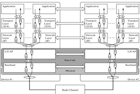
The layers in the protocol stack are shown in Figure 1. The sender’s application layer generates data segments according to some arrival process. The segments are directly transmitted to the TCP layer. The segments are put in the TCP sender buffer, where
they are delayed at least DTCP seconds. This delay models the processing needed to
add a TCP header. When the window allows it, TCP sends the segments to the IP layer. At the IP layer, the segments are put in the IP sender buffer. At regular intervals of
length DIP seconds, the IP removes a segment from the buffer and sends it to L2CAP.
The segments are put in the L2CAP sender buffer. L2CAP removes segments at
regu-lar intervals of length DL2CAP seconds, divides the segment into Bluetooth packets and
sends them to the Bluetooth Baseband sender buffer where they are delayed at least
DBase seconds. The Baseband transmits the packets according to the Bluetooth
trans-mission scheme described earlier. Transmitted Baseband packets may be lost due to bit errors. The errors are modelled with a constant loss probability, in the following called Packet Error Probability (PEP).
When the receiver’s Baseband layer receives a correct packet it is delayed DBase
sec-onds and sent to the L2CAP receiver buffer where it is delayed another DL2CAP
sec-onds. L2CAP reassembles the Bluetooth packets into TCP/IP segments and sends
them to the IP receiver buffer. At regular intervals of length DIP seconds, the IP layer
removes a segment from the buffer and sends it to the TCP layer, where it is put in the TCP receiver buffer. When TCP sends an ACK for a segment, the segment is removed from the buffer and is sent to the application layer.
The ACKs are piggy-backed on TCP segments going in the opposite direction. According to TCP, the ACKs are only sent separately if these are delayed too much or if two or more TCP segments are waiting to be acknowledged.
We find it advisable to use long, uncoded packet types for data transmission since they have the largest ideal throughput. In [1], [2] and [3] the importance of multislot
packets to increase throughput and keeping the delays low have been addressed. Uncoded packet types, i.e. DHx packets, have on average a 55% larger payload size than coded packet types, i.e. DMx packets. This means that 1.55 DMx packets are needed to be able to pass the same amount of information as can be passed in a single DHx packet. For a Packet Error Probability (PEP) of around 36% for DHx packets we obtain the same goodput as when using DMx packets not effected by errors. Further, the DMx packets can also become corrupted which means that even more DMx pack-ets have to be sent. Therefore, we have decided to only use DHx packpack-ets in the simula-tions.
4.2 Data Packet Formats
A packet that arrives at the Bluetooth layer consists of three parts: A TCP header, an IP header and payload. L2CAP adds 4 bytes as channel identification and packet length. We have decided to use a total packet size that is as close to 1500 bytes (i.e the Ether-net packet size) as possible with the constraint that it should fit into a number of Blue-tooth packets.
The TCP header is 32 bytes instead of the normal 20 bytes. The extra 12 bytes are necessary for the RTT calculations. The IP header is 20 bytes. With a payload of 1429 bytes, that is a total packet size of 1485 bytes, the packet fits into 55 Bluetooth packets of type DH1.
Normally, the ACKs are piggy-backed on TCP segments going in the opposite direc-tion. When a separate ACK is sent this packet only consists of the headers, which means that it is 56 bytes long. A separate ACK is divided into 3 DH1 packets.
Radio Channel L2CAP Network Layer Network Layer Device #1 Physical Application Application Transport Transport Layer Layer L2CAP Device #2 Network Layer Network Layer Transport Transport Layer Layer Application Application Baseband Baseband Data Link (TCP) (TCP) (TCP) (TCP)
(IP) (IP) (IP) (IP)
4.3 Model Parameters
The model parameters are shown in Table 1. The data segment size (DSS) is the one described above. The maximum receiver window is set as in [7]. The lower and upper
bounds in the window adjustment algorithm (α and β) are set as in [7]. The other
parameters are set to what we believe are realistic values for this system.
5. Investigations
The objective of the investigations is to examine the combination of TCP/IP and Blue-tooth.
5.1 Arrival Process
The arrival process determines how the application layer delivers data to the TCP layer. We use two different arrival processes. In the first case, we want to find the max-imum throughput for the system, which means that the TCP layer must always have data to send. Therefore, the arrival rate of application data is always high enough in order for the queues on the TCP layer to be filled.
In the second case, we assume a more bursty application process. This process is modelled by an Interrupted Bernoulli Process (IBP), i.e. for a geometrically distributed period (active state) arrivals occur according to a Bernoulli process. This period is fol-lowed by another period (idle state) during which no arrivals occur, also this geometri-cally distributed. Given that we are in the active state, the process will stay in this state with probability 1-p or it will go to the idle state with probability p. If the process is in the idle state it will stay there with probability 1-q or go to the active state with
proba-bility q. When in active state, a slot contains a packet with probaproba-bility λ=1. The time
slots for the traffic generators are aligned with the time slots for the modelled piconet.
The squared coefficient of variation, C2, for the packet arrival times are used as a
measure of burstiness in the simulations. Table 1. Model parameters
Parameter Value
Data segment size (DSS) 1429 bytes
Maximum receiver window (Max rwnd) 12 segments, i.e 17.148 kbytes Total buffer size on Bluetooth layer 15 kbytes
Segment delay on TCP layer (DTCP) 1 µs
Segment delay on IP layer (DIP) 1 µs
Segment delay on L2CAP layer (DL2CAP) 1 ms Segment delay on Baseband layer (DBase) 1 ms Lower bound in TCP Vegas window adjustment (α) 1 Upper bound in TCP Vegas window adjustment (β) 3
5.2 Simulations
Two types of simulations were performed. First, we examined the maximum through-put for a number of packet error probabilities (PEPs) under varying conditions. Sec-ond, we examined the delays, i.e. the time from a data segment is generated until it has been correctly received and the receiver has sent an ACK, for predetermined packet error probabilities.
As mentioned earlier Bluetooth supports an asymmetric link of maximum 721 kbps in one direction while permitting 57.6 kbps in the return direction, or a 432.6 kbps symmetric duplex link. In order to find the maximum throughput (goodput) over a dis-turbed Bluetooth channel, we generate data segments so that there is a segment to be sent whenever the window mechanism in TCP so allows.
The goodput figures obtained are used in the delay investigations as the ‘‘TCP chan-nel capacity’’ which of course varies with different values of PEP. That means that when we in the delay investigations refer to a load on the channel this load is normal-ized to the TCP channel capacity at a certain PEP. If we generate data segments with a certain rate the load value will be different for different values of PEP.
In the delay investigations we generate data segments according to the IBP described
above. We have chosen two different values of the squared coefficient of variation, C2,
set to 1 and 50 respectively.
6. Results and Discussion
The two curves in Figure 2 show the goodput as a function of the packet error proba-bility (PEP). The upper curve corresponds to an asymmetric case and the lower to a symmetric. We find the maximum goodput for PEP=0 to be slightly less than 721 kbps and 432.6 kbps respectively. The difference is due to headers and the TCP flow control mechanism. We see that the throughput decreases dramatically when the packet error probability grows. It is notable that the Bluetooth access scheme, based on polling, used for asynchronous traffic, can handle traffic also under very high loads. This is not the case for many other ad-hoc networks relying on contention based MAC principles.
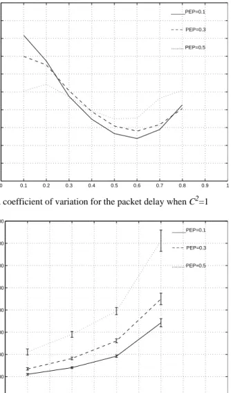
In Figure 3 the delay when C2=1 is presented as a function of the normalized load.
The three curves correspond to PEP equal to 0.1, 0.3 and 0.5 respectively. As we can see for low loads the delays decrease with load. This is due to that when the load is low the acknowledgment can just seldom be piggy-backed, and TCP then waits until there is a new ``tick’’, which comes regularly every 500 ms, before it sends an acknowledg-ment. When the load increases, more and more acknowledgments are piggy-backed on TCP packets in the return direction. However, when the load is further increased the delay increases as packets are frequently queued up in different buffers along the path. The squared coefficient of variation for the delays are shown in Figure 4. As load here is normalized it does not make sense to compare the three curves but more to see
that C2 is quite low. We will be back to the shape of the curves when we discuss.
Figure 6 also presents C2 as function of load but where we use another mechanism for
Figure 5 shows the delays when data segments are generated with a squared coeffi-cient of variation equal to 50. We see that the delays are dramatically higher compared
to the case when the data segments where generated more smoothly, i.e. when C2=1.
However even in this case the squared coefficient of variation for the delays are of the order of one.
We have also elaborated with different sizes of various buffers. In each node the total buffer size for the Bluetooth layer, i.e. below the IP-layer, was set to 15 kbytes. We found no significant changes in neither throughput nor delay when these buffers were set to half the original sizes. Furthermore we have varied the lower and upper bounds
in the TCP Vegas window adjustments, i.e. the values of α and β. Also here, our
per-0 0.1 0.2 0.3 0.4 0.5 0.6 0 100 200 300 400 500 600 700
Packet error probability
Goodput (kbit/s)
_____symmetric link − − − asymmetric link
Figure 2. Maximum throughput
0 0.1 0.2 0.3 0.4 0.5 0.6 0.7 0.8 0.9 1 0 20 40 60 80 100 120 140 160 180 200 220 Delay (ms) _____PEP=0.1 − − − PEP=0.3 ... PEP=0.5
formance measures were not significantly affected by varying these parameters within reasonable values. Performance measures will most probably be more sensitive to the values of these two parameters, when more slaves are active in the piconet.
However, when we used a fix delay (200 ms) from the time a TCP packet is received until a non-piggy-backed acknowledgment is sent, the variances for the delays were significantly decreased, while the averages were hardly affected. Figure 6 shows the squared coefficient of variance as function of load for different packet error probabili-ties. The tendency we saw in Figure 4 is here further noticable. The normalized varia-tions tend to grow for increasing low loads. For very low loads almost all TCP acknowledgments are handled by means of non-piggy-backed acknowledgements. As
0 0.1 0.2 0.3 0.4 0.5 0.6 0.7 0.8 0.9 1 0 0.1 0.2 0.3 0.4 0.5 0.6 0.7 0.8 0.9 1
Squared Coefficient of Variation
_____PEP=0.1 − − − PEP=0.3 ... PEP=0.5
Figure 4. Squared coefficient of variation for the packet delay when C2=1
0 0.1 0.2 0.3 0.4 0.5 0.6 0.7 0.8 0.9 1 0 500 1000 1500 2000 2500 3000 3500 4000 Delay (ms) _____PEP=0.1 − − − PEP=0.3 ... PEP=0.5
load increases up to 0.2 or 0.3 more acknowledgements are brought piggy-backed and the mix of the two acknowledgement types leads to an increase in the delay variations. A further increase in load leads to that piggybacked acknowledgements do dominate and thus the variations in the delays due to the effects of a mix of different types of acknowledgements decreases. For high loads the delay variations naturally growths.
7. Conclusions
Carrying TCP over wireless networks often leads to severe degradation in throughput and increased delays as the flow control mechanism in TCP reacts on delays intro-duced by retransmitting erroneous packets as if the network was congested. In this paper we have clearly demonstrated that the Bluetooth wireless ad-hoc network can handle TCP/IP traffic very well also under high packet error probabilities. Throughput is kept high and end to end delays are within reasonable limits also for quite high loads.
References
[1] P. Johansson, N. Johansson, U. Körner, J. Elg and G. Svennarp, “Short Range Radio Based
Ad-hoc Networking: Performance and Properties”, Proceedings of International
Confer-ence on Communications, Vancouver, Canada, June 1999.
[2] N. Johansson, U. Körner and P. Johansson, “Wireless Ad-hoc Networking with Bluetooth”, Proceedings of Personal Wireless Communication, Copenhagen, March 1999.
[3] N. Johansson, U. Körner and P. Johansson, “Performance Evaluation of Scheduling
Algo-rithms for Bluetooth”, Accepted to IFIP Broadband Communications, Hong Kong, Nov
1999.
[4] The Bluetooth Special Interest Group, Documentation available at http://www.blue-tooth.com/ 0 0.1 0.2 0.3 0.4 0.5 0.6 0.7 0.8 0.9 1 0 0.1 0.2 0.3 0.4 0.5 0.6 0.7 0.8 0.9 1
Squared Coefficient of Variation
_____PEP=0.1 − − − PEP=0.3 ... PEP=0.5
[5] J. Haartsen, “Bluetooth - The Universal Radio Interface for Ad-hoc, Wireless
Connectiv-ity”, Ericsson Review, No.3, 1998.
[6] Specification of the Bluetooth System, ver. 1.0, July 1999.
[7] L.S. Brakmo and L.L. Peterson, “TCP Vegas: End to End Congestion Avoidance on a
Glo-bal Internet”, IEEE Journal on Selected Areas in Communications, Vol.13, No. 8, Oct
1995.
[8] M. Allman, V. Paxson and W. Stevens, “TCP Congestion Control”, RFC 2581, April 1999. [9] V. Jacobson, “Congestion Avoidance and Control”, ACM Sigcomm, Vol. 18, No.4, 1988. [10] W.R. Stevens, “TCP/IP Illustrated, Volume 1: The Protocols”, Addison-Wesley, 1996. [11] J.W.K. Wong and V.C.M. Leung, “Improving End-to-End Performance of TCP Using
Link-Layer Retransmissions over Mobile Internetworks”, Proceedings of International
Conference on Communications, Vancouver, Canada, June 1999.
[12] A. Chockalingam, M. Zorzi and V. Tralli, “Wireless TCP Performance with Link Layer
FEC/ARQ”, Proceedings of International Conference on Communications, Vancouver,
Canada, June 1999.
[13] R. Ludwig and B. Rathonyi, “Link Layer Enhancements for TCP/IP over GSM”, Proceed-ings of Infocom’99, New York, USA, March 1999.
[14] A.C. Augé and J.P. Aspas, “TCP/IP over Wireless Links: Performance Evaluation”, Pro-ceedings of 48th Vehicular Technology Conference, May 1998.
[15] H. Chaskar, T.V. Lakshman and U. Madhow, “On the Design of Interfaces for TCP/IP over
Wireless”, Proceedings of IEEE Military Communications Conference, Oct. 1996.
[16] M. Gerla, R. Bagrodia, L. Zhang, K. Tang and L. Wang, “TCP over Wireless Multi-hop
Protocols: Simulation and Experiments”, Proceedings of International Conference on
Communications, Vancouver, Canada, June 1999.
[17] K. Chandran, S. Raghunathan, S. Venkatesan and R. Prakash, “A Feedback Based Scheme
for Improving TCP Performance in Ad-hoc Wireless Networks”, Proceedings of 18th
Inter-national Conference on Distributed Computing, 1998.
[18] T.V. Lakshman and U. Madhow, “The Performance of TCP/IP for Networks with High
Bandwidth-Delay Products and Random Loss”, IEEE/ACM Transactions on Networking,
Vol.5, No.3, June 1997.
[19] J. Mo, R.J. La, V. Anantharam and J. Walrand, “Analysis and Comparison of TCP Reno
and Vegas”, Proceedings of Infocom’99, New York, USA, March 1999.
[20] O. Ait-Hellal amd E. Altman, “Analysis of TCP Vegas and TCP Reno”, Proceedings of International Conference on Communications, Montreal, Canada, June 1997.
[21] D.B. Johnson, “Routing in Ad Hoc Networks of Mobile Hosts”, Proceedings of IEEE Workshop on Mobile Computing and Applications, 1994.
[22] C.E. Perkins, “Mobile-IP, Ad-hoc Networking, and Nomadicity”, Proceedings of 20th International Computer Software and Applications Conference, 1996.
[23] R.L. Davies, R.M. Watson, A. Munro and M.H. Barton, “Ad-hoc Wireless Networking:
Contention Free Multiple Access”, Proceedings of 5th IEE Conference on