HAL Id: inria-00402817
https://hal.inria.fr/inria-00402817
Submitted on 8 Jul 2009
HAL
is a multi-disciplinary open access
archive for the deposit and dissemination of
sci-entific research documents, whether they are
pub-lished or not. The documents may come from
teaching and research institutions in France or
abroad, or from public or private research centers.
L’archive ouverte pluridisciplinaire
HAL
, est
destinée au dépôt et à la diffusion de documents
scientifiques de niveau recherche, publiés ou non,
émanant des établissements d’enseignement et de
recherche français ou étrangers, des laboratoires
publics ou privés.
Volumetric Vector-Based Representation for Indirect
Illumination Caching
Romain Pacanowski, Xavier Granier, Christophe Schlick, Pierre Poulin
To cite this version:
Romain Pacanowski, Xavier Granier, Christophe Schlick, Pierre Poulin. Volumetric Vector-Based
Representation for Indirect Illumination Caching. [Research Report] RR-6983, INRIA. 2009, pp.16.
�inria-00402817�
a p p o r t
d e r e c h e r c h e
ISSN 0249-6399 ISRN INRIA/RR--6983--FR+ENGINSTITUT NATIONAL DE RECHERCHE EN INFORMATIQUE ET EN AUTOMATIQUE
Volumetric Vector-Based Representation
for Indirect Illumination Caching
Romain Pacanowski — Xavier Granier — Pierre Poulin — Christophe Schlick
N° 6983
Centre de recherche INRIA Bordeaux – Sud Ouest
Domaine Universitaire - 351, cours de la Libération 33405 Talence Cedex Téléphone : +33 5 40 00 69 00
Volumetric Vector-Based Representation
for Indirect Illumination Caching
Romain Pacanowski
∗†‡, Xavier Granier
∗‡, Pierre Poulin
†§,
Christophe Schlick
∗‡Thème : Perception, cognition, interaction - Interaction et visualisation Équipes-Projets IPARLA
Rapport de recherche n° 6983 — July 2009 — 13 pages
Abstract: This report extends the work of introduced by Pacanowskiet al.[PRG+08, PRL+08]. It presents a volumetric representation that captures low-frequency indirect
illumination, structure intended for efficient storage and manipulation of illumination
caching and on graphics hardware. It is based on a 3D texture that stores a fixed set of irradiance vectors. This texture is built during a preprocessing step by using almost any existing global illumination software. Then during the rendering step, the indirect illumination within a voxel is interpolated from its associated irradiance vectors, and is used by the fragment shader as additional local light sources.
The technique can thus be considered as following the same trend as ambient oc-clusion or precomputed radiance transfer techniques, as it tries to include visual effects
from global illumination into real-time rendering engines. But its 3D vector-based rep-resentation offers additional robustness against local variations of geometric of a scene.
We also demonstrate that our technique may also be employed as an efficient and high
quality caching data structure for bidirectional rendering techniques.
Key-words: Caching for Global Illumination, Photon Mapping, Particle Tracing
∗IPARLA Project (INRIA Bordeaux Sud-Ouest - LaBRI)
†LIGUM, Dept. I.R.O., Université de Montréal
‡{pacanows|granier|schlick}@labri.fr
Representation volumique et vectorielle
pour la mise en cache de l’éclairement indirect
Résumé : Ce rapport étend les travaux introduits par Pacanowskiet al. [PRG+08, PRL+08]. Il présente une représentation volumique pour capturer les détails de faibles
fréquences induits par l’éclairement indirect. Les buts de cette structure sont une ef-ficacité de stockage et la possibilité d’utilisation pour une mise en cache utilisable sur les cartes graphiques. Elle est basée sur une texture 3D qui stocke un nombre fixé de vecteurs d’irradiance. Cette texture est construite lors d’une étape de précalcul pouvant se baser sur la plupart des techniques d’éclairement global. Dans la phase de rendu qui suit, l’éclairement indirect dans un voxel est estimé par interpolation de ses vecteurs d’irradiance, créant ainsi une source de lumière locale additionnelle.
Cette technique peut être considérée comme de la même famille que l’occultation ambiante et que les méthodes de précalcul des transferts de radiance. En effet, elle
essaie d’inclure des effets issus de l’éclairement global dans des moteurs de rendu
temps-réel. Mais sa représentation basée sur des vecteurs 3D offre de plus une certaine
robustesse aux variations locales de géométrie d’une scène. Nous démontrons ainsi que cette technique peut être aussi utilisée comme une structure efficace de cache de
haute qualité pour du rendu bi-directionel.
Mots-clés : Struture de cache pour l’éclairement global, carte de photons, tracé de
Volumetric Vector-Based Representation 3
1
Motivation
Designing an appropriate representation for global illumination effects is a very
dif-ficult task since the range of possible phenomena widely varies between low spatial frequencies (diffuse reflections) to extremely high spatial frequencies (sharp shadows,
specular reflections, and caustics).
The cost for accurate estimation of indirect illumination of a given 3D scene is orders of magnitude more expensive than the computation of direct illumination gen-erated by the (usually) small number of light sources in that scene. A natural trend is thus to perform this expensive computation only at a limited number of locations in the scene during a preprocessing stage, store the results as a set of textures, and interpolate between these stored values during the final rendering step. This general principle has been used since the early years of global illumination.
According to the radiometric quantities that are stored (e.g. radiosity, radiance, irradiance) and the way these values are later used in the final rendering step, many dif-ferent flavors of this basic principle have been developed during the last twenty years. In this report, we will useindirect illumination cachingas a generic name for them. A great amount of work has been performed on that research topic to find efficient data
structures and accurate mathematical representations for this caching process. The re-cent introduction of programmable graphics hardware, has renewed the interest on that topic, which has led to the introduction of GPU-friendly techniques such as ambient occlusion [Pha04, KL05] and precomputed radiance transfer [SKJ02].
However, while caching of indirect illumination may be envisaged for low-frequency effects, memory requirements explode when extended to high-frequency effects. For
these latter ones stochastic approaches (see [DBB06] for an overview) have proved their accuracy. They can produce high-quality images but are generally time consum-ing.
To get best of both worlds, state-of-the-art techniques employ an hybrid combi-nation where view independent caching is used for low-frequency phenomena and view dependent computation is performed for high-frequency ones. Among these tech-niques,Photon Mapping[Jen01] has become very popular, thanks to its optimized data structures and its ability to deal in an integrated manner with various complex lighting effects.
Basically, two main features are desirable for caching strategies: The first one in-volvesphotometric robustnesswhich means that the cached values should be able to
track local variations of radiometric quantities, such as the reflectance of the surface. The second one involvesgeometric robustnessas the cached values should also be
able to track local variations of geometric quantities, such as the position or the normal of the surface.
As pointed out by Christensenet al.[CB04] and Tabellionet al.[TL04], the effi
-ciency of indirect illumination caching decreases when the geometric complexity of the scene augments. Small scale geometric details, especially high-frequency variations of normal vectors, require a densely sampled cache structure in order to capture the subtle changes of illumination. Ten years ago, with low geometric complexity of 3D scenes, photometric robustness was obviously the main concern when designing cache struc-ture, but nowadays, when even a moderately complex scene contains several hundred thousands of polygons, geometric robustness has become a major concern for caching structures.
As a partial answer to this problem, this report introduces a volumetric vector-based data structure for caching indirect illumination that is based on the irradiance vector, RR n° 6983
4 Pacanowski&Granier&Poulin&Schlick
introduced by Arvo [Arv94]. This caching structure, calledIrradiance Vector Grid
is only intended for low-frequency indirect illumination, as we suppose that direct il-lumination as well as high-frequency indirect ilil-lumination are dealt with more specific techniques (e.g. soft shadow maps, specular or glossy environment maps, view depen-dent ray casting, etc). This representation offers the following features:
1. Robustness against local variations of diffuse reflectance
2. Robustness against local variations of normal vectors 3. Smoothness everywhere in the 3D scene
4. Low memory requirements.
Features 1 and 2 increase the efficiency of the cache structure, as diffuse reflectance and
normal vector variations are the most important elements involved in low-frequency indirect phenomena, feature 3 guarantees smooth reconstruction of the indirect illumi-nation from the cache, and feature 4 increases scalability of the technique.
This report is organized as follows. After having recalled some related work in Section 2 we detail how to construct the irradiance vector grid in Section 3, and how to interpolate local irradiance at any point in the scene in Section 4. Finally we present and analyze some results, and conclude with potential improvements.
2
Existing Caching Techniques
2.1
With Photometric Independence
Classical caching structures [WRC88, Chr99, CB04]) store irradiance as it allows to change the diffuse albebo of materials without having to recompute the cached
val-ues. To overcome the limitation to diffuse reflectance or at best, low-frequency BRDFs
imposed by irradiance caching, new schemes based on incident radiance caching have been introduced. Encoding incident radiance by spherical harmonics [KBPv06, AFO05] or wavelets [SSG+00] is more accurate than constant basis [GSHG92], but with both
representations, the number of coefficients quickly explodes for high-frequency BRDFs,
thus still limiting the method to moderately glossy BRDFs.
2.2
With Geometric Independence
While the irradiance is a geometric dependent quantity, the radiance is not. Thus the radiance caching theoretically offers geometric robustness. Unfortunately, the usual
strategy [WRC88] used to place the precomputed samples depends on the underlying geometry. Therefore, radiance caching cannot be applied in the case of highly de-tailed surfaces, because the number of samples quickly becomes huge. While light vectors [ZSP98] are also geometrically robust, they are not photometric independent, and therefore are less interesting to our application.
2.3
With Continuous Reconstruction
Another issue with caching involves the interpolation scheme used during the render-ing pass. Irradiance and radiance cachrender-ing schemes need to store their samples in an
Volumetric Vector-Based Representation 5
efficient structure (kd-tree or octree) in order to quickly retrieve them when
interpola-tion is needed. However, due to the combined facts that these samples are not placed on specific positions and only an interpolation on local neighborhood is performed, these schemes cannot ensure a continuous reconstruction of the stored radiometric quantity. On the contrary, with volumetric representations, such as irradiance vol-umes [GSHG92], the continuous interpolation is easier to perform. Unfortunately as the irradiance volumes cache incident radiance, an integration is required at the render-ing step.
Regarding those three issues, we propose an alternative volumetric data structure based on irradiance vectors that offers improved geometric robustness and similar
pho-tometric robustness as other comparable methods. To provide a smooth reconstruction of indirect illumination, we use a continuous interpolation scheme which does not de-pend on surface geometry. Furthermore, our representation is easy to adapt on GPU and has low memory consumption.
3
Building the Irradiance Vector Grid
3.1
Grid of Irradiance Vectors
Our structure is based on an axis-aligned uniform rectangular 3D grid, divided into Ni×Nj×Nk voxels. At each vertexvvvi jkof the grid (wherei∈[0,Ni],j∈[0,Nj],k∈ [0,Nk]), six irradiance vectors are stored, one for each main direction (±xxx| ±yyy| ±zzz).
Note that we actually store an irradiance matrix, as one vector is used for each color channel. In the remaining of this paper, we will noteIIIi jk
δ δ
δ , the irradiance vector stored
at vertexvvvi jkin the directionδδδwhereδδδ=±xxx| ±yyy| ±zzz.
3.2
Irradiance Vector
For a given wavelength, theirradiance vector IIInnn(ppp), as introduced by Arvo [Arv94], is defined for a pointpppwith normalnnnas
IIInnn(ppp)= Z
Ωnnn
L(ppp←ωωωi)ωωωidωωωi
whereL(ppp←ωωωi) represents the incident radiance atpppfrom directionωωωi,dωωωithe diff er-ential solid angle sustained byωωωiandΩnnnthe hemisphere centered atppporiented toward n
n
n. The irradiance vector stores a radiometric and geometric information and is directly related to the diffusely reflected radiance:
Lr(ppp→ωωωo)=ρD(ppp)
π hIIInnn(ppp),nnni (1)
whereρD is the diffuse BRDF and h,i denotes a dot product. The main benefits of irradiance vectors compared to irradiance is that for a local variation of the normal, the reflected radiance can be adjusted, making this representation more geometrically robust.
3.3
Estimating the Irradiance Vector
Any global illumination technique may be used to estimate the irradiance vectors stored in the grid. In our implementation, we use Photon Tracing by propagating photons RR n° 6983
6 Pacanowski&Granier&Poulin&Schlick
x
x
x
y
y
y
voxel (i,j+1)
voxel (i,j) voxel (i,j) voxel (i+1,j)
A
A
-+
+
+
x
y
+
-I
-i,j+1xI+
i+1,j yI+
i,jyI
-i,jx x yv
i,j+1v
i,jv
i,jv
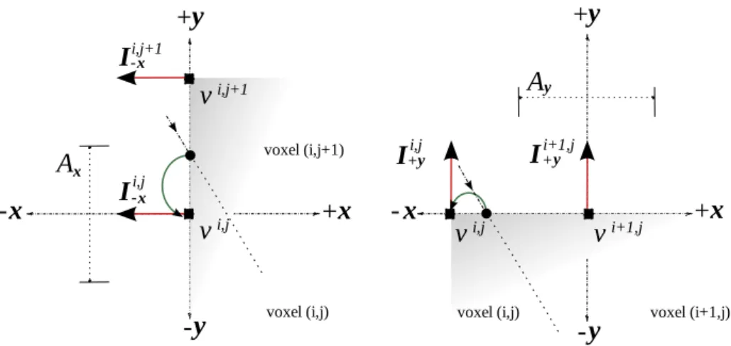
i+1,jFigure 1: Irradiance Vector computation in 2D. When a photon hits a voxel’s face, its contribution is added to the irradiance vector associated with the nearest vertex. Photon contribution added toI−−−i,xxxj(Left) andI++i+,yyyj+1(Right).
from the light sources through the grid. Every time a photon traverses a voxel face, its contribution is added to the irradiance vectorIIIi jk
δ δ
δ associated with the nearest vertexvvv
i jk and the directionδδδprovided by the normal of the face (see Figure 1). When a photon
hits some scene geometry, a classical stochastic reflection is applied according to the local BRDF.
The photon propagation is accomplished in two steps. First, using a ray tracing acceleration structure, we find the closest intersection with the scene. Then, we propa-gate the photon into the Irradiance Vector Grid without any intersection test. Once all photons have been treated, a normalization step is performed on the irradiance vectors:
IIIδi jkδδ = 1 Aδi jkδδ Ni jk δ δ δ X n=1 φnωωωn
whereNδδδi jkis the number of photons that have contributed to the irradiance vector at vertexvvvi jk in directionδδδ, and Ai jk
δ δ
δ is the area of the rectangular cell centered atvvv
i jk in directionδδδ. As we are using a uniform rectangular 3D grid, the area of such cell
is simply the area of the voxel face oriented in the same direction, except for grid boundary vertices, where the area is divided by two, and for grid corner vertices, where it is divided by four.
Note that our approach does not suffer from the classical boundary bias of Photon
Mapping (where spheres with large radii are used to collect photons, such as in room corners and along contours of flat surfaces) as our density estimation correctly accounts for the intersection of the photons with the grid. Unlike the strategy of Havranet al. [HBHS05], our approach does not need to store all the rays generated from the photon propagation.
Volumetric Vector-Based Representation 7
4
Using the Irradiance Vertex Grid
4.1
Interpolation of Irradiance Vectors
In order to compute smooth indirect illumination, we interpolate an irradiance vector for each pointpppwith normalnnnthat needs to be shaded. This interpolation is performed in two successive steps: a spatial interpolation according to pppand then a directional interpolation according tonnn.
In the first step, the irradiance vectorIIIδδδ(ppp) is obtained by spatial interpolation of
the irradiance vectorsIIIi jk
δ δ
δ stored at the grid vertices surrounding pointppp. The
interpo-lation is only done for three out of the six possible directions ofδδδ. The choice between
±x
±x
±x(resp. ±±±yyyand±±±zzz) is done according to the sign ofnx (resp. nyandnz). Trilinear or tricubic interpolation approximate satisfactory smooth results for spatial interpola-tion. In the second step, the final interpolated irradiance vectorIIInnn(ppp) is obtained by remapping the three spatially interpolated irradiance vectors according to the normal directionnnnat pointppp:
IIInnn(ppp)=IIIxxx(ppp)n2x+IIIyyy(ppp)n2y+IIIzzz(ppp)n2z.
4.2
Irradiance Vertex Grid for GPU Rendering
The great benefit of using a 3D regular grid is that the data structure can be straight-forwardly uploaded on GPU as a 3D texture. Then, in the same spirit as environment mapping, precomputed radiance transfer or ambient occlusion fields [KL05], this tex-ture can be used to provide global illumination effects in real-time GPU rendering. In
our case, the interpolated irradiance vectors are simply used by the fragment shader as additional light sources that are meant to encode indirect illumination. Remember that each grid vertex holds one irradiance vectorIIIλper color channel for each of the
sixδδδdirections, i.e., 3×3×6=54 floating point numbers. To reduce the number of
texture fetches which may be costly in current graphics hardware, we compress the 3 irradiance vectors as one color and one direction:
r=kIIIRk g=kIIIGk b=kIIIBk ddd=
IIIR+IIIG+IIIB
kIIIR+IIIG+IIIBk
.
These two vectors are encoded in two 16 bit 3D textures, and therefore the information for the sixδδδdirections require 12 3D textures. To efficiently perform tricubic
interpo-lation in hardware, we adapted the technique of Sigg and Hadwiger [SH05].
4.3
Irradiance Vertex Grid for Software Rendering
Even if it has been initially intended for real-time GPU rendering, the Irradiance Vertex Grid is also interesting in software global illumination environment. As it provides a smooth spatial and directional reconstruction of irradiance vectors, it can be directly used for diffuse indirect illumination, without propagating secondary rays for final
gather. Direct use of cached values could be done using existing techniques [WRC88, KBPv06] but they do not guarantee a continuous reconstruction of the indirect illumi-nation. Moreover, as they do not offer geometry robustness, these techniques require
a large number of samples for highly-detailed geometry, in order to provide accurate estimation.
A final usage of our Irradiance Vector Grid is to be employed as an efficient caching
structure for stochastic approaches. For instance, as done with Photon Mapping, our RR n° 6983
8 Pacanowski&Granier&Poulin&Schlick
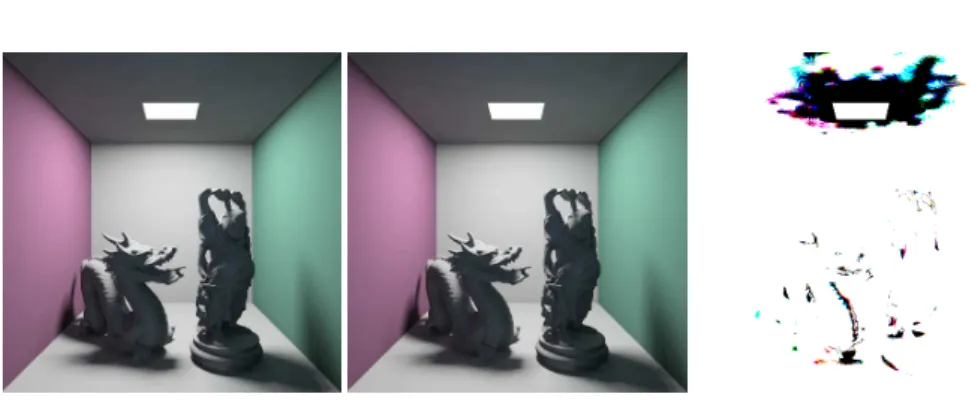
Figure 2: Geometric robustness when using direct access.(Left)The precomputation
is performed in 58son a low detailed geometry (24Ktriangles) and(Center)and in
180shigh detailed geometry (2Mtriangles). (Right)The difference color-coded RGB
image (maximum pixel difference isε=1.5%).
grid may be accessed indirectly by shooting secondary rays from points being shaded. The main advantage is that high-frequency details such as indirect soft shadows are well preserved, and that reconstruction errors are masked since a diffuse or low-glossy
reflection is similar to a low-pass filter [DHS+05]. So, a simple trilinear spatial
inter-polation provides a good compromise between speed and quality.
5
Results
All the results have been computed on an AMD 64bit 3500+processor with 2GB of
memory and a Nvidia 7950 GTX. Images in Figures 4 and 5 have a 640×480
resolu-tion.
5.1
Geometric Robustness
Due to its robustness against geometric details, it is possible with our approach to pre-compute the volumetric irradiance vectors on a low resolution version of the objects, similarly to the approach developed by Tabellion and Lamorlette [TL04]. In Figure 2, the same grid resolution (20×22×20) and the same number of photons (8M) are
used during the precomputation. The resulting illuminations recomputed over the two images are extremely similar, less than 1% maximum pixel difference for a
precompu-tation time divided by three. Changing the geometry refines the curvature of the objects and therefore modifies the photon reflection, explaining the small differences located
on the two objects as well as on the ceiling.
5.2
For GPU Rendering
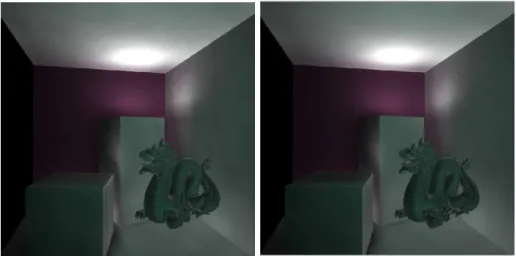
Figure 3 shows the quality and framerates of our reconstruction when using 3D tex-tures on the GPU (at a 600×600 resolution with no antialiasing). We precomputed a
16×16×16 compressed grid (288 KB) without the dragon inside a color modified
Cor-nell box. The two images show the indirect illumination (i.e., interpolated irradiance multiplied by the diffuse albedo) on the whole scene, using either a trilinear (left) or a
tricubic (right) interpolation. This approach is mostly geometry independent since the
Volumetric Vector-Based Representation 9
Figure 3: Indirect illumination on the GPU. The camera and the dragon can be moved at the indicated framerates. (Left)Trilinear interpolation at 91fps. (Right)Tricubic
interpolation at 87 fps.
Precomputation: 201s Precomputation: 252s Rendering: 1,341s (51s) Rendering: 6,618s (5,527s)
Figure 4: Scene with mostly direct illumination case. 16 rays per pixel were used. 5 M photons shot. (Left)Our technique with a 40×50×40 uncompressed grid (24.5 MB)
used directly with a tricubic interpolation scheme. (Center)Photon Mapping with Christensen’s Cache using 50 photons of the 5 M (124 MB) stored where used to pre-compute each irradiance sample.(Right)Reference solution obtained by Path-Tracing with 1600 rays per pixel. The general illumination patterns are similar in all three techniques, however our much faster indirect illumination computation (51s vs. 5527s) strongly reduces the total rendering time (1341s vs. 6618s).
dragon (about 400Ktriangles) can be interactively moved at 90FPS, with a consistent indirect illumination. Note that the complexity is pixel dependent, since the interpo-lation and the lighting evaluation is performed on the fragment stage. The provided video (720x576 resolution rendered with antialiasing) shows another scene with direct and strong indirect lighting configuration.
5.3
For Software Rendering
To evaluate our approach, we present two test scenes with complex lighting. The first configuration (Figure 4) presents a scene mainly directly illuminated from 11 light RR n° 6983
10 Pacanowski&Granier&Poulin&Schlick
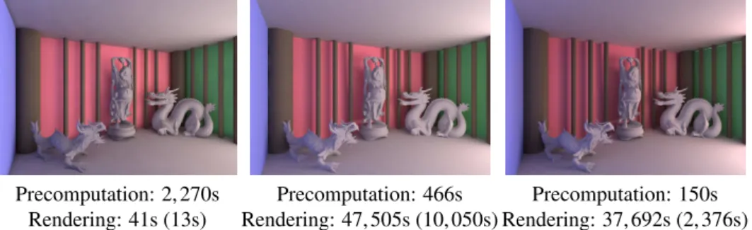
Precomputation: 2,270s Precomputation: 466s Precomputation: 150s
Rendering: 41s (13s) Rendering: 47,505s (10,050s) Rendering: 37,692s (2,376s)
Figure 5: Scene with mostly indirect illumination.(Left)Our technique using directly
a 30×20×92 an uncompressed grid (11.4 MB) constructed with 80 M photons. (Cen-ter)Christensen’s method reference image with 3200 rays to sample the hemisphere
and 5 M photons stored (124 MB).(Right)Our technique using indirectly a 12×8×20
uncompressed grid (590 KB) with the same number of photons shot and the same num-ber of rays to sample the hemisphere.
sources. The second one (Figure 5) is a classical two-room configuration where one room is indirectly illuminated by a light source placed in the other room. Both scenes have more than 8 million polygons due the highly detailed objects. They illustrate the geometric robustness of our approach.
We compare our technique to Photon Mapping combined with Christensen’s [Chr99] precomputed samples. Precomputation time for our technique involves shooting pho-tons and accumulating their contribution in the grid, and for Christensen’s it involves shooting photons, balancing the kd-tree, and precomputing irradiance. For all images generated with Christensen’s method, we set the number of precomputed samples to be one fourth of the total number of photon hits, as originally suggested [Chr99].
Figure 4 compares the results obtained with our technique and Christensen’s for direct lighting configuration. For fair comparison, a reference solution has been com-puted with a high density (1600 rays per pixel) Path-Tracing algorithm. For equivalent precomputation times, our technique allows a much faster computation (51s vs. 5527s) of the indirect component of the illumination due to direct access to the cached val-ues. In our technique, the final gathering step spends most of its time computing ray-geometry intersections and direct illumination, while Christensen’s cache requires to cast a large number of additional gathering rays, since direct access produces very ob-jectionable illumination patterns with zones of constant irradiance similar to Voronoi diagrams. This is a well-known artefact [Chr99] preventing direct access to cached irradiance.
For the indirect lighting configuration presented at Figure 5 we have also tried a direct access to our structure but to capture finer shadows cast by the columns, a higher-resolution grid (30×20×92) was built and consequently a larger number of photons
needed to be shot. This resulted in a much larger precomputation time but our method with direct access is still much faster (2,311s vs. 47,971s) than Christensen’s caching
technique for a similar quality. Alternatively, we have also tested our technique with an indirect access (cf. Figure 5) to the cached values by using a lower resolution grid (12×
8×20) traversed by the same number of photons as with Christensen’s method. Our
technique reduces both precomputation time (150s vs. 466s) and reconstruction time of the indirect illumination (2,376s vs. 10,050s), while retaining similar illumination
Volumetric Vector-Based Representation 11
features. Access time to our grid is constant in the number of the cached samples instead of being logarithmic as with a kd-tree [Chr99, CB04] which explains these gains.
5.4
Discussion
The construction time of our Irradiance Vertex Grid structure grows mainly linearly with the number of photons albeit a small overhead exists when increasing the size of the grid. Note that in Figure 5 (Left) the precomputation time may be reduced by lowering the grid size and shooting less photons. This will lose the high-frequency details but the indirect effect of the light near geometrically complex objects will still
be captured. Noise due to undersampling of the illumination during the shooting pass appears mostly on larger planes and on higher frequency details such as shadows. The quality of the reconstruction directly scales with the number of photon shots, as the illumination details scale with the size of the grid. However, even if un-biased, our estimation can lead to energy leaks or under-estimation of irradiance values, depending on the relative geometric configuration with the grid. These artefacts are reduced by increasing the resolution of the grid. Some of these artefacts may also be reduced by using an adaptive volumetric structure such as an octree, but the structure would be much less efficient when uploaded on the GPU. Finally, it should be mentioned that
our approach cannot reach the reconstruction quality of Ray maps [HBHS05], but as counter part less storage is required.
6
Conclusion
In this report, we have presented a new representation for indirect illumination, based on a 3D grid of irradiance vectors. This representation allows a smooth-everywhere reconstruction of the irradiance. Thanks to the irradiance vectors, the resulting solution is more robust to local variation of geometry, as shown through the presented results.
We have implemented this structure both as a 3D texture texture for indirect illu-mination on the GPU and as a caching scheme for Photon Mapping. The results show that diffuse inter-reflections are well captured. Compared to existing solutions, our
approach requires fewer cached samples for higher-quality cached indirect lighting. Additionally, it does not require any photon storage. Furthermore, our irradiance cache can be directly accessed during the final gathering pass.
Our hardware implementation demonstrates its efficiency for high quality real-time
display of 3D scenes under precomputed global illumination.
Future Work
There are two main improvement directions for our approach. First, the estimation of irradiance vectors is based on a regular grid. Identifying proper resolutions for the grid and the number of photons to shoot requires a good understanding of the illumination effects. A more automatic estimate would facilitate the use of the technique. For large
scenes, we would like to use a multiresolution and adaptive structure in order to reduce the construction cost. This will also allow better capture of indirect illumination near surfaces and maybe find better automatic estimates.
Second since the scheme is based on linear interpolation, some artefacts may appear for complex variations of illumination. The introduction of gradients would improve the smoothness of the reconstruction where incoming illumination varies quickly. Im-proved visibility estimation will also provide higher-quality reconstruction.
12 Pacanowski&Granier&Poulin&Schlick
References
[AFO05] O. Arikan, D.A. Forsyth, and J.F. O’Brien. Fast and Detailed Approximate Global Illumination by Irradiance Decomposition. InProc. SIGGRAPH 2005, pages 1108–1114. ACM, 2005.
[Arv94] J. Arvo. The irradiance Jacobian for partially occluded polyhedral sources. InProc. SIGGRAPH’94, pages 343–350. ACM, 1994.
[CB04] P.H. Christensen and D. Batali. An Irradiance Atlas for Global Illumina-tion in Complex ProducIllumina-tion Scenes. InProc. Eurographics Symposium on Rendering, pages 133–141, 2004.
[Chr99] P.H. Christensen. Faster global photon map global illumination.Journal of Graphics Tools, 4(3):1–10, 1999.
[DBB06] Philip Dutré, Kavita Bala, and Philippe Bekaert. Advanced Global Illumi-nation. A. K. Peters, Ltd., 2006.
[DHS+05] F. Durand, N. Holzschuch, C. Soler, E. Chan, and F.X. Sillion. A frequency
analysis of light transport.ACM Trans. on Graph., 24(3), 2005.
[GSHG92] G. Greger, P. Shirley, P.M. Hubbard, and D.P. Greenberg. Irradiance vol-ume. IEEE Computer Graphics and Applications, 18(2):32–43, 1992. [HBHS05] V. Havran, J. Bittner, R. Herzog, and H.-P. Seidel. Ray Maps for Global
Illumination. InProc. Eurographics Symposium on Rendering 2005, pages 43–54, 2005.
[Jen01] Henrik Wann Jensen. Realistic Image Synthesis using Photon Mapping. A.K. Peters, 2001.
[KBPv06] J. Kˇrivánek, K. Bouatouch, S.N. Pattanaik, and J. Žára. Making radiance and irradiance caching practical: Adaptive caching and neighbor clamp-ing. InProc. Eurographics Symposium on Rendering 2006, pages 127–138, 2006.
[KL05] Janne Kontkanen and Samuli Laine. Ambient occlusion fields. In Proceed-ings of ACM SIGGRAPH 2005 Symposium on Interactive 3D Graphics and Games, pages 41–48. ACM Press, 2005.
[Pha04] M. Pharr.GPU Gems, chapter Ambient occlusion. Addison-Wesley, 2004. [PRG+08] Romain Pacanowski, Mickaël Raynaud, Xavier Granier, Patrick Reuter,
Christophe Schlick, and Pierre Poulin. Efficient Streaming of 3D Scenes
with Complex Geometry and Complex Lighting. InWeb3D ’08: Proc. international symposium on 3D web technology, 2008.
[PRL+08] Romain Pacanowski, Mickaël Raynaud, Julien Lacoste, Xavier Granier,
Patrick Reuter, Christophe Schlick, and Pierre Poulin. Compact Structures for Interactive Global Illumination on Large Cultural Objects. In Interna-tional Symposium on Virtual Reality, Archaeology and Cultural Heritage VAST 2008: Short and Project Paper, 2008.
Volumetric Vector-Based Representation 13
[SH05] Christian Sigg and Markus Hadwiger. GPU Gems 2, chapter Fast Third-Order Texture Filtering. Addison-Wesley, 2005.
[SKJ02] P. Sloan, J. Kautz, and J.Snyder. Precomputed radiance transfer for real-time rendering in dynamic, low-frequency lighting environments. InProc. SIGGRAPH 2002, pages 527–536, New York, NY, USA, 2002. ACM Press. [SSG+00] M. Stamminger, A. Scheel, X. Granier, F. Perez-Cazorla, G. Drettakis, and
F. Sillion. Efficient glossy global illumination with interactive viewing.
Computer Graphics Forum, 19(1):13–25, 2000.
[TL04] E. Tabellion and A. Lamorlette. An approximate global illumination system for computer generated films. ACM Trans. on Graphics, 23(3):469–476, 2004.
[WRC88] G.J. Ward, F.M. Rubinstein, and R.D. Clear. A ray tracing solution for diffuse interreflection. InProc. SIGGRAPH’88, pages 85–92, 1988.
[ZSP98] J. Zaninetti, X. Serpaggi, and B. Péroche. A vector approach for global illumination in ray tracing. InProc. Eurographics 1998, pages 149–158, 1998.
Centre de recherche INRIA Bordeaux – Sud Ouest
Domaine Universitaire - 351, cours de la Libération - 33405 Talence Cedex (France) Centre de recherche INRIA Grenoble – Rhône-Alpes : 655, avenue de l’Europe - 38334 Montbonnot Saint-Ismier Centre de recherche INRIA Lille – Nord Europe : Parc Scientifique de la Haute Borne - 40, avenue Halley - 59650 Villeneuve d’Ascq
Centre de recherche INRIA Nancy – Grand Est : LORIA, Technopôle de Nancy-Brabois - Campus scientifique 615, rue du Jardin Botanique - BP 101 - 54602 Villers-lès-Nancy Cedex
Centre de recherche INRIA Paris – Rocquencourt : Domaine de Voluceau - Rocquencourt - BP 105 - 78153 Le Chesnay Cedex Centre de recherche INRIA Rennes – Bretagne Atlantique : IRISA, Campus universitaire de Beaulieu - 35042 Rennes Cedex Centre de recherche INRIA Saclay – Île-de-France : Parc Orsay Université - ZAC des Vignes : 4, rue Jacques Monod - 91893 Orsay Cedex
Centre de recherche INRIA Sophia Antipolis – Méditerranée : 2004, route des Lucioles - BP 93 - 06902 Sophia Antipolis Cedex
Éditeur
INRIA - Domaine de Voluceau - Rocquencourt, BP 105 - 78153 Le Chesnay Cedex (France)
http://www.inria.fr