Development of TiC based wear resistance
composite coating on AISI 304 steel by
pulsed laser and TIG cladding process
Dissertation submitted in partial fulfillment
of the requirements of the degree of
Doctor of Philosophy
in
Mechanical Engineering
by
Chinmaya Kumar Sahoo
(Roll Number: 513ME1002)
based on research carried out
under the supervision of
Prof. Manoj Masanta
April, 2017
Department of Mechanical Engineering
Department of Mechanical Engineering
National Institute of Technology Rourkela
______________________________________________________________
Certificate of Examination
April 10, 2017
Roll Number: 513ME1002
Name: Chinmaya Kumar Sahoo
Title of Dissertation: Development of TiC based wear resistance composite coating on AISI 304 steel by pulsed laser and TIG cladding process
We the below signed, after checking the dissertation mentioned above and the official record book (s) of the student, hereby state our approval of the dissertation submitted in partial fulfilment of the requirements of the degree of Doctor of Philosophy in Mechanical Engineering at National Institute of Technology Rourkela. We are satisfied with the volume, quality, correctness, and originality of the work.
__________________
Prof. Manoj Masanta
Supervisor
__________________
Prof. Susanta Kumar Sahoo
Member, DSC
__________________
Prof. Anindya Basu
Member, DSC
__________________
Prof. Ashok Kumar Mondal
Member, DSC
__________________
Prof. Siba Sankar Mohapatra
Chairperson, DSC
__________________
Prof. Siba Sankar Mohapatra
Head of the Department
__________________
Department of Mechanical Engineering
National Institute of Technology Rourkela
______________________________________________________________
Dr. Manoj MasantaAssistant Professor
April 10, 2017
Supervisor’s Certificate
This is to certify that the work presented in the dissertation entitled Development of TiC based wear resistance composite coating on AISI 304 steel by pulsed laser and TIG
cladding process submitted by Chinmaya Kumar Sahoo, Roll Number 513ME1002, is a
record of original research carried out by him under mysupervision and guidance in partial fulfilment of the requirements of the degree of Doctor of Philosophy in Mechanical Engineering. Neither this dissertation nor any partof it has been submitted earlier for any degree or diploma to any institute or university inIndia or abroad.
_________________ Manoj Masanta Assistant Professor
Dedication
I would like to dedicate
this dissertation
to
my parents and all my
teachers
Declaration of Originality
I, Chinmaya Kumar Sahoo, Roll Number 513ME1002 hereby declare that this dissertation entitled Development of TiC based wear resistance composite coating on AISI 304 steel by pulsed laser and TIG cladding process presents my original work carried out as a doctoral student of NIT Rourkela and, to the best of my knowledge, contains no material previously published or written by another person, nor any material presented by me for the award of any degree or diploma of NIT Rourkela or any other institution. Any contribution made to this research by others, with whom I have worked at NIT Rourkela or elsewhere, is explicitly acknowledged in the dissertation. Works of other authors cited in this dissertation have been duly acknowledged under the section “Reference”. I have also submitted my original research records to the scrutiny committee for evaluation of my dissertation. I am fully aware that in case of any non-compliance detected in future, the Senate of NIT Rourkela may withdraw the degree awarded to me on the basis of the present dissertation.
April 10, 2017 NIT Rourkela
Acknowledgement
At first, I would like to express my sincere gratitude to my research supervisor Prof. Manoj Masanta for his continuous support and encouragement to complete this research work. This work is polished and presentable due to his valuable suggestion, timely support, and conscientious effort.
I would like to thank Prof. Siba Sankar Mohapatra, HOD Mechanical for constant support and his valuable suggestions as DSC chairman. I am also thankful to Prof. Anindya Basu and Prof. Ashok Kumar Mondal of Metallurgical and Materials Engineering Department and Prof. Susanta Kumar Sahoo of Mechanical Department, for their valuable suggestion and critic evaluation of the research work. I am also grateful to all faculty member of the Department of Mechanical Engineering for their support and valuable advice.
I express my thanks to all technical staffs of the department of Mechanical Engineering and Central workshop for their help in my experimental work. I express special thanks to all staffs of Welding Shop for providing all necessary assistance in conducting TIG cladding experiment. I would like to thank Mr. Subrat Pradhan and Mr. Ch Sivateja
of SEM lab for their help in utilizing SEM facility, Mr. Kasinath Das Mohapatra for wire-EDM, Mr. Sushanta Kumar Sahu and Mr. Bikash Ranjan Moharana for laser processing, Mr. Arabinda Khuntia, Mr. Syamaghan Reddy, and Mr. Somnath Seth of production lab for providing timely help. I also express my gratitude to the Department of Metallurgical and Materials Engineering for providing SEM, XRD, Micro-hardness, Optical microscope facility; Department of Ceramic Engineering for FESEM facility and Department of Chemistry for necessary chemicals and lab facilities. I would also like to acknowledge the financial support provided by DST for procurement of Micro-hardness tester and pin-on-disc wear tester and MHRD for providing scholarship during my Ph.D.
I thank to my co-researcher Jageshwar Kumar Sahu, Tijo D, Lalit Soni,
suggestions to improve the quality of the research work. I am also thankful to one and all who directly or indirectly, supported in my research work.
Apart from my research group, I express my heartfelt thanks to my parents, younger brother
Tanmaya and wife Monalisha for their support and encouragement during my research days. Last but not the least, I thanks to the almighty Lord Jagannath for his blessings.
April 10, 2017 NIT Rourkela
Abstract
TiC is a preferred coating material for the components working under the extreme tribological condition, due to its high hardness, high melting temperature, and low density. In order to improve the hardness and wear resistance properties of stainless steel surface, TiC reinforced coating has been produced on AISI 304 stainless steel using pulsed Nd:YAG laser and Tungsten Inert Gas (TIG) cladding process. Further, to enhance the efficiency of TIG cladding process as well as to amend the tribological properties of TiC based coating, Ni (for better bonding) and CaF2 (as a solid lubricant) have been incorporated in various
phases of experiments. The produced composite coatings are then analyzed by using SEM, FESEM and XRD for microstructural evaluation and phase identification. Micro-hardness value of the produced TiC, TiC-Ni, and TiC-Ni-CaF2 coating has been measured by Vickers
micro-indentation tester and the tribological behavior of the produced coatings have been assessed by sliding abrasive wear test through pin-on-disc wear testing machine. The experimental analysis revealed that TiC reinforced composite coating produced by TIG heat source improved the micro-hardness and abrasive wear resistance significantly. Further, with the incorporation of Ni, bonding between the substrate and TiC reinforcement enhances, and consequently augmented the wear resistance of the coating. In addition, by employing CaF2 with TiC and Ni, the coefficient of friction (COF) of the coating
diminishes, which found become beneficial for the performance of the coating.
Keywords: Hard Coating; TiC-Steel; AISI 304 Steel; Pulsed Nd:YAG Laser; TIG cladding; Solid Lubricants; CaF2
Contents
Certificate of Examination ... i
Supervisor’s Certificate ... ii
Dedication ... iii
Declaration of Originality ... iv
Acknowledgement ... v
Abstract ... vii
List of Figures ... xiii
List of Tables ... xix
Abbreviations ... xxi
Chapter 1 ... 1
Introduction
1.1 Hard and wear resistance coating processes ... 21.1.1 Thermal spray method ... 3
1.1.2 High energy beam method ... 4
1.1.3 Weld deposition methods ... 6
1.2 Mechanism to incorporate the coating materials ... 8
1.2.1 Powder blown method ... 8
1.2.2 Wire feeding method ... 8
1.2.3 Preplaced powder method ... 9
1.3 Classification of hard coating based on coating structure ... 10
1.4 Parameters of Laser and TIG coating/cladding process ... 11
1.4.1 Laser coating parameters ... 11
1.4.2 TIG coating/cladding parameters ... 13
1.5 Substrate material (AISI 304 stainless steel) ... 14
1.6 Ceramic reinforced composite coating ... 15
1.6.1 TiC reinforced composite coating on AISI 304 steel surface ... 16
1.6.2 Bonding material (Ni) ... 16
1.6.3 CaF2 as Solid lubricant ... 16
1.7 Characterization of hard coating ... 18
1.7.1 Coating profile or geometry of the coating ... 18
1.7.3 Compounds or phases present in the coating ...18
1.7.4 Microstructure of the coating ...18
1.7.5 Hardness of the coating ...19
1.7.6 Tribological behavior of the coating ...19
1.8 Coating defects ...20
Chapter 2 ... 23
Literature Review
2.1 TiC composite coating on Ti-6Al-4V ...232.2 TiC composite coating on CP-Ti ...24
2.3 TiC-coating on stainless steel ...25
2.4 TiC reinforced coating on medium carbon steel ...26
2.5 TiC reinforced coating on H13 die steel ...27
2.6 TiC composite coating on Al-alloys ...27
2.7 TiC composite coating on other alloys ...27
2.8 TiC composite coating with other compounds ...28
2.9 TiC-Ni composite coating ...29
2.10 Ni-WC composite coating ...31
2.11 Ni-based composite coating by other methods ...32
2.12 CaF2 as Solid lubricant ...32
2.13 Pulse Laser coating ...34
2.14 TIG coating/cladding ...37
2.15 Self-lubricating coating by TIG cladding ...40
2.16 Research gap and objectives ...43
2.16.1 Objectives ...45
Chapter 3 ... 47
Experimental planning and procedure
3.1 Experimental Planning ...473.2 Substrate material ...48
3.3 Precursor powder use for coating ...49
3.4 Experimental procedure ...49
3.4.1 Substrate preparation ...50
3.4.2 Preplacement of powder mixture ...50
3.4.3 Scanning of heat source for coating ...50
3.4.4 Sample preparation for metallurgical analysis ...53
3.4.6 XRD analysis ... 54
3.4.7 Micro-hardness measurement ... 54
3.4.8 Tribological test ... 54
Chapter 4 ... 57
TiC reinforced composite coating on AISI 304 steel by pulsed laser coating
process
4.1 Introduction ... 574.2 Experimental procedure ... 58
4.3 Result and discussion ... 62
4.3.1 Coating morphology ... 62
4.3.2 TiC-steel composite layer profile ... 67
4.3.3 Micro-hardness ... 74
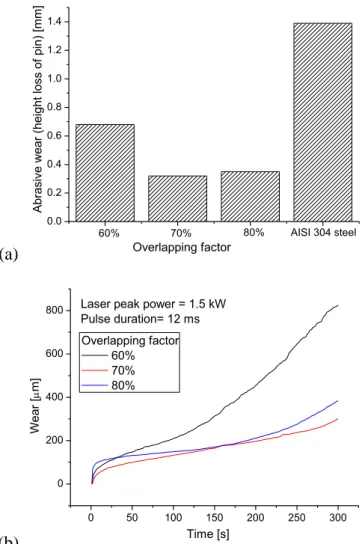
4.3.4 Sliding abrasive wear test ... 77
4.3.5 Coefficient of friction ... 80
4.4 Outcomes ... 81
Chapter 5 ... 83
TiC/TiC-steel composite coating by Tungsten Inert Gas (TIG) cladding
process
5.1 Introduction ... 835.2 Experimental procedure ... 84
5.3 Result and discussion ... 87
5.3.1 Coating morphology ... 87
5.3.2 XRD analysis ... 97
5.3.3 Micro-hardness ... 98
5.3.4 Sliding abrasive wear test ... 100
5.3.5 Coefficient of friction ... 104
5.4 Outcomes ... 105
Chapter 6 ... 107
Deposition of TiC-Ni composite coating on AISI 304 steel by TIG cladding
process
6.1 Introduction ... 1076.2 Experimental procedure ... 108
6.3 Results and discussion ... 111
6.3.1 Microstructural analysis ... 111
6.3.3 Sliding abrasive wear ...118
6.3.4 XRD analysis ...121
6.3.5 Comparison between TiC and TiC-Ni coating ...122
6.3.6 Worn-out coating morphology ...126
6.3.7 Coefficient of friction ...129
6.4 Outcomes ...130
Chapter 7 ... 131
Effect of CaF2 content on TiC-Ni-CaF2 composite coating produced by
TIG cladding process
7.1 Introduction ...1317.2 Experimental procedure ...133
7.3 Results and discussion ...135
7.3.1 Coating profile ...136
7.3.2 XRD analysis ...141
7.3.3 Micro-hardness ...143
7.3.4 Microstructural analysis ...144
7.3.5 Sliding abrasive wear ...154
7.3.6 Morphology of worn surface ...157
7.3.7 Coefficient of friction ...162 7.4 Outcomes ...164
Chapter 8 ... 165
Conclusions
8.1 Major conclusions...165 8.2 Major contributions ...1688.3 Future scope of the present work ...169
References ... 171
Dissemination ... 185
xiii
List of Figures
Fig. 1.1: Classification of hard coating methods ... 3
Fig. 1.2: Schematic diagram of laser coating by powder blow method ... 4
Fig. 1.3: Schematic diagram of shield metal arc deposition process ... 6
Fig. 1.4: Schematic diagram of TIG cladding process ... 7
Fig. 1.5: Schematic diagram of powder blow method used in laser coating ... 8
Fig. 1.6: Schematic diagram of wire feeding method using laser beam ... 9
Fig. 1.7: Schematic diagram of coating by preplacing method using laser beam as heat source ... 9
Fig. 1.8: Basic parameters for coating powder employment in laser and TIG cladding .... 10
Fig. 1.9: Schematic diagram of alloying, dispersing and cladding process ... 11
Fig. 1.10: Laser processing parameters affecting coating process ... 12
Fig. 1.11: TIG coating/cladding processing parameters affecting coating process ... 14
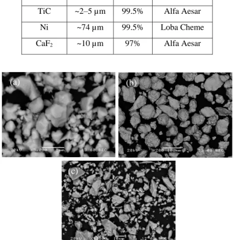
Fig. 3.1: SEM images of (a) TiC, (b) Ni, (c) CaF2 powders ... 49
Fig. 3.2: Pulse Nd:YAG laser system for laser coating process ... 51
Fig. 3.3: Schematic diagram of laser surface modification process using pulse laser ... 51
Fig. 3.4: Schematic diagram of TIG cladding process ... 52
Fig. 3.5: Images of (a) TIG torch fitted with linear moving trolley (b) top view of experimental setup for TIG cladding process ... 53
Fig. 3.6: Single track coating and pin cut by wire-EDM for wear test ... 53
Fig. 3.7: Schematic diagram of the pin-on-disc experimental setup ... 55
Fig. 3.8: (a) Pin on Disc wear test rig, (b) abrasion wear test of coated pin against Al2O3 abrasive disc, (b) adhesion wear test of coated pin against harden steel counter part ... 55
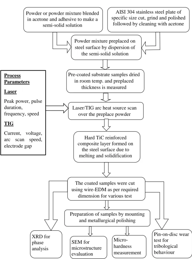
Fig. 3.9: Flow chart of laser or TIG cladding ... 56
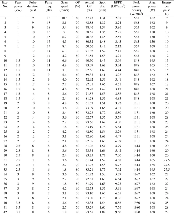
Fig. 4.1: SEM images at the cross-section of TiC-steel composite layer produced by pulse Nd:YAG laser with peak power = 1 kW, pulse duration = 10 ms with overlapping factor of (a) 60% (b) 70% and (c) 80% ... 64
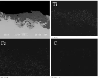
Fig. 4.2: EDS elemental mapping of laser coated zone corresponding to Fig. 4.1(b) ... 64
Fig. 4.3: SEM images at the cross-section of TiC-steel composite layer produced by pulse Nd:YAG laser with peak power = 1.5 kW, pulse duration = 12 ms with overlapping factor of (a) 60% (b) 70% (c) 80% ... 65
Fig. 4.4: SEM images at the cross-section of TiC-steel composite layer produced by pulse Nd:YAG laser with peak power =2 kW, pulse duration = 12 ms with overlapping factor of (a) 60% (b) 70% (c) 80% ... 66
xiv
Fig. 4.5: SEM images at the cross-section of TiC-steel composite layer produced by pulse Nd:YAG laser with peak power = 3 kW, pulse duration = 9 ms with overlapping factor of (a) 60% (b) 70% (c) 80% ...66 Fig. 4.6: SEM images at the cross-section of TiC-steel composite layer produced by pulse Nd:YAG laser with overlapping factor of 80% and (a) peak power = 1 kW, pulse duration =10ms (b) peak power = 1.5 kW, pulse duration = 12 ms (c) peak power = 2 kW, pulse duration= 12 ms (d) peak power = 3 kW, pulse duration = 9 ms ...67 Fig. 4.7: SEM images at the cross-section of TiC-steel composite layer produced by pulse Nd:YAG laser with peak power = 2 kW, overlapping factor = 80%, pulse duration (a) 10 ms (b) 12 ms and (c) 14 ms ...67 Fig. 4.8: Maximum depth of TiC-steel composite layer on steel substrate against different overlapping factor for different laser peak power and pulse duration condition processed with pulse Nd:YAG laser ...68 Fig. 4.9: Maximum depth of TiC-steel composite layer on steel substrate against laser peak power for different overlapping factor and pulse duration condition processed with pulse Nd:YAG laser ...69 Fig. 4.10: Maximum width of TiC-steel composite layer on steel substrate against different overlapping factor for different laser peak power and pulse duration condition processed with pulse Nd:YAG laser ...70 Fig. 4.11: Maximum width of TiC-steel composite layer on steel substrate against laser peak power for different overlapping factor and pulse duration condition processed with pulse Nd:YAG laser ...71 Fig. 4.12: Average micro-hardness value of TiC-steel composite layer produced by pulsed Nd:YAG laser at different overlapping factor, pulse duration and peak power condition .75 Fig. 4.13: Average micro-hardness value of TiC-steel composite layer produced by pulsed Nd:YAG laser at different peak power condition for different pulse duration and overlapping factor ...76 Fig. 4.14: (a) Abrasive wear or height loss of pin (b)wear behavior (height loss of pin against time) during wear test of the laser coated samples produced with peak power of 1.5 kW, pulse duration of 12 ms and overlapping factor of 60, 70, and 80% ...78 Fig. 4.15: SEM micrograph of the worn surface of TiC coated pin produced by laser coating process with peak power 1.5 kW, pulse duration 12 ms and pulse to pulse overlapping factor of (a) 60%, (b) 70% and (c) 80% ...79 Fig. 4.16: Variation in coefficient of friction (against harden steel, HRC 58) of (a) TiC coating produced at peak power of 1.5 kW, pulse duration of 12 ms and overlapping factor of 80% (b) AISI 304 steel ...80 Fig. 5.1: Schematic diagram of Tungsten Inert Gas (TIG) cladding process ...86 Fig. 5.2: Schematic diagram of the pin-on-disc experimental setup ...87 Fig. 5.3: SEM images of the cross-section of TiC coating produced by TIG cladding method with 60 A current, and scan speed of (a) 4.1 mm/s, (b) 5.3 mm/s and (c) 6.5 mm/s ...88
xv
Fig. 5.4: SEM images of the cross-section of TiC coating produced by TIG cladding method with 80 A current, and scan speed of (a) 4.1 mm/s, (b) 5.3 mm/s and (c) 6.5 mm/s ... 88 Fig. 5.5: SEM images of the cross-section of TiC coating produced by TIG cladding method with 100 A current, and scan speed of (a) 4.1 mm/s, (b) 5.3 mm/s and (c) 6.5 mm/s ... 89 Fig. 5.6: Variation of coating layer depth against arc scanning speed for different processing current ... 89 Fig. 5.7: Variation of coating layer width against arc scan speed for different TIG current ... 90 Fig. 5.8: Magnified FESEM image of the TiC coating processed with 60 A current and 6.5 mm/s arc scan speed, corresponding to Fig. 5.3c ... 90 Fig. 5.9: EDS elemental mapping of the dark zone of the coating layer corresponding to SEM image shown in Fig. 5.8 ... 91 Fig. 5.10: High magnified FESEM micrograph of the coating prepared with 60 A current and scan speed of (a) 4.1 mm/s, (b) 5.3 mm/s and (c) 6.5 mm/s ... 94 Fig. 5.11: High magnified FESEM micrograph of the coating prepared with 80 A current and scan speed of (a) 4.1 mm/s, (b) 5.3 mm/s and (c) 6.5 mm/s ... 94 Fig. 5.12: High magnified FESEM micrograph of the coating prepared with 100 A current and scan speed of (a) 4.1 mm/s, (b) 5.3 mm/s and (c) 6.5 mm/s ... 94 Fig. 5.13: XRD pattern of TiC coating on AISI 304 stainless steel substrate processed by TIG cladding with scan speed of 6.5 mm/s and different current ... 97 Fig. 5.14: Average micro-hardness of the coating produced at different current and scan speed ... 98 Fig. 5.15: Variation of abrasive wear (height loss) for the TIG coated samples processes at different current and scan speed condition, after sliding wear test ... 101 Fig. 5.16: Sliding abrasive wear behavior or height loss against the time elapsed during wear test of the TIG coated samples processed with current of (a) 60 A, (b) 80 A and (c) 100 A and different scan speeds ... 102 Fig. 5.17: SEM images of the coated surface after sliding abrasive wear test, produced with scan speed of 6.5 mm/s and current of (a) 60 A, (b) 80 A and (c) 100 A ... 104 Fig. 5.18: Coefficient of friction (against harden steel, HRC 58) of TiC coating produced by TIG cladding process with 60 A current and 6.5 mm/s scan speed ... 104 Fig. 6.1: Schematic diagram of TIG cladding process ... 110 Fig. 6.2: Schematic diagram of pin-on-disc sliding abrasive wear test set-up ... 110 Fig. 6.3: FESEM micrographs at the cross-section of TiC-Ni coated AISI 304 steel sample produced by TIG cladding process with scan speed of 5.3 mm/s and current (a) 40 A, (b) 50 A, (c) 60 A, (d) 80 A ... 112 Fig. 6.4: FESEM micrographs at the cross-section of TiC-Ni coated AISI 304 steel sample produced by TIG cladding process with scan speed of 6.5 mm/s and current (a) 40 A, (b) 50 A, (c) 60 A, (d) 80 A ... 112
xvi
Fig. 6.5: High-magnified FESEM images corresponding to marked portion of Fig. 6.3 i.e. TiC-Ni coating prepared by TIG cladding process with scan speed of 5.3 mm/s and current (a) 40 A, (b) 50 A, (c) 60 A, (d) 80 A ...113 Fig. 6.6: High-magnified FESEM images corresponding to marked portion of Fig. 6.4 i.e. TiC-Ni coating prepared by TIG cladding process with scan speed of 6.5 mm/s and current (a) 40 A, (b) 50 A, (c) 60 A, (d) 80 A ...113 Fig. 6.7: EDS elemental mapping of the TiC-Ni coating produced with 50 A current and 6.5 mm/s scan speed by TIG cladding process ...115 Fig. 6.8: EDS elemental mapping of the dark zone of the coating produced at 40 A current and 5.3 mm/s scan speed (corresponding to Fig. 6.5a) ...115 Fig. 6.9: High magnified FESEM image and corresponding EDS mapping of TiC-Ni coating produced by TIG cladding process with 80 A current and 5.3 mm/s scan speed ...116 Fig. 6.10: Average micro-hardness value of TiC-Ni coating produced by TIG cladding process with different current and scan speed ...118 Fig. 6.11: Variation of sliding abrasive wear of TiC-Ni composite coating specimen processed at different TIG current and processing speed against Al2O3 abrasive disc ...119
Fig. 6.12: Sliding abrasive wear behavior (height loss against time) of TiC-Ni coated steel samples produced by TIG cladding process with different current and arc scan speed of (a) 5.3 mm/s and (b) 6.5 mm/s ...120 Fig. 6.13: XRD pattern of TiC-Ni composite coating surface produced on AISI 304 steel by different TIG current (40, 60 and 80 A) and scan speed of 6.5 mm/s ...121 Fig. 6.14: Variation of micro-hardness value of TiC-Ni and TiC coating produced by TIG cladding process at different current for scan speed of (a) 5.3 mm/s and (b) 6.5 mm/s ...124 Fig. 6.15: Variation of abrasive wear (height loss) of TiC-Ni and TiC coating produced by TIG coating process at different current for scan speed of (a) 5.3 mm/s and (b) 6.5 mm/s ...125 Fig. 6.16: SEM micrograph showing the worn surface (at different magnification) of TiC-Ni coating processed at 40 A and 6.5 mm/s ...127 Fig. 6.17: SEM micrograph showing the worn surface (at different magnification) of TiC coating processed at 60 A, 6.5 mm/s ...127 Fig. 6.18: SEM micrograph of the worn surface of (a) TiC-Ni coating produced with 80 A current and 6.5 mm/s scan speed (b) TiC coating 100 A current and 6.5 mm/s scan speed ...128 Fig. 6.19: Coefficient of friction (against harden steel, HRC 58) of TiC-Ni coating produced by TIG cladding process with 40 A current and 6.5 mm/s scan speed ...129 Fig. 7.1: Schematic diagram of TIG cladding process ...134 Fig. 7.2: SEM images of the cross-section of TiC-Ni-CaF2 composite coating produced by
TIG cladding process using 5wt.% CaF2 in the precursor and welding current of (a) 60 A
xvii
Fig. 7.3: SEM images of the cross-section of TiC-Ni-CaF2 composite coating produced by
TIG cladding process using 10wt.% CaF2 in the precursor and welding current of (a) 60 A
(b) 80 A and (c) 100 A ... 136 Fig. 7.4: SEM images of the cross-section of TiC-Ni-CaF2 composite coating produced by
TIG cladding process using 15wt.% CaF2 in the precursor and welding current of (a) 60 A
(b) 80 A and (c) 100 A ... 137 Fig. 7.5: SEM images of the cross-section of TiC-Ni-CaF2 composite coating produced by
TIG cladding process using 20wt.% CaF2 in the precursor and welding current of (a) 60 A
(b) 80 A and (c) 100 A ... 137 Fig. 7.6: Variation of (a) maximum coating thickness and (b) width of the TiC-Ni-CaF2
coating produced by TIG cladding for single line scan with different current and CaF2
percentage in the precursor ... 138 Fig. 7.7: XRD pattern of TiC-Ni-CaF2 coating produced with different percentage of CaF2
in the precursor by TIG cladding process performed at (a) 60 A, (b) 80 A and (c) 100 A current ... 142 Fig. 7.8: Average micro-hardness value of TiC-Ni-CaF2 coating produced by TIG cladding
process with different current and CaF2 percentage in the precursor ... 144
Fig. 7.9: Magnification SEM image correspond to Fig 7.2 of TiC-Ni-CaF2 produced with
precursor coating 5wt.% CaF2 and processing current of (a) 60 A, (b) 80 A, (c) 100 A . 147
Fig. 7.10: Magnification SEM image correspond to Fig 7.3 of TiC-Ni-CaF2 produced with
precursor coating 10 wt.% CaF2 and processing current of (a) 60 A, (b) 80 A, (c) 100 A
... 147 Fig. 7.11: Magnification SEM image correspond to Fig. 7.4 of TiC-Ni-CaF2 produced with
precursor coating 15wt.% CaF2 and processing current of (a) 60 A, (b) 80 A, (c) 100 A 148
Fig. 7.12: Magnification SEM image correspond to Fig. 7.5 of TiC-Ni-CaF2 produced with
precursor coating 20wt.% CaF2 and processing current of (a) 60 A, (b) 80 A, (c) 100 A 148
Fig. 7.13: Microstructure of TiC-Ni-CaF2 produced with precursor coating 5wt.% CaF2 and
processing current of (a) 60 A, (b) 80 A, (c) 100 A ... 150 Fig. 7.14: Microstructure of TiC-Ni-CaF2 produced with precursor coating 10wt.% CaF2
and processing current of (a) 60 A, (b) 80 A, (c) 100 A ... 150 Fig. 7.15: Microstructure of TiC-Ni-CaF2 produced with precursor coating 15wt.% CaF2
and processing current of (a) 60 A, (b) 80 A, (c) 100 A ... 151 Fig. 7.16: EDS mapping of coating formed using 10 wt.% CaF2 powder system processed
using 60 A current ... 151 Fig. 7.17: High magnification image of coating for 5wt.% CaF2 system produced using 60
A current ... 152 Fig. 7.18: EDS elemental analysis of the microstructure of the coating produced with 15 wt.% CaF2 in the precursor and current of (a) 60 A and (b) 80A ... 153
Fig. 7.19: Variation in abrasive wear (height loss) of the TiC-Ni-CaF2 coated pin for using
xviii
Fig. 7.20: Variation in wear behavior of TiC-Ni-CaF2 coated pin produced with different
percentage of CaF2 in the precursor and current of (a) 60 A, (b) 80 A and (c) 100 A ...156
Fig. 7.21: SEM images (at different magnification) of the worn out TiC-Ni-CaF2 composite
coating surface (after sliding abrasive wear test) produced at 60 A current, for using (a–b) 5wt.% (c–d) 10wt.% and (e-f) 15wt.% CaF2 in the precursor ...158
Fig. 7.22: SEM micrographs (at different magnification) of the worn out TiC-Ni-CaF2
composite coating surface (after sliding abrasive wear test) produced at 80 A current, for using (a–b) 5wt.% (c–d) 10wt.% and (e-f) 15wt.% CaF2 in the precursor ...159
Fig. 7.23: SEM image and corresponding EDS analysis of the worn out surface for the coating produced with 80A current and precursor containing (a) 5% CaF2 (b) 15% CaF2
...161 Fig. 7.24: SEM micrographs (at different magnification) of the worn out TiC-Ni-CaF2
composite coating surface (after sliding abrasive wear test) produced at 100 A current, for using (a–b) 5wt.% (c–d) 10wt.% and (e-f) 15wt.% CaF2 in the precursor ...162
Fig. 7.25: Variation in coefficient of friction (against harden steel, HRC 58) of TiC-Ni-CaF2
coating produced at (a) 60 A and (b) 100 A current for using different percentage of CaF2
xix
List of Tables
Table 1.1: Properties of some metallic carbides used as hard and wear resistance coating ... 15 Table 1.2: Physical properties of Ni and CaF2 ... 17
Table 1.3: Various types of wear testing methods ... 19 Table 2.1: Different coating material used to improve surface property by TIG coating process ... 41 Table 3.1: Composition of AISI 304 stainless steel ... 48 Table 3.2: Properties of AISI 304 stainless steel ... 48 Table 3.3: Specification of TiC, Ni, CaF2 powders ... 49
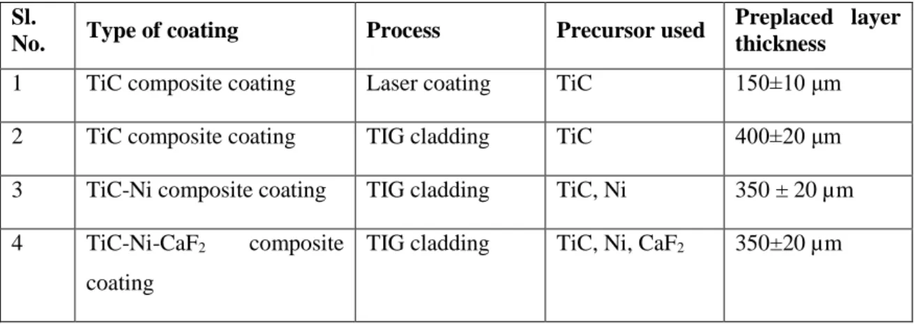
Table 3.4: Precursor mixture for producing TiC reinforced composite layer on AISI 304 steel ... 50 Table 3.5: Specification of pulsed Nd:YAG laser system ... 51 Table 3.6: TIG processing conditions ... 53 Table 4.1: Experimental condition for laser coating of TiC on AISI 304 steel ... 60 Table 4.2: Condition for pin-on-disc type sliding abrasive wear test ... 62 Table 4.3: EDS analysis for the selected region corresponding to Fig. 4.15 ... 79 Table 5.1: Experimental condition for TIG cladding process ... 86 Table 5.2: Detail experimental condition for Tungsten Inert Gas cladding process ... 86 Table 5.3: Sliding abrasive wear test condition by pin-on-disc wear test rig ... 87 Table 5.4: EDS analysis showing wt.% of elements present in the entire region of FESEM images corresponding to Fig.5.10-5.12 ... 95 Table 5.5: Local hardness value for the selected coating consisting non-uniform morphology ... 100 Table 6.1: TIG processing conditions ... 110 Table 6.2: Experimental table for TIG cladding ... 110 Table 6.3: Operating condition for Pin-on-disc type sliding abrasive wear test ... 111 Table 7.1: Experimental condition to produce TiC-Ni-CaF2 coating on AISI 304 steel by
TIG cladding ... 134 Table 7.2: Condition for pin-on-disc type sliding abrasive wear test ... 135 Table 7.3: Sliding test condition for measurement of COF ... 135 Table 7.4: EDS elemental analysis of marked position corresponding to Fig. 7.17 ... 152 Table 7.5: EDS analysis of TiC-Ni-CaF2 coating produced with 15wt.% CaF2 in the
precursor and current of 60 and 80 A, as marked in Fig. 7.18 ... 153 Table 7.6: EDS analysis of the marked region corresponding to Fig. 7.23 ... 161
xxi
Abbreviations
BSE: Backscatter ElectronCOF: Coefficient of Friction CP: Commercially Pure
CVD: Chemical Vapour Deposition DAS: Data Acquisition System DMLS: Direct Metal Laser Sintering
EDS: Energy-dispersive X-ray spectroscopy EPPD: Effective Peak Power Density
FESEM: Field Emission Scanning Electron Microscope GTA: Gas Tungsten Arc
GTAW: Gas Tungsten Arc Welding LENS: Laser Engineered Net Shaping MMC: Metal Matrix Composite PLD: Pulsed Laser Deposition PPD: Peak Power Density PTA: Plasma Transfer Arc
PVD: Physical Vapour Deposition SAW: Submersed Arc Welding SEM: Scanning Electron Microscope SMAW: Shield Metal Arc Welding TIG: Tungsten Inert Gas
1
Chapter 1
Introduction
Mechanical failure of machine components or elements leads to an enormous loss in the industry in term of economy and accidental hazard. Mechanical failure can be avoided by selecting the proper material and appropriate manufacturing process or by augmenting the lifespan of the components by various surface modification techniques i.e. surface hardening, shot peening or application of hard coating (Zikin et al., 2013). Hard coating methods like electroplating, PVD, CVD, thermal spraying, laser coating/cladding, weld cladding are successfully used to deposit a hard layer on the surface of a component. These coating methods with suitable coating materials enable to improve the tribological and corrosion resistance property of a material and enhance the life of a component. A coating should have characteristics like excellent bonding with the substrate, suitable layer thickness, and improved mechanical property like high hardness, wear resistance, toughness, and corrosion resistance, in combination with low coefficient of friction, resistance to thermal shock, and stability at high temperature (Jiang and Molian, 2001). These characteristics of the coating primarily depend on the properties of the coating material and the process involved. Further, the performance of the coating also influenced by the compatibility between the coating and substrate material in terms of mechanical, thermal and metallurgical properties. Therefore, selection of appropriate coating material and process to fabricate a reliable and defect-free coating with superior performance are the key challenges (Berger, 2015).
It is fairly acceptable that with the development of new superalloys, the performance of a component enhances due to their high strength to weight ratio, high corrosion resistance, and high-temperature resistance compared to the conventional structural materials. However, owing to relatively low hardness and wear resistance these newly developed superalloys are also not sufficient to perform in adverse environmental condition. On the other hand, refractory ceramics possesses high melting temperature, excellent hardness, and superior abrasive and adhesive wear resistance compared to the metal or alloy. Therefore, these ceramic particles are suitable candidate as a coating material for superior performance. Nevertheless, the low fracture toughness of the brittle ceramic cause failure in the coating by formation of cracks or delamination from the substrate surface. Brittle
2
ceramic particles combined with ductile metal can produce metal matrix composite (MMC) coating on the substrate surface that enable to provide superior hardness, wear resistance along with high toughness. The ceramic reinforced metal matrix composites are usually used for wear resistance components (Du et al., 2011). The MMC can withstand high tensile and compressive stress by distributing the applied load between the matrix and reinforced phases (Huang et al., 2003). The ceramic-reinforced MMC material exhibits superior performance characteristic at high-temperature application, due to high melting temperature of ceramic reinforcement (Emamian et al., 2012a). Nevertheless, making an entire component with reinforced ceramic become uneconomical, when the volume of the component become extremely large. Application of a hard coating layer or reinforcement of hard particles on the surface of the component can enhance its performance. Furthermore, it is well accepted that incorporation of solid lubricant in the coating may reduce the frictional force or coefficient of friction value of the surface during sliding wear and consequently reduces the wear rate of the component. Therefore, fabrication of a hard and wear resistance ceramic reinforced MMC coating in combination with solid lubricant is greatly needed. Furthermore, a suitable coating technique that enables to produce a reliable and defect-free coating at low cost is also indispensable. Tungsten inert gas (TIG) cladding or alloying is an emerging and low-cost coating method widely used for fabrication of hard-facing of metallic substrates, where an improved surface layer is produced by melting the powder or powder mixture preplaced on a substrate surface.
1.1 Hard and wear resistance coating processes
Hard and wear resistance coating usually fabricated on metallic substrate by using different type of coating or surface modification technique i.e. PVD, CVD, PLD, thermal spray coating, high energy beam methods like laser cladding/alloying, electron beam alloying, and weld deposition methods i.e. tungsten inert gas (TIG) cladding, shielded metal arc weld (SMAW) cladding, etc. Detail classification of different types of hard coating techniques is illustrated in Fig. 1.1. Among these processes, PVD, CVD, PLD are used for fabrication of thin coating. In contrast, to produce a thick coating, thermal spray, high energy beam methods like laser coating/electron beam coating and weld deposition methods are utilized (Pawlowski, 1999). A brief discussion on different type coating process used to deposit a thick layer of hard coating illustrated below.
3
Fig. 1.1: Classification of hard coating methods
1.1.1 Thermal spray method
Among various thermal spray methods, plasma spray and high velocity oxy fuel (HVOF) are popular to deposit hard and wear resistance coating uniformly and at faster rate. In plasma spray coating, the plasma flame fully/partially melts the feed stock powder and spray at high velocity towards the substrate surface. The high velocity molten powder stick on the substrate surface and produce a uniform and thick coating layer (Pfender, 1988). In HVOF method, the combustion product from specially designed torch carries the feedstock powder at high velocity and impinge on the substrate surface to form a coating layer. The hard metal or ceramic powder deform (splat) due to high velocity impact of the powder on the substrate surface (Cetegen and Basu, 2009). The thermal spray methods are economical, reliable and repeatable and produce a coating with minimum distortion of substrate material. However, the produced coating by plasma spray method comprise high volume of porosity, low chemical homogeneity and suffering from weak bonding between the coating and substrate. These defects in the coating deteriorates the corrosion and wear resistance of the coating (Chen et al., 2014; Mateos et al., 2000; Singh et al., 2007).
Hard coating Thick coating Thermal spray Plasma transfer arc HVOF/HVAF Vacuum plasma spraying High energy beam Laser cladding Laser alloying Electron beam alloying Weld deposition TIG coating SMAW coating SAW coating Thin coating PVD CVD Electroplating PLD
4
1.1.2 High energy beam method
(i) Electron beam alloying/coating
High energy of the electron beam can be utilized for surface modification of various heat resistive material through surface melting or surface alloying. The electron beam melts the preplaced powder and substrate surface to produce a modified coating layer. The electron beam coating has successfully utilized to produce coating layer using hard ceramic materials (Dong et al., 2003). Nevertheless, application of electron beam alloying is limited due to high equipment cost, complex control system and requirement of vacuum during the coating process.
(ii) Laser coating
Laser coating method is one of the state of art method to produce a hard ceramic coating on the substrate. A defocused and moving laser beam act as a heat source to melt the feedstock (sprayed powder) or preplaced powder material and deposited on the substrate surface as a coating layer (Weng et al., 2014). The laser beam power and scan speed controlled in such a way that it only melt the preplaced or sprayed powder and the surface of the substrate material and produces a metallurgical bond between the coating material and the substrate with low dilution (mixing) of coating material (Nowotny et al., 2014). The laser coated surface possess superior surface property like wear resistance, corrosion resistance, hardness compared to the substrate material. For laser coating, both continuous and pulsed mode laser beam can be used. Fig. 1.2 shows the schematic diagram of laser coating process by co-axial powder blown method. Depending on the mechanism or mixing ratio the process is called laser coating/cladding or alloying.
Fig. 1.2: Schematic diagram of laser coating by powder blow method
Powder spray
Nozzle with powder feed system
Substrate Coating
Laser beam
5
There are several advantages of the laser coating process those made it most popular coating technique to deposit various type of hard coating on versatile of substrate materials (Emamian et al., 2012a, 2012b; Jiang and Molian, 2001; Katipelli et al., 2000a). Some of the specific advantages of the laser coating process are listed below
Laser coating/cladding can deposit a thick layer on the substrate surface.
Due to occurrence of fusion in the coating material and substrate surface, a strong metallurgical bond obtained.
In case of laser cladding, minimum dilution of the coating material with the substrate is possible, which enable to produce a unique coating as per the requirement.
In laser coating process heat affected zone (HAZ) on the base material is minimum that maintains the base material properties.
High cooling rate during solidification in laser coating process, induces fine grain microstructure, which improves the mechanical and metallurgical property of the coating.
Irrespective of the above advantages, application of laser coating process restricted in small scale industry due to the following drawbacks (Candel et al., 2010).
High initial and running cost of laser setup.
Non-uniform heat distribution in Nd:YAG and CO2 laser.
The absorptivity of laser beam is very less for metal that diminishes the efficiency of the process.
Laser coating though powder blow method is highly complex, due to the involvement of a large number of processing parameters.
It is worth to mention that regardless of the above limitation laser coating or cladding have successfully used in various engineering application as follows (Emamian et al., 2012a; Jiang and Molian, 2001; Katipelli et al., 2000a; Nowotny et al., 2014):
To repair worn-out surface of turbine blade and other mechanical component
To improve the life of rolling mills, casting dies by depositing hard coating layer.
To deposit wear resistance coating on large scale drill-bit rigs and other earth removal equipment used in mining industries.
6
1.1.3 Weld deposition methods
(i) Shielded metal and gas metal arc deposition
In this method, shielded metal or gas metal arc welding setup is used, where the consumable electrode material deposited as a coating layer. The electrode material usually different from the substrate material and having superior mechanical properties. The electrode material melted due to the heat generation from arc and deposited on the substrate surface. A thick coating can be produced by depositing the molten electrode material overlapped after each track and layer by layer (Wang et al., 2008). The coating material can also be supply through continuous wire feeding like MIG welding. Shielded metal or gas metal arc deposition is an economical coating process, commonly used for repair work and to produce hard and wear resistance overlay coating for the components used in mining industry. However, uncontrolled heat supply causes high dilution of the coating material with substrate and sometime damage the substrate surface. Further, manufacturing of different type hard electrode or wire is highly challenging. Fig.1.3 demonstrate the schematic diagram of shield metal arc deposition process.
Fig. 1.3: Schematic diagram of shield metal arc deposition process
(ii) GTAW or TIG coating/cladding
GTAW or TIG welding is a fusion welding method usually used to join metallic plates. A non-consumable tungsten electrode used, and the arc is generated between the electrode and work piece, which melt the junction of the metallic plates to be join and after solidification a sound weld joint obtained. In TIG coating/cladding process, the arc is used as a heat source to melt the coating material as well as the substrate surface by moving it through a track on the substrate. The coating material applied either by powder preplacing on the substrate surface prior to the scanning of the arc or by blowing powder or feeding a wire during the scan of the arc. Fig 1.4 shows the schematic diagram of TIG cladding process. The TIG cladding is an economical coating process compared to the laser coating, plasma spraying
Substrate
Coating Electrode filler rod or
Electrode holder
Melted coating material
7
or other high-energy coating methods used to deposit hard and wear resistance coating. Employing the preplaced powder, TIG coating process successfully utilized to deposit a coating with hard ceramic particles i.e. TiC, WC, SiC or their composites. The ceramic reinforced composite coating produced by TIG cladding possesses high hardness and wear resistance. The performance of the coating depends on the TIG processing parameters like current, voltage, scan speed, gap between electrode and work surface, and coating materials. Both continuous and pulsed mode of power supply are used as heat source.
Fig. 1.4: Schematic diagram of TIG cladding process
Some of the basic advantages of TIG cladding process are illustrated below (Mridha et al., 2015; Patel et al., 2014)
The process is highly economical compared to laser, plasma or HVOF coating due to low cost of the TIG welding set-up.
By controlling the parameters either a thick coating of ceramic or ceramic reinforced metal matrix composite coating can be produced.
Excellent adhesion between the coating and substrate material is possible due to strong metallurgical bonding.
Different type of coating material in the form of powder can be employed to produce a hard, wear resistance and corrosion resistance coating surface.
Apart from the above advantages TIG cladding process has specific limitations as described below
High heat input may damage the substrate material.
High dilution of the coating material with substrate compared to laser coating process.
Powder blown method sometimes interrupts the arc stability.
Non-uniform heat distribution of TIG arc causes inhomogeneity in the coating. Substrate Coating Electrode scan direction Preplaced powder Tungsten electrode Shielding gas
8
1.2 Mechanism to incorporate the coating materials
To produce a thick layer, coating material usually deposited either by powder blown method or preplaced powder method. Apart from these, coating material sometimes also supplied through wire feeding mechanism. Different coating material feeding methods are briefly illustrated below
1.2.1 Powder blown method
In powder blown method, the substrate surface is melted by using either laser beam or TIG arc heat source and simultaneously fine powder of coating material (mainly ceramic particles or mixture of ceramic and metal powder) blown to the molten zone through a nozzle. An inert carrier gas is used to flow the powder and maintain its flow rate. During the coating process the blown powder partially or fully melted and deposited on the substrate surface to produce a thick coating layer. For laser cladding, sometimes a coaxial nozzle is used that provide very precise control on the melting and deposition of the powder. Fig. 1.5 illustrate the schematic diagram of the coating by powder blown method using laser beam as a heat source.
Fig. 1.5: Schematic diagram of powder blow method used in laser coating (Sahoo et al., 2015)
1.2.2 Wire feeding method
In this method, the coating material to be deposited supplied in the form of wire. The laser or TIG heat source melted the wire and deposited it on the substrate surface. Wire feeding method is highly efficient compared to powder spray and preplaced powder method, due to minimum loss of coating material. However, the precision alignment between the heat source and coating wire is necessary for any defect free coating. Fig. 1.6 shows the schematic diagram of the coating by wire feeding method utilizing laser beam as a heat source. Laser beam Powder supply system Coating Substrate v
9
Fig. 1.6: Schematic diagram of wire feeding method using laser beam (Sahoo et al., 2015)
1.2.3 Preplaced powder method
Fig. 1.7: Schematic diagram of coating by preplacing method using laser beam as heat source (Sahoo et al., 2015)
Preplaced powder method is a two steps process. In the first step, the powder or powder mixture to be coated is preplaced on the substrate surface. In the next step, the heat source i.e. laser beam or TIG arc scan over the preplaced powder layer. The high energy heat source melts the powder as well as a thin layer of the substrate to produce the coating. The powder pre-placement is one of the commonly applied methods due to its simplicity and requirement of low quantity powder for the coating. The preplacement of the coating material may be done in the form of dry powder, slurry, paste, strip, sheet, wire (Farnia et al., 2013a). The powder is usually mixed with an organic binder and applied on the substrate surface as paste. Sometimes, preplacement of the coating material also done by thermal spray method, and in next phase TIG arc or laser beam is used to re-melt the pre-deposited coating to produce a sound bond between the coating and substrate material (Ghadami et al., 2015; Mateos et al., 2000). Preplaced powder method is limited to produce a coating on a flat surface only and overlapping scan is required to make a large area coating surface (Farnia et al., 2013a; Paital et al., 2011). Fig. 1.7 represent the schematic diagram of the coating process by powder pre-placement method using laser beam as a heat source.
Laser beam Wire feed system Coating Substrate v Laser beam Preplaced powder layer Coating Substrate v
10
Basic parameters considered for the employment of coating powder in laser based and weld based coating process, which govern the performance of the final coating are illustrated in Fig. 1.8
Fig. 1.8: Basic parameters for coating powder employment in laser and TIG cladding
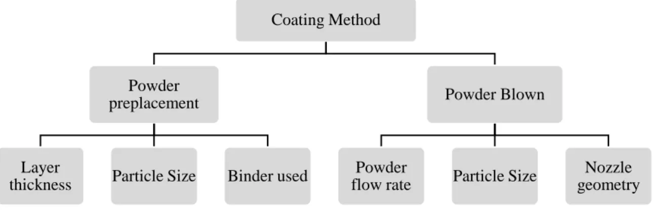
1.3 Classification of hard coating based on coating structure
The thick coating process like thermal spray coating, laser coating, and weld deposition can be further classified based on the degree of mixing of the coating material with the substrate. It has been already described that thermal spray method like HVOF, plasma spray methods melt only the coating material and no dilution with the substrate. However, in laser coating or TIG coating/cladding process both the powder and substrate surface melted. Therefore, depending upon the degree of mixing of the coating and substrate material, and based on the characteristic of the coating material, the hard coating process can further categorize as surface alloying, dispersing or cladding. Fig. 1.9, show the schematics of surface alloying, dispersing and cladding.In surface alloying, full dissolution of the coating material in substrate surface occurred. The coating material mixed with the substrate material in molten state and form an alloy. The produced alloy surface improve the surface property of the substrate. The alloyed layer may have different properties than the applied coating material or substrate. Fig. 1.9a shows that both coating material (y) and the surface of the substrate (x) melted and mixed in the melt pool. The solidified surface layer produces an alloy containing both the coating and substrate materials. In dispersion method, the substrate surface melted by laser beam or TIG arc heat source, and the coating material in the form of small particles dispersed in the molten surface. Commonly, hard ceramic particles like TiC, WC, Al2O3 are
Coating Method
Powder preplacement
Layer
thickness Particle Size Binder used
Powder Blown
Powder
flow rate Particle Size
Nozzle geometry
11
used as dispersing element to produce a coating with superior mechanical properties than the substrate. After solidification, coating and substrate material remain unchanged and can be identified separately. Fig. 1.9b shows the schematic diagram of dispersion method. In the cladding process, the heat input controlled precisely to obtain minimum dilution of the coating material with the substrate surface. In this method, coating material produces a separate layer on the substrate surface. The properties of the clad layer are independent of the substrate material, whereas in alloying and dispersion method the substrate material has significant influence on the produced coating. Fig. 1.9c shows the schematic of cladding process.
Fig. 1.9: Schematic diagram of alloying, dispersing and cladding process
1.4 Parameters of Laser and TIG coating/cladding process
In laser and TIG coating/cladding, structure and quality of the coating mostly depend on the rate of heat input, cooling rate, material properties. The heat input to the coating can be controlled by selecting appropriate processing parameters. Detail of parameters for laser and TIG coating process are described below.1.4.1 Laser coating parameters
In laser coating process, a de-focused laser beam is scanned over the pre-deposited coating surface on the substrate material to obtain almost uniform heat distribution on the track profile. The laser beam with the interaction of preplaced coating surface produces heat, which completely or partially melts the coating layer and substrate surface to produce a strong coating on the substrate.
The parameters affecting the heat input in the processed zone mainly depends on the type of laser, wavelength of laser beam, laser power, beam diameter, scan speed, absorptivity of the coating material, and for pulse type laser, pulse duration, and frequency. Fig. 1.10 shows the laser processing parameters affecting the coating process.
Substrate (x) x+y
Substrate (x)
External material (y) x
Substrate (x)
External material (y) x+y
Surface alloying Dispersing Cladding
12
Fig. 1.10: Laser processing parameters affecting coating process
Heat supply by the laser beam during coating process depend on the mode of laser operation i.e. continuous or pulsed. In continuous mode of laser beam, energy per unit length can be calculated as
H = P S⁄ … Eqn (1.1)
Where, H is energy per unit length; P and S are laser power and scan speed respectively (Hong et al., 2015). Power density or energy per unit area (laser power/beam area) also used as input parameter to represent the heat input.
(i) Pulse Laser coating
Although, continuous wave laser is extensively used for laser surface modification, owing to specific advantages of pulse laser such as high peak power controlled pulse duration, frequency, and pulse energy, the use of pulse laser for surface modification become an emerging area of research (Yan et al., 2010a).
However, there is a lack of study about employing the pulsed laser in surface modification, mainly due to its discontinuous behavior and lower processing capability. During pulse laser operation, laser beam energy is delivered through intermittent pulses, which can be controlled by pulse duration, frequency of pulses, and pulse energy. This allows more precise regulation of spatial and temporal modes of laser beam energy delivery, which could create different thermal condition, microstructures, and phases within the laser substrate interaction region, which is not possible for samples processed with a continuous laser (Farnia et al., 2013a). Again, due to short pulse width and high peak power, pulse laser could produce sufficient higher melting depth as well as substantially higher cooling rate in the melt pool than that of continuous laser processing. The laser power-off period between two pulses, allows the melt pool to solidify and the higher cooling rate could be obtained by pulsed laser processing and corresponding microstructure produced more
Laser Parameters for coating Mode of operation Continuous Pulse Laser power Beam dia/Area Beam scan speed Beam wavelength Pulse duration (for pulsed mode) Pulse frequency (for pulsed mode)
13
refined. Since hardness and other mechanical property of a particular material depend on the characteristic of the microstructure, therefore coated or alloyed zone produced by a pulsed laser should have superior mechanical property than that of produced by a continuous laser (Sun et al., 2005).
In pulsed laser, processing parameter like laser peak power, pulse duration, pulse frequency, scanning velocity are considered to calculate the heat input. Heat input per pulse and total heat input during the pulsed laser processing are described by peak power density and effective peak power density (EPPD) respectively (Ghaini et al., 2007; Lapsanska et al., 2010).
General observation states that laser input parameters have significant effect on the performance of the produced coating i.e. hardness and wear resistance. Owing to variation in the degree of mixing of the coating material with the substrate or due to difference in the melting and cooling rate, microstructure of the coating get altered. Consequently, the mechanical properties of the coating changed accordingly.
1.4.2 TIG coating/cladding parameters
In TIG coating/cladding process depending on the heat input, the degree of melting of the substrate decided and produces either a separate layer of coating material or a mixed metal matrix composite layer. Heat input during the TIG coating process can be control by regulating the electrode scan speed and input power i.e. voltage and current.
The heat input in the TIG process can be calculated by using equation 1.2.
H = η(V. I/S) …Eqn. (1.2)
Where V, I and S represent the voltage, current and scan speed respectively; η is heat absorption efficiency (Mridha et al., 2012a). The equation shows that the heat input is directly proportional to the current and voltage, and inversely proportional to arc scan speed. In addition, tool electrode gap, electrode diameter, gas flow rate, type of shielding gas are also affecting coating process and the properties performance of the produced coating. Patel et al. (2014) found that shielding gas has great influence on the temperature rise along the coating track. The melt pool or coating thickness also affected by the substrate temperature prior to coating (Mridha et al., 2015). Fig.1.11 shows the TIG processing parameters affecting the quality of the coating.
14
Fig. 1.11: TIG coating/cladding processing parameters affecting coating process
1.5 Substrate material (AISI 304 stainless steel)
Stainless steel is one of the primary choices for manufacturing of machine components, utensils, structural elements, due to its high strength, corrosion resistance (Akhtar and Guo, 2008). AISI 304 stainless steel have superior mechanical property and high corrosion resistance in adverse environment. Hence, AISI 304 stainless is widely used in structural applications, equipment associated with the chemical and nuclear power industries, food processing industry, petrochemical industry, condenser tubing, vapour lines tubing and heat exchangers (Majumdar et al., 2007; Singh et al., 2012; Majumdar and Manna, 1999). However, application of the austenite steel limited for the components those are directly involved in abrasive and adhesive wear environment i.e. mining and agricultural equipment chutes, rock excavator teeth, tool and dies in the manufacturing industry. The hardness of stainless steel can be improved by addition of carbon; however, reduction in ductility of steel may affect its overall performance (Ushashri and Masanta, 2015). Heat treatment process also not suitable for austenite steel to increase its surface hardness because during heat treatment the carbon and Cr in steel combined and formed chromium carbide (Cr23C6)
along the grain boundary (McGuire, 2008). Lack of Cr in the steel consequently reduce the corrosion resistance of steel. Addition of hard ceramic particles like TiC, SiC, and WC on the austenitic steel surface may produce a composite clad layer that makes the steel component resistive against wear by improving its hardness. So far, different coating techniques were employed to deposit hard and wear resistance coating on various type of steel substrate (Masanta et al., 2011; Piasecki et al., 2016; Ramírez et al., 2015; Yang et al., 2014). TIG Cladding parameters Mode of cureent Continu ous Pulsed
Current Voltage Scan speed
Electrode
Dia Shrouding gas
Stand- of-distance Frequency (for pulse) Duty cycle (for Pulse)
15
1.6 Ceramic reinforced composite coating
Ceramic particle reinforced metal matrix composites (MMCs) retaining high hardness, strength, stiffness and wear resistance compared to its matrix base, along with preeminent toughness than the monolithic ceramic or ceramic composites (Emamian et al. 2012b). However, it was revealed that fabrication of an entire MMC component sometimes uneconomical due to its manufacturing complexity and high cost of reinforced ceramic particles (Yan et al., 2012). It is worth to mention that a layer of ceramic particle reinforced MMC on the base material surface produced by high energy density deposition methods like laser cladding/alloying, thermal spraying, TIG melting/cladding can improve the surface properties of the component without affecting its bulk characteristics (Berger, 2015).
Hard ceramic materials like carbides (WC, TiC, SiC, VC, and Cr3C2), oxides (Al2O3,
ZrO2), borides (TiB2, SiB3, SiB6) are widely utilized as reinforced or coating material to
produce metal matrix composite (MMC). Among these, TiC is one of the eminent carbide used as reinforced particle in various type of metal matrix due to its high hardness, high melting temperature, and low density. TiC can retain its hardness at elevated temperature, which makes it most promising coating material for the high-temperature application (Rasool and Stack, 2014). TiC reinforced coating, further preferred in tribological application due to its low frictional coefficient, thermodynamic stability, high elastic modulus (Rajabi et al., 2015). Table 1.1 shows some of the physical properties of TiC along with other carbides normally used as reinforcement in MMC. It was reported that WC reinforced Co based MMC is most widely use coating material. However, its oxidation and corrosion resistance are lower than that of TiC (Candel et al., 2014).
Table 1.1: Properties of some metallic carbides used as hard and wear resistance coating (Ariely et al., 1991; Li et al., 2011; Groover, 2007)
Metallic-Carbides Hardness Density (g/cm3) Melting
temperature (oC) TiC 3000 HV 4.93 3067 SiC 2600 HV 3.2 2700 WC 2600 HV 15.6 2870 VC 2800 HV 5.77 2810 Cr2C3 18.9 GPa 6.68 1895
16
1.6.1 TiC reinforced composite coating on AISI 304 steel surface
Poor wear resistance of AISI 304 steel surface can be improved by using hard TiC reinforced metal matrix composite coating. This type of MMC coating can be produced by using laser coating/cladding or TIG coating/cladding process. TiC possesses high hardness (3000 HV) compared to steel (200 HV) and has limited solubility with Fe (Ariely et al., 1991). Therefore, TiC reinforced particles can be reinforced in steel during the coating process without forming any intermetallic. TiC-steel MMC coating provides superior surface properties than the steel substrate. The effort of several research groups revealed that TiC reinforced coating on AISI 304 steel significantly improved the surface hardness, fretting and sliding wear resistance compared to the as received steel surface (Akhtar and Guo, 2008; Ayers and Tucker, 1980; Rasool et al., 2015; Ushashri and Masanta, 2015). Further, TiC-steel composite coating reduces the coefficient of friction and wear rate for a wide range of load and sliding speed (Peng, 2012). Moreover, TiC reinforced steel coating can be produced by both ex-situ and in-situ methods using high energy density heat sources like laser beam or TIG arc. The above discussion revealed that stainless steel is a suitable matrix material for TiC reinforced particles to improve its hardness and wear resistance.
1.6.2 Bonding material (Ni)
It is relevent to mention that major challenges associated with the fabrication of TiC reinforced steel composite coating is to attain proper interfacial bonding, as the solubility of TiC in steel is very low and frequently produces undesirable intermetallic compounds (Man et al. 2002). It is worth to mention that to obtain an appropriate bond between the substrate and the reinforced ceramic particles, interfacial materials like Ni and Co; those are retaining high wetting property with both TiC particles and steel matrix need to provide (Nowotny et al. 2014). It is well established that for thermal spray process, these interface materials produces a separate layer between the substrate and the ceramic coating with a minimum dilution (Pawlowski 1999). Table 1.2 illustrate the physical properties of Ni used as a bonding material between TiC and steel.
1.6.3 CaF2 as Solid lubricant
It is well accepted that apart from the hard coating, employment of appropriate lubrication can also improve the lifetime of a component by reducing the frictional force between the moving parts. It has been observed that conventional liquid or semi-solid lubricants do not
17
work efficiently under vacuum, high load and extreme temperature condition (very high/low) (Liu et al., 2013). The solid lubricant is an alternate solution that effectively used in various components where the application of conventional lubricant is unjustified. Earlier, noble metal like gold and silver were commonly used as solid lubricants (Jin et al., 1999). However, the high cost of these metals is the major constraint in their application for regular use. Recent studies indicate that organic alkali fluorides (LiF2, CaF2, BaF2),
disulfides (MoS2, WS2), and some metal oxides (Zr2O3, Cr2O3, MoO3) are good aspirants as
solid lubricants (Liu et al., 2013). Among these, alkali fluorides are preferred due to their low density, low shear strength, stable thermos-physical and thermos-chemical properties at higher temperature in conjunction with their low cost and ease of availability (Xiao-feng et al., 2009).
CaF2 is a well-known and widely used solid lubricant, normally utilized in
self-lubricating ceramic composite and anti-wear applications. CaF2 has a laminar structure with
low shear strength, which prevent the adhesion wear and assist in tribo-chemical reaction to facilitate a reduction in wear. Additionally, it is chemically stable at high temperature and does not react with reinforced materials. Furthermore, due to low hardness and slip plane structure, CaF2 easily soften to act as a lubricant. It is also used as fluxing medium and
enhances fluidity of the melt-pool (Yan et al., 2012). CaF2 can transform from brittle to
ductile at higher temperature (600 oC) by forming low shear strength ductile phase (Wang
et al., 2002). Table 1.2 demonstrate the physical properties of CaF2.
Table 1.2: Physical properties of Ni and CaF212
Properties Ni CaF2
Melting point 1453 oC 1403 oC
Thermal expansion coefficient 13.4 ×10⁻⁶ (°C-1) 18.18 ×10⁻⁶ (°C-1)
Thermal conductivity 90.9 W/(m·K) 9.71 W/(m·K)
Density 8.9 g/cm³ 3.18 g/cm3
Crystalline structures FCC Hexagonal
1 Calcium Fluoride ( CaF2 ), Fluorite or Fluorospar - Properties and Applications, accessed
24 October 2016, <http://www.azom.com/article.aspx?ArticleID=2352>.
2 Nickel(Ni)- Properties, Applications, accessed 24 October 2016,