The Segment Routing Architecture
Clarence Filsfils
∗, Nagendra Kumar Nainar
∗, Carlos Pignataro
∗, Juan Camilo Cardona
†, Pierre Francois
∗ ∗Cisco Systems, Inc.
†
IMDEA Networks Institute / UC3M
Abstract—Network operators anticipate the offering of an increasing variety of cloud-based services with stringent Service Level Agreements. Technologies currently supporting IP networks however lack the flexibility and scalability properties to realize such evolution. In this article, we present Segment Routing (SR), a new network architecture aimed at filling this gap, driven by use-cases defined by network operators. SR implements the source routing and tunneling paradigms, letting nodes steer packets over paths using a sequence of instructions (segments) placed in the packet header. As such, SR allows the implementation of routing policies without per-flow entries at intermediate routers. This paper introduces the SR architecture, describes its related ongoing standardization efforts, and reviews the main use-cases envisioned by network operators.
I. INTRODUCTION
Traditionally, traffic steering within service provider net-works was primarily based on an IP lookup at each router lying on the path towards the destination. The underlying Interior Gateway Protocol (IGP) protocol was used to distribute the topology information and calculate the shortest paths to be followed from the ingress to the egress node. In the last decade, the dependence of many businesses on network performance and availability became increasingly relevant. Strict Service Level Agreements (SLA) in terms of packet loss, delay, jitter, and available bandwidth became a key business differentiator. These requirements drove network evolution towards architec-tures allowing for steering traffic with more flexibility.
In the 90s, the MPLS architecture introduced a powerful tun-neling mechanism and a traffic steering functionality, modeled on the ATM/FR architecture [1]. The tunneling functionality was fundamental for the success of the MPLS technology, notably through the support of IP/MPLS-based VPNs [1]. The traffic steering model, based on the Resource reSerVa-tion Protocol - Traffic Engineering (RSVP-TE) faces several challenges, which make it harder for operators to implement and Operate: First, the poor balancing characteristics of the RSVP-TE model do not fit the true nature of IP, which is based on networks offering abundant Equal-Cost Multi-Paths (ECMP). To overcome this fundamental incoherence, a notorious number of MPLS RSVP-TE tunnels need to be replicated, thus elevating the difficulty of managing and monitoring the network [2]. With SR, traffic can be steered using forwarding constructs, which benefit from ECMP, so that a single SR tunnel configuration can capture a set of paths. Second, control-plane and data-plane scalability issues are caused by the state required at each hop along any explicit path. While operators already expressed their concern on such scaling issues [3], it is anticipated that this situation would be amplified for merged networks offering a large portfolio
of services.Third, the RSVP-TE deployment model observed until now is based on distributed computation. This leads to unpredictable placement of the traffic, non-optimal use of the resources, and slow re-optimization [4].
In a context where networks evolve towards application-centric platforms, operators now require more flexible, yet scalable, and simple to operate network architectures. The aforementioned limitations make unfeasible for RSVP-TE to support those strict and dynamic environments.
The IETF started works on standardizing an architecture aimed at fulfilling these requirements, called Segment Routing (SR) [5][6][7]. SR is a source routing based tunneling tech-nique that allows a host or an edge router to steer a packet through the network by using a list of segments. A segment is an identifier for a topological instruction (steering the packet over a given path) or a service instruction (delivering the packet to a service).
Because the information of the path that the packet has to traverse is included in the packet, intermediate routers do not have to maintain state for all steered paths that the network offers. Additionally, as a shortest-path segment includes all the ECMP paths to the related node, SR supports the ECMP nature of IP by design. These two features provide drastic gains in network scalability.
The SR architecture can leverage both distributed and cen-tralized network control paradigms to provide efficient network solutions. The distributed intelligence of the network is used to build these segments, re-optimize them upon any network topology change, and pre-compute 50msec backup path against link or node failures. The centralized intelligence can trust the network to provide the basic building blocks and solely focus on service resource optimization by expressing optimum end-to-end paths. Especially for the dynamic environments envi-sioned for virtualized network services and cloud applications, SR provides a flexible interface to the network infrastructure, without compromising network resources and scale.
In this document, we present the SR technology. We de-scribe the standardization effort to support the framework, and provide a list of use cases driving this effort. The paper is structured as follows. In Section II, we provide an overview of the SR architecture. We describe several of the use-cases that motivated the development of SR, and how the technology can support them in Section III. We close with a short discussion on the perspectives for future research in SR and conclusions in Sections IV and V, respectively.
II. SEGMENTROUTINGARCHITECTURE
Fig. 1. Sample network topology.
different components of the architecture must be defined. First, the data-plane of SR defines how to encode the sequence of segments to be applied on a packet, and the forwarding semantics of segments (how each device should process a packet based on a segment). The described operation of SR is agnostic to the actual protocol used to carry the information of the SR header.
Second, thecontrol-planeof SR defines how segment iden-tifiers are spread among the network devices, and how network devices are instructed to apply a given sequence of segments on a flow.
A. SR data-plane
From an abstract point of view, a SR header contains a sequence of segments, and a pointer to the active segment of the packet, being the instruction that needs to be executed by the device processing the packet. When the active segment has been executed, the following segment on the list becomes the active one. A segment ID (SID) is an identifier for a segment. Depending on its type, a SID can have domain wide significance or can be significant only locally to the router processing it.
The main types of segment are the next:
• Node SID: The forwarding semantic associated with Node SID is to forward the packet on the shortest path towards the Node associated with that Segment ID. The operator assigns a domain wide unique Node segment ID for each router in the network. This can be done manually or using a centralized controller.
• Adjacency SID: The forwarding semantic associated with an Adjacency SID is to forward the packet over the corresponding adjacency. Each router will assign a locally significant segment ID for each of its IGP adjacencies.
• Service SID: The forwarding semantic associated with a Service SID is to deliver the packet to the corresponding service provided by the node processing the packet. Each node will assign a locally significant segment ID for each service that it provides to the network.
An SR-enabled node supports the following data-plane operations:
• CONTINUE - Forwarding action performed based on active segment.
• PUSH - Add a segment ahead of the SR header of the packet and set that segment as the active segment.
• NEXT - Mark the next segment as the active segment. In our reference topology depicted in Figure 1, each router is assigned a Node SID. For instance, router R2, R3, and PE5 are assigned Node SIDs 9002, 9003, and 9010, respectively. For the links, R2 assigns the Adjacency SID 2023 for its adjacency to R5 using Link A, and SID 2032 for link B. The rest of adjacency SIDs are omitted for clarity, but each device could assign one for each available adjacency.
PE1 can reach PE5 by simply using Node SID 9010 in the SR header. The flows of packets towards PE5 will be
load-balanced over the shortest paths to PE5, as defined by the IGP.
PE1 could enforce the path via R2, by executing a PUSH operation to set the segment list to 9002, 9010. The packet will be sent to R3, as per the meaning of Node SID 9002. R3 performs a normal CONTINUE operation on this SID, forwarding the packet to R2. When R2 receives a packet with the segment list 9002, 9010, 9002 (itself) being the active segment, it moves the pointer to the next segment (NEXT), 9010, and forwards the packet towards R3.
The router can also require the packet to flow over the path R2-R5-R6-PE5, moving between R2 and R5 using link A. If this were the case, PE1 would instead use the segment list 9002, 2023, 9010. When R2 receives the packet, it moves the pointer to next segment, which is 2023, which identifies the instruction to perform a NEXT operation and forward over link A. The packet will reach R5 with active segment 9010. Shortest path forwarding proceeds from there on to the destination.
Note that the level of flexibility in path definition achieved from the source router without keeping additional state in routers R2 and R3, as it would be required with RSVP-TE. This additional state could be considered irrelevant for this example, but has proven to be difficult to cope with for ISP networks that may require the definition of multiple thousands of service chains in their network.
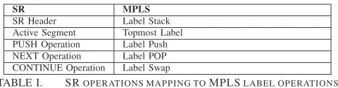
From a concrete point of view, operators are free to choose the SR data-plane technology that they want to deploy based on their network requirements. MPLS and IPv6 are the two data-plane technologies currently considered for SR support, as these are the typical data-planes for such networks:
SR MPLS
SR Header Label Stack Active Segment Topmost Label PUSH Operation Label Push NEXT Operation Label POP CONTINUE Operation Label Swap
TABLE I. SROPERATIONS MAPPING TOMPLSLABEL OPERATIONS.
MPLS. SR can seamlessly be applied to MPLS data-plane with minimal or no hardware changes [8]. Table I provides the mapping of the SR operations to MPLS label operation.
IPv6. With the tremendous interest from the industry in migrating to a native IPv6 data-plane, there are various En-terprise and Managed Service Providers, such as data centers, which can leverage the benefits of SR without the need of an MPLS implementation. Authors propose a new IPv6 Extension Header to encode the SR header in [9]. We depict the currently proposed format for the header in Figure 2.
Fig. 2. IPv6 header for SR [9].
B. SR control-plane
Fig. 3. Sample network for service chaining and traffic engineering use cases.
The extensions of IGP protocols would allow any router to maintain a database of all nodes and adjacency segments. Also, by leveraging the sub-second convergence properties of both IGPs, the segment database on each router can be quickly updated after any topology change. Note that using these extensions, end-to-end encapsulation can be performed in the network without requiring enabling and management of another protocol, such as LDP.
Another element of the control-plane of SR deals with how an ingress router is instructed to select the SR path that a packet should follow. The following methods can be used for this purpose:
1) Distributed Constrained SPF (CSPF) calculation.In this approach, an ingress router calculates the shortest path for a destination, under the constraint that this path matches some criteria. It then computes a sequence of node and adjacency segments that encodes this path. 2) SDN controller based approach.SR provides a
scal-able and resilient data-plane while allowing the flexi-bility of control commonly assumed for SDN environ-ments. This aspect led to the planned support of SR into designs of some SDN oriented controllers. For example, OpenDaylight supports the control of SR using the Path Computation Element Protocol (PCEP) [12].
3) Statically defined by the operator.Static configuration of the tunnels might be used for specific purposes such as testing or troubleshooting, but it is typically not recommended for network operation in the long term, due to evident scaling, resiliency, and management limitations.
An operator can choose any of these methods, based on the applications and scenarios that they want to support. Note that the three strategies can coexist in the same network. Static tunnels could be used for troubleshooting or specific, but infre-quent, purposes. The CSPF method provides a balance between connectivity optimization and automation. The great flexibility delivered by centralized approaches makes it compelling for networks with TE objectives for which conflicting decisions could be taken when performed in a distributed way (e.g. demand placement for capacity engineering purposes).
III. SEGMENTROUTING USE CASES
In this section, we describe various use cases that can leverage SR to obtain maximum benefit.
A. Traffic Engineering using SR Tunnels
Nowadays, networks support a variety of applications, with their respective constraints on how resources are used to serve them. It is prevalent for service providers to ensure that traffic flows transported between same devices, with different resource requirements, follow optimal, maybe dissimilar paths. SR can give control over traffic-engineered paths without increasing control-plane overhead at the transit nodes.
We use the network topology of Figure 3 to illustrate how traffic engineering can be implemented with SR. Let us
consider 2 types of application traffic entering the domain via PE1 that should be processed by the Deep Packet Inspection (DPI) service function before egressing the domain: Voice service and high demanding bandwidth service. Voice traffic should be steered over a short latency path, which is PE1-R1-R2-LinkB-R5-PE3-DPI. Large bandwidth flow should be steered over high bandwidth path PE1-R1-R2-LinkA-R5-PE3-DPI.
For the voice traffic, PE1 would place the segment list
{9002, 2032, 9008, 1002} in the SR header, and forward to R1. Note that since a Node SID instructs a device to forward a packet using the shortest paths to a destination, PE1 does not require to define the path hop-by-hop. After receiving the packet, R1 will perform a CONTINUE operation on the SR header, forwarding the packet to R2. R2 will forward the same to R5 via LinkB, which in turn will forward to PE3. PE3 will forward to the DPI service function for packet processing.
For the case of large bandwidth application traffic, PE1 would push a SR header with segment list{9002, 2023, 9008, 1002}, and forward it to R1. When the packet reaches R2, it forwards the packet to R3 using link A, as instructed by the SID 2023. The process continues until PE5 receives the packet. Note that usually, the SP network will be engineered for capacity on shortest IGP paths, so that large BW application traffic only needs to be steered in tactical short-term situations. Compared to a distributed approach, a centralized controller based SR TE instantiation can offer more predictable and efficient solutions, thanks to the complete visibility of the topology and traffic demand matrix of the network. It can also react in a scalable manner to path failures and manipulate routing policy without any compromise on SLA. By simulating the centralized controller approach on many operator use cases, we observed that the number of SR TE tunnels to be injected to comply with SLA constraints, and re-optimization of such tunnels during failures, led to much less signaling overhead when compared to the distributed RSVP-TE based approach. [13] reports reductions of up to an order of magnitude in the state maintained in routers for 10 different topologies by using SR instead of RSVP-TE. Furthermore, studies have shown that only a few segments are required to obtain optimal traffic distributions: [13] obtains traffic distribution close to the ones of RSVP-TE using only 2 labels. Independently, [14] also informs that two segments were required to achieve solutions close to the theoretically optimal ones.
B. Service Function Chaining
Recently, a group of operators and manufacturers proposed an architecture in which many of the functions of these applications are virtualized. The proposal, denominated Net-work Function Virtualization (NFV), is gaining popularity and promises to be a key element in future networks [15]. Although NFV would provide operators with more control on implementing network functions, operators still lack a way to apply these functions into their network in a flexible and main-tainable manner. For this purpose, a technique denominated Service Function Chaining (SFC) was proposed [15]. SFC eliminates the constraint associated with physical topology based service function, by instantiating a Service Function Path, which is an ordered list of service functions in the packet header. Since SR already provides a similar framework, it becomes a suitable candidate to implement SFC on existing MPLS and IPv6 data-planes.
We will illustrate the use of SR for service functions using the topology of Figure 3. The operator managing the network in the figure would like to apply a set of services, in a fixed order, for any traffic between R1 and R4:
1) Apply Firewall policy.
2) Apply Deep Packet Inspection.
SR defines service segments, as the instruction to apply a given service on a packet. Service segments have local significance to each device. Therefore, a service segment is typically combined with a node segment that ensures delivery to the service node. In our sample topology, the service segments are defined as follows:
• PE4 will assign{1002}for a Firewall service
• PE3 will assign{1003}for a DPI service function To apply the service chain, PE1 will push a SR header with segment list{9009, 1003, 9008, 1002, 9010}and forward the packet. PE4 will receive the packet and use the next segment, 1002, to identify the service function for packet processing. After PE4 receives the packet back from the Firewall service, it will forward the packet to PE3, based on the top SID 9008. PE3 will forward the packet to the DPI service and then forward the packet to R6. R6 will then forward the packet towards its final destination.
C. Segment Routing based Network Resiliency
To achieve strict SLAs, operators must rely on robust recov-ery mechanisms that can protect the reachability of destinations against sudden network component failures, in a guaranteed amount of time. A typical service restoration time requirement is 50ms after failure. Such stringent requirements lead to a distributed, local approach to provide resiliency, supported by the router itself.
Fast ReRoute (FRR) mechanisms, which prepare the data-plane of a router for a fast-forwarding state switchover upon failure detection, were commonly used to achieve this goal. No additional control-plane signaling is needed to implement full coverage FRR in SR, compared to currently available IP-FRR solutions requiring targeted LDP sessions, or RSVP based solutions explicitly signaling backup paths [16].
SR can be leveraged to minimize the need to manage how protection is performed, and reduce service transients. Thanks
Fig. 4. Sample network for network resiliency and OAM use cases.
to its ability to express any path, SR offers the opportunity to perform protection of flows over the new shortest paths from the protecting node to the destination, independently of the topology. Ensuring loop freeness over the post-convergence path can be achieved by letting the protecting node transiently use intermediate segments for the packets that it protects. Fast Rerouting over such IGP defined paths drastically reduces the need for the operator to control FRR decisions, as the IGP configuration tends to naturally reflect the policy of the operator. It must be noted that analysis performed by network operators revealed that complete coverage against link and node failure can be achieved, using a limited number of intermediate segments [4].
Let us consider, in Figure 4, the failure of the link between R4 and R5. We assume a flow between PE1 and PE5, serviced by the DPI available at router PE4. We will illustrate how R4 can provide this protection transparently, without performing any action upon the SID of the service. R4 could redirect the traffic to PE2, a loop-free alternate for the destination, as PE1 does not use R4 to reach PE4. However, this does not reflect the IGP configuration of the network, as the shortest path from R4 to PE4, in the absence of R4-R5, is via R1-R2-R5-PE4. To enforce the natural path despite the fact that R1 is not a loop-free alternate for destination PE4, an intermediate Node SID towards R2 can be temporarily used for packets aimed at PE4. As a result, the post-convergence path from R4 to PE2 is ensured upon the detection of the failure.
When link R4-R5 fails, R4 uses R1 as the nexthop, and applies a PUSH {9002} on the packet. When the packet reaches R1, it is forwarded to R2 with the CONTINUE operation, as per the semantics of the active segment 9002. The packet reaches R2, which recognizes its own Node SID as the active segment. R2 hence applies the NEXT operation, processing the next segment, 9008. From this stage, classical shortest path forwarding happens from R2 to PE4, each hop applying the CONTINUE operation on segment 9008.
D. Segment Routing OAM
Google network operators have identified these shortcom-ings and shown interest in complementing current tools with a centralized approach, where OAM is triggered from a monitor-ing server that can validate all possible paths [20]. The authors however regret the poor scaling properties of such a scheme, when based on RSVP signaling. The characteristic offered by SR can enable the implementation of such centralized OAM monitoring, without suffering from this issue.
In the topology in Figure 4, we depict a monitoring server which uses 9011 as a Service SID. In order to validate the path between PE1 to PE5, the operator instructs the monitoring server to send a probe packet with segment list {9000, 9010, 9007, 1004}. The sequence of segments defines both ingress and egress devices of the packet without any control-plane involvement, and ensures the return of the probe back to the monitoring server. Obviously, de-correlation among the set of monitoring results must be performed, so that failures of the paths used to reach PE1 or the paths from PE5 to the monitoring service do not lead to a wrong conclusion that the path from PE1 to PE5 fails [20].
Monitoring a flow of packets through the services of the Firewall and the DPI is achieved by using a segment list of {9009, 1003, 9008, 1002, 9007, 1004}. If the monitoring server has the intelligence to build packets that willingly conform or oppose the rules of the two middleboxes, it could test the connectivity to these devices and perform basic troubleshooting of their behavior. This illustrates the ability of SR to provide OAM for any engineered service chain, without scaling overhead on the network core.
E. Egress Peer Engineering using Segment Routing
It is a common requirement from Content Provider Net-works to be able to implement inter-AS routing policies for efficient traffic load balancing. While tweaking attributes of BGP Paths received at the border of the network can help to a certain extent, this process has always been complex and inflexible, imposing many operational challenges. Using virtual routing and forwarding tables to improve the flexibility of inter-domain routing is a theoretically correct option, but considered not attractive by operators fearing for the scalability of such an approach. SR can be used to achieve the same objectives in a scalable fashion
In the topology in Figure 5, Operators of AS1 would like to efficiently load balance traffic destined to prefix L/8 via link C-D, C-E, C-F-Link1, and C-F-Link2. With SR, each BGP peer assigns a locally significant SID, known as BGP Peering SID, for each useful combination of BGP peer or link. For example, Node C assigns the following set of SIDs with the corresponding data-plane action: 1012 with a forwarding semantic of POP and send to peer D. 1022 with a forwarding semantic of POP and send to peer E. 1032 with a forwarding semantic of POP and send to peer F over link 1. Finally, 1042, with a forwarding semantic of POP and send to peer F over link 2. This SID will be advertised to a centralized controller using the BGP Link State extension [21]. This centralized controller keeps control plane information and will be used to instantiate the egress PE routing policy.
Fig. 5. Sample network for Egress Peer Engineering use case.
Operators can control the egress path being used for for-warding by letting the centralized controller advertise the set of SIDs to be used by the ingress node whose path is to be tweaked. If for instance, operators would like all traffic of specific characteristics heading to prefix L/8 to go through link C-D, the incoming router only needs to add the segment
{1012}to the packet encapsulated to C.
IV. PERSPECTIVES FOR FUTURE RESEARCH SR is already supported by some manufacturers and un-dergoing testing by operators [22]. Many operators express their use cases at the IETF SPRING Working Group, and most router vendors participate in the standardization aspects of SR. The SR architecture still opens interesting future research tracks. The research community explored the use of the source routing paradigm in the past [23]. However, operators only recently strongly expressed the need for such technology, driven by NFV and SFC applications, impacting the context of such research.
The tradeoffs between distributed and centrally controlled optimization of the network is yet to be formally studied for the SR environment. Operators already expressed requirements based on practical considerations, over which manufacturers base their feature roadmaps, but results on such works have not been provided yet by the scientific community.
SR tunnels considering resources and strategies at both optical and IP layers, explicitly steering traffic over different paths, while preserving the benefits of ECMP at layer 3.
Network optimization supporting service chains, relying on combined service node placement and SR tunnel optimization also presents interesting challenges for further research.
V. CONCLUSIONS
Segment Routing is a flexible and scalable architecture aimed at supporting the evolving requirements of carrier-grade networks towards application-centric, cloud-based services. In this paper, we provided an introduction to the SR architecture, highlighting its simplicity, and scaling properties. We then dis-cussed various use cases stemming from the network operator community, evolving SR towards a scalable, manageable, yet flexible platform for the provision of new features. We covered use cases such as Traffic Engineering, showing that SR gives fine-grained control over paths without increasing control-plane overhead at transit nodes. Service Function Chaining has been illustrated using SR as a way to execute a service chain without impacting data-plane resource availability. Finally, we showed how these networking features can be made resilient by relying on the basic building blocks of the architecture. Note that SR is a realistic and pragmatic project, with imple-mentations having been recently released.
REFERENCES
[1] Ina Minei et al. MPLS-enabled applications: emerging developments and new technologies. John Wiley & Sons, 2010.
[2] R. Shakir. Spring Forward(ing) - Evolving IP/MPLS Networks with Segment Routing. InUKNOF27. 2014.
[3] Seisho Yasukawa, et al. An Analysis of Scaling Issues in MPLS-TE Core Networks. IETF RFC 5439, 2009.
[4] C. Filsfils. Segment Routing: Update and Future Evolution. InMPLS SDN World 2014. 2014.
[5] IETF. Source Packet Routing in Networking (spring) Working group. https://datatracker.ietf.org/wg/spring/charter/, 2013.
[6] Thomas D Nadeau et al. SDN: Software Defined Networks. O’Reilly Media, Inc., 2013.
[7] Clarence Filsfils, et al. Segment Routing Architecture. draft-ietf-spring-segment-routing-01. IETF Draft, 2014.
[8] Clarence Filsfils, et al. Segment Routing with MPLS data plane. draft-ietf-spring-segment-routing-mpls-01. IETF Draft, 2015.
[9] Stefano Previdi, et al. IPv6 Segment Routing Header. draft-previdi-6man-segment-routing-header-07. IETF Draft, 2015.
[10] Stefano Previdi, et al. IS-IS Extensions for Segment Routing. draft-ietf-isis-segment-routing-extensions-05. IETF Draft, 2015.
[11] Peter Psenak, et al. OSPF Extensions for Segment Routing. draft-psenak-ospf-segment-routing-extensions-05. IETF Draft, 2014. [12] OpenDaylight. BGP LS PCEP:Helium Release Notes. https://wiki.
opendaylight.org/view/BGP LS PCEP:Helium Release Notes, 2014. [13] Renaud Hartert, et al. A Declarative and Expressive Approach to
Control Forwarding Paths in Carrier-Grade Networks. SIGCOMM, 2015.
[14] Randeep Bhatia, et al. Optimized Network Traffic Engineering using Segment Routing. INFOCOM, 2015.
[15] Wolfgang John, et al. Research Directions in Network Service Chaining. InFuture Networks and Services (SDN4FNS), SDN for. IEEE, 2013. [16] Mike Shand et al. IP fast reroute framework. IETF RFC 5714, 2010.
[17] R Aggarwal, et al. Bidirectional Forwarding Detection (BFD) for MPLS Label Switched Paths (LSPs). IETF RFC 5884, 5884, 2010. [18] Nitin Bahadur, et al. Mechanism for Performing Label Switched Path
Ping (LSP Ping) over MPLS Tunnels. IETF RFC 6424, 2011. [19] Kireeti Kompella et al. Detecting multi-protocol label switched (MPLS)
data plane failures. IETF RFC 4379, 2006.
[20] Nicolas Guilbaud et al. Localizing packet loss in a large and complex network. InNANOG 57. 2013.
[21] Hannes Gredler, et al. North-bound distribution of link-state and TE information using BGP. draft-ietf-idr-ls-distribution-11. IETF Draft., 2015.
[22] EANTC. MPLS SDN World Congress 2015 Multi-Vendor Interoperability and Feasibility Test. http://www.eantc.de/ fileadmin/eantc/downloads/events/2011-2015/MPLSSDN2015/ EANTC-MPLSSDN2015-WhitePaper online.pdf, 2015.