Performance of UWB Wireless Telecommunication
Positioning for Disaster Relief Communication
Environment Securing
Donghyun Kim1,*
1 Department of Fire Safety Engineering, Jeonju University, Jeonju, Republic of Korea;
* Correspondence: [email protected]; Tel.: +82-63-220-2233
Version September 29, 2018 submitted to Preprints
Abstract:When an earthquake or a large fire has occurred, it is difficult to secure communication 1
networks for rescue in the building due to the destruction of commercial communication networks. 2
Although analog radio systems such as VHF (very high frequency) and UHF (ultra-high frequency) 3
are used for rescue operation in general, communication failure occurs in closed spaces, causing 4
difficulties in smooth rescue operations. When the communication infrastructures have been 5
destroyed in a building in the disaster, an emergency wireless telecommunication environment 6
should be constructed to secure a safer disaster response environment. In this study, along with 7
comparison of the performances of diverse communication frequencies, UWB (Ultra-Wide Band) 8
wireless telecommunication networks were evaluated under five building indoor environment 9
conditions including open spaces. UWB communication modules were fabricated to satisfy the IEEE 10
(The Institute of Electrical and Electronics Engineers) 802.15.4a standard performance to measure 11
distances in which communications are possible according to the indoor environment for each of six 12
channels with different UWB communication frequencies. The results indicated that the distances in 13
which communications are possible for each the six channels were average 15.5 m, maximum 20 m 14
in open spaces; average 17.33 m, maximum 20 m in corridors; average 15.3 m, maximum 20 m in 15
indoor office environments with office fixtures; average 4.33 m, maximum 6 m in vertical spaces of 16
stairs; and average 6.5 m, maximum 17 m in closed horizontal spaces with a fire door. In this case, 17
the communication performance and distance performance were shown to be the most excellent at 18
a frequency (Centre Frequency) of 6489.6 and a band of 5980.3 – 6998.9 MHz, which is UWB 7ch. 19
In conclusion, it is judged that if UWB communication modules are installed in the disaster area at 20
intervals of 20 m and multi-channels are used, communication environments can be constructed even 21
in closed spaces 22
Keywords:Disaster Telecommunication; Rescue; UWB (Ultra-Wide Band); Enclosed Space; Wireless 23
Telecommunication 24
1. Introduction 25
Buildings in modern society are becoming higher and bigger, and the resultant overpopulation 26
of building users can lead to heavier casualties when a fire or disaster has occurred. In the case 27
of South Korea, to overcome the limitations of disaster situation management using existing TRS 28
(Trunked Radio System) voice communication networks, the construction of nationwide disaster 29
safety communication networks utilizing the PS-LTE (Public Safety-Long Term Evolution) technology 30
that would enable multi-services including voice, text message, and video services was planned in 31
2015. However, communication environments using LTE network also have shortcomings because 32
communication services are not supported in closed indoor environments and huge amounts of projects 33
costs are necessary for the installation of additional facilities for the construction of self-networks 34
and maintenance, etc. in cases where independent disaster networks are constructed. It has been 35
reported that to secure about 90% of the entire country as PS-LTE service areas in South Korea, a 36
project cost budget close to 2 trillion won would be necessary along with huge amounts of budgets 37
in future for maintenance [1]. Constructing communication infrastructures in disaster environments 38
to enable communications even in closed spaces can be said to be essential for firefighting activities 39
along with the safety of firefighters who perform rescue missions. Therefore, disaster prevention 40
and safety related information communication solutions for firefighting and search and rescue of 41
those who should be rescued in disaster and extreme situations fire scenes and collapse sites have 42
been studied by several researchers [2,3]. Kim, Y.D. et al. conducted a basic study on Wi-Fi based 43
communication connection methods in closed spaces and conducted an experimental study on radio 44
waves and transmission in indoor environments and closed spaces [4–7]. In the case of communication 45
environment construction in disaster sites, the construction of wireless emergency communication 46
infrastructures with better convenience for use and mobility is more effective than constructing wired 47
communication infrastructures. However, since wireless telecommunication technology propagates 48
signals into the air because of its physical nature, communication failures such as attenuation, collision, 49
disconnection, and radio interference may occur. In particular, communication failures can occur 50
more frequently due to high temperature and thick smoke environments such as fire scenes, closed 51
indoor structures, and obstacles [4]. In the case of robot utilization in Fukushima nuclear accident 52
area, there have been cases where remote control failures occurred due to problem in connection 53
with external communications [8]. UWB is a technology that transmits a large amount of digital 54
data at a low power in a super-wide band and a short distance range using a transmission frequency 55
band of several GHz or more. In the international standard IEEE 802.15.4a, UWB is a technology 56
to transmit massive digital data in ultra wide bands and short distance sections using transmission 57
frequency bands exceeding several GHz. The international standard IEEE 802.15.4a reports that 58
in cases where wireless telecommunications are used at short distances not exceeding 20 m, UWB 59
can transmit data at speeds exceeding 100 Mbps/sec. and can measure distances [9–12]. The UWB 60
wired/wireless base station modules and wireless telecommunications modules are designed to 61
facilitate communication between the rescue worker and the command post and to locate the rescue 62
worker when the existing communication base has been disabled during indoor fire or collapse. In 63
this study, the positioning performance of those UWB communication methods that have not been 64
applied to the construction of communication networks for closed environments, among existing 65
kinds of wireless telecommunications will be evaluated. The communication performance will be 66
evaluated for a total of six indoor environments such as closed indoor corridors, closed indoor spaces 67
where obstacles exist, stairs, states where the fire door and glass door have been closed, including the 68
open-space UWB communication positioning standard measurement environment. 69
2. Experimental device and experimental method 70
2.1. Experimental equipment 71
For the analysis of the wireless telecommunication positioning performance in closed spaces 72
in buildings, UWB communication modules were fabricated to satisfy the IEEE 802.15.4a standard 73
performance as shown in Figure 1(a) is a base station module for communication with the UWB 74
wireless module and (b) is the UWB wireless module for communication with rescue workers. The 75
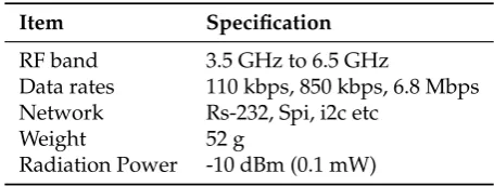
main specifications of the UWB wireless communication modules are radiation power –10 dBm and RF 76
Band 3.5 6.5 GHz as shown in Table1. The frequency bands of the UWB wireless telecommunications 77
modules are a total of six standard frequency channels as shown in Table2and support band widths 78
(a) (b)
Figure 1.This is a figure,UWB Wireless Telecommunication Module: (a) UWB Radio Repeater. (b) UWB Module.
Table 1.Main Specifics of UWB Wireless Telecommunication Module
Item Specification
RF band 3.5 GHz to 6.5 GHz
Data rates 110 kbps, 850 kbps, 6.8 Mbps Network Rs-232, Spi, i2c etc
Weight 52 g
Radiation Power -10 dBm (0.1 mW)
Table 2.Frequency bands (MHz) of the UWB wireless modules by channel
Channel Centre Frequency Band
1 3494.4 3244.8 - 3744.0
2 3993.6 3774.0 - 4243.2
3 4492.8 4243.2 – 4742.4
4 3993.6 3328.0 – 4659.2
5 6489.6 6240.0 – 6739.2
7 6489.6 5980.3 – 6998.9
2.2. Experimental conditions and experimental method 80
The developed wired / wireless base station module and UWB wireless telecommunication 81
module are used to secure the communication lines between the rescue workers and the command post 82
and to locate the fire workers in cases where the existing communication base has become inoperable 83
when an indoor fire has occurs and whether the communication signal activation is valid or not 84
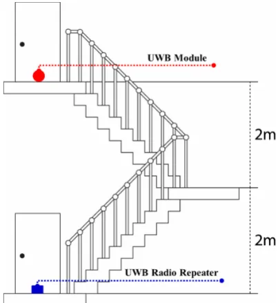
should be judged. Figure2shows experiments for signal positioning measurement for the UWB 85
wireless module. The outdoor open space is used as a test site for comparison and Figure2shows the 86
program and operation screen for the evaluation of the positioning performance for a total of six indoor 87
environments such as the passage, closed indoor space where obstacles exist, stairs, states where fire 88
door and glass have been closed. The details of the structural spaces for individual experimental 89
environments are as shown in Table3. Figure3is a side view for positioning in vertical stairs. A UWB 90
radio repeater was installed on the stair landing and UWB modules were installed on individual floors 91
for measurement. For the positioning of the UWB wireless modules, signals were measured at every 92
floor in the case of horizontal spaces and were installed on stair landings in the case of environments 94
where corridors, which are horizontal-vertical spaces as with stairs, are connected to stairs, to measure 95
communication signals with telecommunication modules. In general buildings, the partitions between 96
corridors and indoor spaces are fire walls or simple walls, and the doors are usually glass doors and fire 97
doors. Therefore, to test the mutual communication between the corridors and the partitioned spaces, 98
the glass door and the fire door were closed before the communication positioning experiment was 99
conducted. The frequencies used for UWB signal positioning in the six types of spatial environments 100
are UWB standard frequency 6 channels (1ch, 2ch 3ch, 4ch, 5ch, 7ch) as shown in Table2and the band 101
ranges by frequency were also specified. Therefore, the performance was examined by evaluating the 102
difference between the distance information calculated between modules by frequency as shown in 103
Table2and actual distance information and the distance measurement success rates. 104
Figure 2.Setup for UWB telecommunication module and evaluation for performance evaluation
The performance of the UWB wireless module was evaluated by calculating the distance 105
information by calculating the time for the wireless telecommunications module to receive the 106
data packets transmitted from the wired / wireless base station module as the time of flight (ToF). 107
In addition, 130-byte data packets were transmitted for distance measurement, and the distance 108
measurement success rate was calculated by counting cases where all data were successfully received 109
without radio wave reflection or errors occurring in data transmission/receiving. The numbers of 110
time of attempts to transmit signals closer to 0 were judged as indicating better communication 111
environments and performance. 112
Table 3.Test Environment in Each 6 sectors for UWB RF Module
Sector
Space
Obstacle
Width(m) Length(m) Height(m)
Open space - - - None
Pathway 2.5 32.0 2.4 None
Indoor room 6.2 12.5 2.4 Arranged normal OA furniture with 1.5 m height
Stairs room 2.4 5.0 20.0 Concrete stairs
Glass door 1.8 - 2.1 between pathway and office room
Fire door(steel) 1.8 * 2.1 between pathway and office room
3. Results and discussion 113
3.1. Open space 114
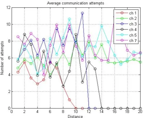
The positioning measurement in a horizontal open space where no obstacle is present was 115
experimented in an open space with no obstacles to test the distance measurement performance. Since 116
this experiment is conducted in a space with no obstruction, it becomes the reference experiment to 117
test distance measurement and communication performance later. The distance measurement showed 118
the accuracy in cm units. When positioning measurement was conducted in an open space with no 119
obstacles, as shown in Figure4, channels 2, 5, and 7 could measure distances 20 m and when they 120
could measure distances, they succeed in measuring the distances by attempting 6 10 times. The 121
communication and distance measurement performance was judged later based on the number of 122
times of attempts at this time. 123
7
3.2. Corridor 124
When positioning was measured in a spatial environment with no obstacles in a corridor in a 125
closed space, as shown in Figure5, channels 2, 5, and 7 could measure distances up to 20 m while 126
channels 1 and 3 could measure distances, which are around 5 m longer compared to open spaces 127
and channel 4 shoed a performance similar to that in the open space. In addition, since the numbers 128
of times of attempts for measurement of channels 2, 5, and 7, which could measure up to 20 m, are 129
distributed in a range of 10 to 15, it could be seen that the signal performance in the communication 130
environment was relatively lower than that in the open space. 131
7
Figure 5.Result of ToF Measurement for UWB at Corridor Sector in Enclosed Indoor
3.3. Office 132
When positioning was measured in an indoor office environment where various furniture and 133
fixtures existed in a closed space, as shown in Figure6, channels 5 and 7 showed similar measurement 134
performance as that in open spaces while channels 1, 2 and 3 showed generally lower measurement 135
performance. 136
7
However, channel 4 showed improved measurement performance on the contrary. Channel 4 137
had a band width of about 1 GHz and showed higher distance measurement communication success 138
rates by avoiding obstacles when the band width was large. In addition, we found that the number of 139
attempts increased instantaneously when the measurable distance decreased. This was identified to be 140
attributable to the fact that more errors occurred when distance measurement became impossible. 141
3.4. Vertical stairs 142
Positioning was measured in a vertical stairs space which is used as evacuation stairs in the 143
closed space. As shown in Figure3, the height between stair landings for going down one floor made 144
by simulating the experiment environment was 2 m and UWB modules were installed on the stairs 145
landings for measurement. In the results of the positioning measurement, only the channel 7 measured 146
the largest vertical height downward reaching 4.5 m as shown in Table4, and other channels could 147
measure up to a height of 4m. 148
Table 4.Distance and Number for UWB Contacting between UWB Radio Repeater and Module
(a) Distance of TOF Measurement
Test No. 1ch 2ch 3ch 4ch 5ch 7ch
1 205 193 164 197 165 203
2 482 468 429 450 431 433
3 0 0 0 0 0 448
4 0 0 0 0 0 0
(b) Trying Number for Contacting between UWB Radio Repeater and Module
Test No. 1ch 2ch 3ch 4ch 5ch 7ch
2 6.4 11.2 5.2 7.1 10.9 7.1
4 4.2 9.7 37.4 5.6 12.6 9.0
6 0 0 0 0 0 8.7
8 0 0 0 0 0 0
3.5. Glass door and fire door 149
Positioning was measured in environments where office spaces separated by corridors and 150
reinforced concrete wall structures, glass doors, or fire doors were installed in closed spaces. When 151
the experiments were conducted in spaces divided by 8 mm thick tempered glass doors and 1.5 mm 152
steel plate class A fire doors, respectively, as shown in Figure7and Figure8, channels 1 to 5 could not 153
measure distances exceeding 5 m at the maximum in both the glass door and fire door environments 154
while channel 7 could measure distances up to 17 m in the glass door environment and up to 10 m 155
in the fire door environment. However, the differences between the actual distance information and 156
the measured distances were at least 2 m. This can be considered attributable to the fact that the glass 157
door and the fire wall acted as obstacles leading to the multipath phenomenon of UWB radio waves so 158
that the radio waves were transmitted/received after going around longer distances than the actual 159
7
Figure 7.Result of ToF Measurement for UWB at Office and Pathway Sector with Closed Glass Door
7
Figure 8.Result of ToF Measurement for UWB at Office and Pathway Sector with Closed Fire Door
In the results of experiments in the above six environments, as shown in Figure 9, the 161
communication performance and distance measurement performance of channel 7 with frequency 162
6489.6 MHz and band width 1081.6 MHz were shown to be the best in general, and it was identified 163
that the number of attempts for communication increased when obstacles existed in the same closed 164
space leading to poorer communication performance and shorter measurable distances. Also, it could 165
be seen that the communication reachable distance was remarkably shorter in emergency stairs, which 166
is one of the main evacuation routes, compared to other environments. In this study, the wired / 167
wireless base station modules were arranged at a intervals of about 20 meters for measurement of 168
communication with the wireless telecommunication module and distances and the errors between 169
actual distances and the distances information obtained using ToF were found to be about 50 cm. It is 170
considered that the distance errors can be reduced by accumulating indoor environment measurement 171
Figure 9.Result of Telecommunication Distance for UWB in each 6 Sectors
4. Conclusion 173
When a fire or disaster has occurred, casualties can be minimized only in cases where firefighters 174
and rescue and emergency workers immediately respond and conduct activities. However, in 175
cases where the communication infrastructures have been destroyed, communication connections 176
using TRS (Trunked Radio System, frequency common communication) and LTE (Long Term 177
Evolution) communication networks are impossible in closed spaces. The absence of rescue workers’ 178
communication connection can lead to increases in casualties due to errors and delays in responding 179
activities and can bring about risks to rescue workers’ safety. Through this study, the following 180
conclusions on UWB communication module performance evaluation were drawn. 181
• A performance evaluation method was presented for the UWB communication module developed 182
to construct closed indoor communication environments using UWB wireless telecommunication 183
networks, which transmit massive digital data with low power in short distance sections. 184
• Experiments in 6 spatial environments showed that the communication performance and distance 185
measurement performance of channel 7 with frequency 6489.6 MHz and bandwidth 1081.6 MHz 186
are the best. 187
• It was shown that the installation spaces for the UWB communication module could be 20 m 188
as communication and distance measurement are possible in 20 m and that communication 189
environments can be constructed in closed spaces in cases where multi-channels are used. 190
• In particular, the communication distance at stairs was measured to be about 5 m indicating 191
that the communication module should be installed at intervals of two story building height for 192
smooth communication at vertical stairs. 193
Hereafter, we will conduct experiments in the heat and smoke situations in the indoor fire situation 194
to investigate the possibility of using the UWB communication network. 195
References 196
1. Ministry of Public Safety and Security,Verification of Test-bed Result for Disaster Telecommunication Network 197
Construction, Policy Resource of Ministry of Public Safety and Security, 2014, 13 .
198
2. Kim, Y.D.; Kim, Y.G.; Lee, S.H.; Kang, J.H.; An, J. Portable Fire Evacuation Guide Robot System.Robots and 199
Systems, 2009. IROS 2009. IEEE/RSJ International Conference on. IEEE,2009. 2789-2794.
200
3. Kim, Y.D.; Kang, J.H.; Sun, D.H.; Moon, J.I.; Ryuh, Y.S.; An, J. Design and Implementation of User-Friendly
201
Remote Controllers for Rescue Robots Used at Fire Sites.Proceedings of IEEE/RSJ IROS,2010, 377-382.
202
4. Kim, Y.D.; Kwon, S.; Kim, H.J.; Park, J.W. A Fundamental Study on Wi-Fi Based Communication Methods for
203
Enclosed Spaces.Journal of Korean Society of Hazard Mitigation,2015,15(6), 237-242.
204
5. Song, K.H. Transmission and Reflection Characteristics Measurements at the 60GHz for the Various
205
Obstacles.Journal of the Korea Institute of Information and Communication Engineering,2008,12(1), 25-32.
6. Jung, M.S.; Bae, S.H.; Lee, B.S. Analysis of Building Material Reflection and Transmission Characterization for
207
ISM band.Proceedings of KICS,2002, 212-215.
208
7. Oh, S.B.; Kim, S.K.; Jee, S.W.; Lee, C.H.; Kim, H.G.; Sakong, S.H. A Study on the Response Characteristics of
209
Fire Frequency 447 MHz and 2.4 GHz.Proceedings of KIFSE,2011, 31-34.
210
8. Nagatani, K.; Kiribayashi, S.; Okada, Y.; Otake, K.; Yoshida, K.; Tadokoro, S.; Nishimura, T.; Yoshida, T.;
211
Koyanagi, E.; Fukushima, m.; Kawatsuma, S. Emergency response to the nuclear accident at the Fukushima
212
Daiichi Nuclear Power Plants using mobile rescue robots.Journal of Field Robotics,201330(1), 44-63.
213
9. Wylie-Green, M. P.; Ranta, P. A.; Salokannel, J. Multi-band OFDM UWB solution for IEEE 802.15. 3a WPANs.
214
InAdvances in Wired and Wireless Communication, 2005 IEEE/Sarnoff Symposium onIEEE,2005, 102-105.
215
10. Gigl, T.; Janssen, G. J.; Dizdarevic, V.; Witrisal, K.; Irahhauten, Z. Analysis of a UWB indoor positioning
216
system based on received signal strength. InPositioning, Navigation and Communication, 2007. WPNC’07. 4th 217
Workshop on. IEEE,2007, 97-101.
218
11. Chen, G.; Zhang, Y.; Xiao, L.; Li, J.; Zhou, L.; Zhou, S. Measurement-based RSS-multipath neural network
219
indoor positioning technique. InElectrical and Computer Engineering (CCECE), 2014 IEEE 27th Canadian 220
Conference on.IEEE,2014. 1-7.
221
12. IEEE Std 802.12.4a-2006, Amendment to 802.15.4-2006: Wireless Medium Access Control (MAC) and Pysical
222