Plasma and Fusion Research: Regular Articles Volume 9, 1401092 (2014)
Influence of a Guide Field on Collisionless Driven Reconnection
∗)Ritoku HORIUCHI
1,2), Shunsuke USAMI
1)and Hiroaki OHTANI
1,2)1)National Institute for Fusion Science, Toki 509-5292, Japan 2)The Graduate University for Advanced Studies, Toki 509-5292, Japan
(Received 24 January 2014/Accepted 19 April 2014)
The influence of a guide field on collisionless driven reconnection is investigated by means of two-dimensional electromagnetic particle simulation in an open system. In a quasi-steady state when reconnection electric field evolves fully, a current layer evolves locally in a narrow kinetic region and its scale decreases in proportion to an electron meandering scale as the guide field is intensified. Here, the meandering scale stands for an average spatial scale of nongyrotropic motions in the vicinity of the reconnection point. Force terms associated with off-diagonal components of electron and ion pressure tensors, which are originating from nongyrotropic mo-tions of charged particles, becomes dominant at the reconnection point and sustain the reconnection electric field even when the guide field is strong. It is also found that thermalization of both ions and electrons is suppressed by the guide field. For the weak guide field, an electron nonthermal component is significantly created through a fast outburst from the kinetic region, while for the strong guide field, an ion nonthermal component is generated through the acceleration by an in-plane electric field near the magnetic separatrix.
c
2014 The Japan Society of Plasma Science and Nuclear Fusion Research
Keywords: guide field, collisionless driven reconnection, meandering effect, energy conversion process DOI: 10.1585/pfr.9.1401092
1. Introduction
It is widely believed that magnetic reconnection ob-served in various natural systems is controlled by com-mon or similar physical processes, regardless of large dif-ferences in magnetic configurations and spatial-temporal scales [1]. A series of particle-in-cell (PIC) simulation studies has disclosed that that there are two microscopic mechanisms, which break a frozen-in condition and ex-cite magnetic reconnection in a collisionless plasma with-out any guide field: one is due to anomalous resistivity associated with plasma instabilities [2–8] and the other is due to the effect of a nongyrotropic particle motion, called “meandering motion”, in the vicinity of a reconnection point [9–13].
Because the amplitude of the meandering motion de-creases with the guide field [14], it is expected that mag-netic reconnection in a system with a strong guide field, such as fusion devices, may be altered from that in natural systems with no or a small guide field, such as solar corona and the earth’s magnetosphere. To clarify the influence of the guide field on collisionless driven reconnection, Ho-riuchi and Sato [14] first applied a two-dimensional PIC simulation to a microscopic open system with the guide field, that was subject to an external driving flow. They found that under the influence of an external driving flow, an electron current layer thicness decreases with the guide field, and the reconnection rate is determined by the
driv-author’s e-mail: [email protected]
∗)This article is based on the invited talk at the 30th JSPF Annual Meeting (2013, Tokyo).
ing electric field. A series of numerical studies has ex-tensively investigated the effect of a guide field on spon-taneous reconnection [15–17]. The force term associated with the electron nongyrotropic pressure was found to play an important role in breaking electron frozen-in condition, even with a strong guide field.
Based on results from two-dimensional PIC simula-tions for an open system with an external driving source, the influences of a strong guide field on particle kinetic effects and energy conversion processes in collisionless driven reconnection are discussed in Sec. 2 and Sec. 3, re-spectively. Summary and discussion are given in Sec. 4.
2. Influence of a Guide Field on
Parti-cle Kinetic E
ff
ects
To clarify the influence of a guide field on collision-less driven reconnection, we have carried out a series of two-dimensional particle simulation runs in a micro-scopic open system, using “PASMO” code [9, 11, 12, 18]. The initial conditions used for these simulations were one-dimensional equilibrium with an antiparallel magnetic field along thex-axis and a uniform guide field along the z-axis,
Bx(y) = B0tanh(y/L), (1)
Bz(y) = Bz0, (2) P(y) = P0+B
2 0
8πsech2(y/L), (3)
whereB0,Bz0andP0are constants andLis the scale height along they-axis. The initial particle distribution was
as-c
2014 The Japan Society of Plasma
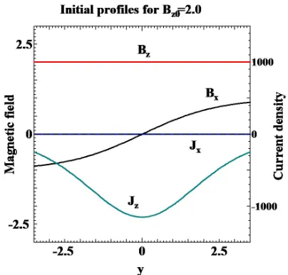
Fig. 1 Spatial profiles of magnetic field and current density in the initial state forBz0/B0 =2.0, where the spatial scale is normalized byc/ωce.
sumed to be a shifted Maxwellian with spatially constant temperature and average particle velocity equal to the dia-magnetic drift velocity. Figure 1 shows the spatial pro-files of the magnetic field and the current density along the y-axis in the initial condition for the case Bz0 = 2.0B0. An open boundary condition was adopted in the PASMO code. That is, an external driving electric field was im-posed in the oppositez-direction at the upstream bound-ary (y = ±yb) to supply the particles into the simulation domain from the upstream boundary. The supplied parti-cles satisfied the shifted Maxwellian with average veloc-ity equal toE×Bdrift velocity. The downstream bound-ary (x=±xb) was free, across which plasma could freely flow in or out. For this, it was assumed that the particle distribution was continuous across the downstream bound-ary [11, 18]. Thus, the total number of particles in the sys-tem changed with time, but the charge neutrality condition was always satisfied.
We carried out three simulation runs with diff er-ent guide fields while keeping other simulation param-eters the same; i.e., the total number of particles was 139,673,600, the simulation domain size was 2xb×2yb= 19.15ρi0×6.38ρi0 (ρi0: initial ion Larmor radius defined usingB0), the ion-to-electron temperature ratioTi/Te=1, the ion-to-electron mass ratiomi/me = 100, the ratio of electron plasma frequency to electron gyration frequency ωpe/ωce = 6, L/ρi0 = 2.1, and the driving electric field imposed at the upstream boundaryEd = −0.04B0. Fig-ure 2 shows temporal evolutions of magnetic fluxes ac-cumulated in the upstream (solid curves) and downstream (dashed curves) regions of a reconnection point for three different guide fields where black, blue, and red curves are results forBz0/B0 = 0, 1, and 2, respectively. Magnetic flux accumulates in the upstream region in the same man-ner regardless of the guide field strength until magnetic
re-Fig. 2 Temporal evolutions of magnetic fluxes accumulated in the upstream (solid curves) and downstream (dashed curves) regions of a reconnection point for three diff er-ent guide fields,Bz0/B0=0(black), 1(blue), 2(red).
connection sets in. When the current layer is compressed as thin as ion kinetic scale, magnetic reconnection occurs and reconnected magnetic flux is carried away towards the downstream region by fast reconnection outflow [9,11,12]. As the guide field is intensified, the starting period of mag-netic reconnection is delayed, and the maximum value of magnetic flux accumulated in the upstream increases. This suggests that the particle kinetic effect leading to excitation of magnetic reconnection strongly depends on the guide field and that the kinetic scale decreases as the guide field increases.
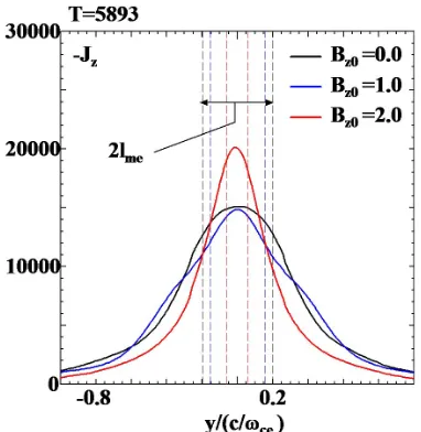
Figure 3 shows the current density profiles along the y-axis atωpet=5893 forBz0/B0=0 (black), 1 (blue), and 2 (red). For comparison, the average amplitude of electron meandering motions,lme, for each case is shown by a ver-tical dashed line, which is given by the distance from the reconnection point that satisfies
ρe(xrec, y)=y. (4)
Herexrecis thex-coordinate of the reconnection point, and ρe(xrec, y) is the local electron Larmor radius defined using the total magnetic fieldB=(B2
Plasma and Fusion Research: Regular Articles Volume 9, 1401092 (2014)
Fig. 3 Spatial profiles of the z-component of current density along they-axis atωpet = 5893 for Bz0/B0 = 0 (black curve), 1 (blue curve), and 2 (red curve). Vertical dashed lines indicate sizes of electron meandering orbits for each case.
Fig. 4 Spatial profiles of the electron number density (solid) and thez-component of electron flow velocity (dashed) along they-axis for the same conditions as in Fig. 3.
is mainly carried by electrons, and it is given by the prod-uct of number density and flow velocity. Figure 4 shows the spatial profiles of the electron number density (solid) and the z-component of electron flow velocity (dashed) along they-axis for the same conditions as in Fig. 3. The depressed density profile appears in the central region of the current sheet due to complex meandering motions and convergent plasma inflows [11, 19], while the flow velocity profiles have similar structures with only one peak for each case. Especially, a clear shoulder structure is formed on the density profile forBz0/B0=1 (solid blue curve). Thus,
the shoulder-like structure in the current density profile in Fig. 3 corresponds to that in the density profile in Fig. 4.
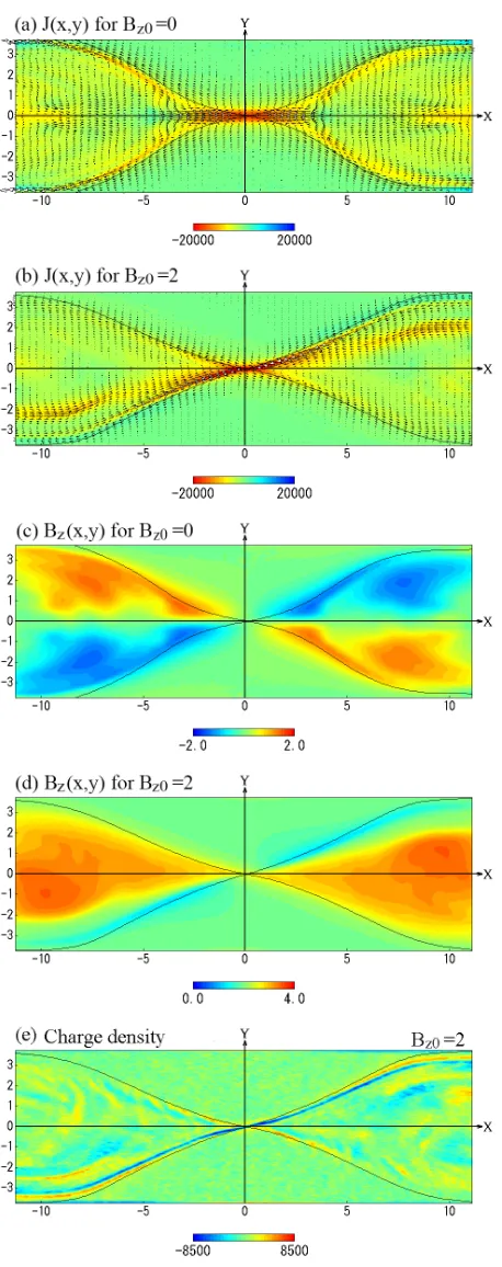
Figure 5 illustrates the spatial profiles of the current density, the z-component of the magnetic field, and the charge density in thexy-plane atωpet=5893 forBz0/B0= 0 andBz0/B0 =2. For the strong guide field case the out-of-plane or thez-component of the magnetic field evolves dynamically into a complex form, which is controlled by the initial uniform guide fieldBz0, the quadrupole field cre-ated by the Hall current, and compression by the external driving flow, as shown in Figs. 3 and 5. The current layer grows in a long and narrow region near the magnetic sep-aratrix, and its shape becomes asymmetric against the ver-tical axis passing through a reconnection point, in contrast to that for a case with no guide field (Figs. (a) and 5-(b)) [14]. Because the out-of-plane magnetic field in the strong guide field case consists of a symmetric guide field and quadrupole field created by the Hall current, the mag-netic pressure decreases in the region where the sign of the quadrupole field is opposite to that of the guide field, while in the other region, the magnetic pressure increases. The external driving plasma flow strongly compresses the weak magnetic pressure region, and thus the asymmetric profile of the out-of-plane magnetic field is formed (Fig. 5-(d)). Strong compression creates an electron-rich region in the region of the weak magnetic field near the separatrix, where the electron current layer evolves (Figs. 5-(b) and 5-(e)).
Previous simulations with no guide field [10, 13, 19, 20] have disclosed that the effect of the meandering mo-tion in the vicinity of a reconnecmo-tion point plays a dom-inant role in breaking the plasma frozen-in condition and exciting collisionless reconnection. Let us consider how the microscopic mechanism responsible for collisionless reconnection is altered in the presence of the guide field. Here, it is useful to examine the non-ideal terms in the two-fluid equations,
E+uj×B =
mj qj
(∂
∂t+uj· ∇)uj
+ 1
njqj (∂P¯j
∂x +
∂pj
∂x), (5)
where the subscript j(=i,e) denotes ion or electron, and ¯
Fig. 5 Spatial profiles of (a) and (b) the current density, (c) and (d) thez-component of magnetic field, and (e) the charge density in the xy-plane atωpet =5893 for Bz0/B0 =0 in Panels (a) and (c) andBz0/B0 =2 in Panels (b), (d), and (e). In the top two panels, color contours and vector plots stand for the z-component and xy-components of current density, respectively. The black curve represents the magnetic separatrix.
Fig. 6 Spatial profiles of thez-components of ideal and non-ideal terms in Eq. (5) at ωpet = 5893 for the case of
Bz0 = 2.0B0. Top and bottom panels show the profiles for electrons and ions along they-axis, respectively.
the strong guide field [14–16]. Since the off-diagonal com-ponents of pressure tensor terms originate from the me-andering motion in the vicinity of a reconnection point, we conclude that the particle kinetic effect due to the me-andering motion plays a key role in breaking the plasma frozen-in condition even when a strong guide field exists.
3. Influence of a Guide Field on
En-ergy Conversion Processes
Plasma and Fusion Research: Regular Articles Volume 9, 1401092 (2014) frozen-in condition and exciting collisionless
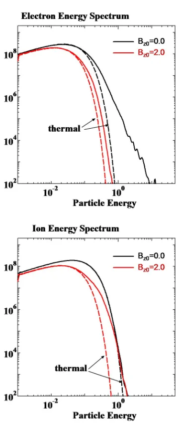
reconnec-tion. Through collisionless reconnection, fast energy con-version from magnetic field to particles also occurs as well as global change in magnetic field topology. In this sec-tion, we examine how the guide field affects the energy conversion process. Figure 7 shows the electron (top) and ion (bottom) energy spectra Fi/e() at ωpet = 5893 for Bz0/B0 =0 (black), and 2(red), whereis the particle en-ergy, and the energy spectrumFi/e() is defined by
Fi/e()d=total number of ions/electrons. (6) For comparison, the thermal component of each spectrum, Ft(), is also plotted by dashed curves in Fig. 7. Here, the thermal component is given by a fitted curve for the ther-mal distribution as
Ft()=α √
exp(−β), (7)
Fig. 7 Electron (top) and ion (bottom) energy spectra atωpet=
5893 forBz0/B0 =0 (black), and 2(red). Dashed curves are the thermal component of each spectrum.
whereαandβare fitting parameters and the fit was carried out using only the data in the energy region lower than that at the peak position of each spectrum.
Dissipation of magnetic field energy occurs inside a narrow electron kinetic region in the vicinity of the re-connection point. The thickness of the dissipation region scales as the meandering orbit amplitude, as discussed in Sec. 2. Therefore, as shown in Fig. 7, thermalization of both ions and electrons is suppressed to a lower level as the guide field is intensified. In contrast, the electron non-thermal component is observed significantly for the case of no guide field. To understand this phenomenon, we plot the electron distribution functionFe for Bz0/B0 = 0 (top) andBz0/B0=2 (bottom) in the phase space (vx, vy) in Fig. 8, where electrons were sampled in the downstream region of the reconnection point within the size of area
Δx×Δy = 4.99ρe0 ×3.33ρe0 (ρe0: initial electron Lar-mor radius evaluated using B0). As discussed in Sec. 2, unmagnetized meandering particle predominantly exists in the vicinity of the reconnection point. As the guide field intensifies, particles become magnetized and number of ummagnetized particles decreases. Unmagnetized parti-cles are directly accelerated by the Hall electric field and the reconnection electric field. They not only form a fully developed current layer in the kinetic region but also pro-vide a channel for fast electron outburst flowing towards the downstream. It is obviously seen in Fig. 8 that there exists a large deviation from the thermal distribution for Bz0/B0 = 0, while the distribution changes to a compact structure consisting mainly of the thermal component for Bz0/B0 =2. This is the reason why the electron nonther-mal component is observed significantly when no guide field is present. In contrast, for the strong guide field, the nonthermal component appears in the ion distribution. We will discuss the reason for this below.
Fig. 8 Electron distribution functions at ωpet = 5893 for
Bz0/B0 = 0 (top) and Bz0/B0 = 2 (bottom) in phase space (vx, vy), where electrons were sampled around a
point (x, y)=(3.89ρi0,0) in the downstream region. Elec-tron velocity in the figure is normalized by the velocity of light.
(a black dashed curve in Fig. 9). The accelerated elec-trons move away from the reconnection region along the inclined current sheet (see Fig. 5-(b)). Note in Fig. 9 that for a strong guide field, ions, unlike electrons, obtain the kinetic energy mainly in the downstream region [21]. Let us consider how ions obtain kinetic energy there. Figure 10 shows the spatial profiles of the function|E+ui×B|, the y-component of the electric fieldEyand the in-plane compo-nent of the ion flow velocity in thexy-plane atωpet=5893 for Bz0/B0 = 2. The ion frozen-in condition is strongly violated near the magnetic separatirix mainly due to the in-plane component of the electric field (|E+ui×B|0). Most of ions are supplied across the separatrix from the up-stream to the downup-stream. When ions move across the
sep-Fig. 9 Spatial profiles of electron and ion energies at ωpet =
5893 for Bz0/B0 =0 (blue and green) and Bz0/B0 = 2 (black and red) where the solid and dashed curves rep-resent the profiles of total and kinetic energies per parti-cle, respectively. The profiles in the upstream (negative y) and in the downstream (positivex) are combined at a reconnection point ((x, y)=(0,0)).
Fig. 10 Spatial profiles of (top) the function|E+ui ×B|and (bottom) they-component of electric fieldEy and the in-plane component of ion flow velocity in thexy-plane atωpet=5893 forBz0/B0=2, where color contours and vector plots in the bottom panel stand for electric field
Plasma and Fusion Research: Regular Articles Volume 9, 1401092 (2014) aratrix, they are accelerated directly by the in-plane
elec-tric field towards the downstream region (bottom panel). Because the out-of-plane component of magnetic field is strongly amplified in the downstream region for a driven case (Fig. 5-(d)), ions are magnetized as soon as they move into the downstream (top panel). Thus, magnetized ions move towards the downstream boundary with fast outflow velocities. This ion outflow corresponds to the nonthermal component of the ion energy spectrum shown in Fig. 7. We conclude that for the weak guide field, a nonthermal component of electrons is significantly created through the fast electron outburst from the kinetic region, while for the strong guide field, a nonthermal component of ions is generated through the acceleration by the in-plane electric field near the magnetic separatrix.
4. Summary
We have investigated an influence of a guide field on collisionless driven reconnection by means of two-dimensional electromagnetic particle simulation in an open system. The reconnection current density evolves locally in the narrow electron kinetic region in which unmagne-tized electrons exist, and the dissipation of magnetic en-ergy predominantly occurs there. As the guide field is in-tensified, both the thickness of the current layer and the number of the unmagnetized electrons decrease in propor-tion to the electron meandering scale. The force terms as-sociated with the off-diagonal components of electron and ion pressure tensors, which is originating from a nongy-rotropic motion of charged particles, becomes dominant at the reconnection point and sustain reconnection electric field even when a strong guide field is present. We also found that in the presence of the guide field, thermalization of both ions and electrons is suppressed to a lower level because the dissipation region shrinks as the guide field is amplified. For a weak guide field, a nonthermal com-ponent of electrons is significantly created through a fast outburst from the kinetic region, while for a strong guide field, a nonthermal component of ions appears through the acceleration by an in-plane electric field near the magnetic separatrix.
As discussed in Sec. 1, there are two microscopic trig-gering mechanisms for collisionless reconnection. In this paper, we have focused on the influence of the guide field on the particle kinetic effect, based on the two-dimensional PIC simulation results. For complete understanding of col-lisionless reconnection, another important subject to be in-vestigated is the role of anomalous resistivity associated with plasma instabilities in the presence of a strong guide field. Previous numerical simulation studies in the case of no guide field [4, 7, 8, 20] have demonstrated that anoma-lous resistivity is generated through the excitation of a drift kink instability [3] in the ion-scale current sheet after
non-linear modification of the current sheet by a lower hybrid drift instability [2]. However, it is easily expected that the anomalous resistivity associated with plasma instabilities is largely altered by a strong guide field. Because these plasma instabilities have a wavevector normal to the two-dimensional reconnection plane, three-two-dimensional analy-ses are needed to reach the complete understanding of col-lisionless driven reconnection in the presence of a strong guide field. This problem will be addressed in the near future.
Acknowledgments
The simulation was performed by employing the Plasma Simulator at the National Institute for Fusion Sci-ence. This study was partially supported by a Grant-in-Aid for Scientific Research from the Japan Society for the Pro-motion of Science (Grant No. 23340182), the Research Cooperation Program on “Hierarchy and Holism in Natu-ral Sciences” at the National Institutes of NatuNatu-ral Sciences, and General Coordinated Research at the National Institute for Fusion Science (NIFS12KNSS028).
[1] M. Yamada, Rev. Mod. Phys.82, 603 (2010).
[2] N.A. Krall and P.C. Liewer, Phys. Rev.4, 2094 (1971). [3] Z. Zhu and R.M. Winglee, J. Geophys. Res.101, 4885
(1996).
[4] R. Horiuchi and T. Sato, Phys. Plasmas6, 4565 (1999). [5] W. Daughton, Phys. Plasmas6, 1329 (1999).
[6] W. Daughton, G. Lapenta and P. Ricci, Phys. Rev. Lett.93, 105004 (2004).
[7] T. Moritaka, R. Horiuchi and H. Ohtani, Phys. Plasmas14, 102109 (2007).
[8] T. Moritaka and R. Horiuchi, Phys. Plasmas 15, 092114 (2008).
[9] R. Horiuchi and T. Sato, Phys. Plasmas1, 3587 (1994). [10] M. Hesse, K. Schindler, J. Birn and M. Kuznetsova, Phys.
Plasmas6, 1781 (1999).
[11] W. Pei, R. Horiuchi and T. Sato, Phys. Plasmas 8, 3251 (2001).
[12] W. Pei, R. Horiuchi and T. Sato, Phys. Rev. Lett. 87, 235003 (2001).
[13] R. Horiuchi and H. Ohtani, Comm. Comp. Phys.4, 496 (2008).
[14] R. Horiuchi and T. Sato, Phys. Plasmas4, 277 (1997). [15] M. Hesse, M. Kuznetsova, K. Schindler and J. Birn, Phys.
Plasmas12, 100704 (2005).
[16] M. Hesse, Phys. Plasmas13, 122107 (2006). [17] P. Pritchett, Phys. Plasmas12, 062301 (2005).
[18] H. Ohtani and R. Horiuchi, Plasma Fusion Res. 4, 024 (2009).
[19] A. Ishizawa and R. Horiuchi, Phys. Rev. Lett.95, 045003 (2005).
[20] R. Horiuchi, S. Usami, H. Ohtani and T. Moritaka, Plasma Fusion Res.5, S2006 (2010).