Abstract—This paper presents research in steering control techniques for an automated all-terrain vehicle (ATV). According to steering wheel angle and Gas or Break Pedal, the proposed fuzzy inference logic can provide needed assist to the left and right motor position which controls the position of build-in proportional valve. Position valve increase or decrease the fluid velocity which increase or decrease the hydraulic motor speed and vehicle speed .different speed for left and right motor cause turn left or right. Under experts’ knowledge of fuzzy control, the electro-Hydraulic power steering system can satisfy smooth turning left or right. Modeling and Experimental results demonstrate that the proposed method is reasonable and feasible.
Index Terms—Fuzzy logic, all terrain vehicles, PID Control.
I. INTRODUCTION
The University of Siegen in Germany working in the research and development of an autonomous ATV (DORIS) project as in Fig. 1. As it is still a work-in-progress, a problem has been identified in the designing and implements a steering control system.
Fig. 1. DORIS robot.
Controller design for any system needs some knowledge about the system. Usually this involves a mathematical description of the relation among inputs to the process, its state variables, and its Output. This description is called the model of the system. The model can be represented as a set of transfer functions for linear time invariant systems or other relationships for non-linear or time variant systems. Modeling of complex systems may be very difficult task.
In a complex system such as a multiple input and multiple outputs system inaccurate models can lead to unstable systems, or unsuitable system performance. Fuzzy Logic
Control (FLC) is an effective alternative approach for systems which are difficult to model. The FLC uses the qualitative aspects of the human decision process to construct the control algorithm. This can lead to a robust controller design [1].
The aim of this research is to develop steering control system by using fuzzy logic Controller with PID Controller.PID position control system to control the forward and backward Vehicle movement designed and discussed in previous paper [2], [3]. To turn the Vehicle left and right one side should have different speed than the other side and for full turning one wheel should be completely stop and the other should be at maximum speed.
II. SYSTEM DESCRIPTION
DORIS robot (dual media Outdoor Robot Intelligent System) as shown in Fig. 1, is a research project of the Institute for Real-Time Learning Systems in Siegen University. It is an autonomous acting vehicle for outdoor use under the most difficult conditions. It consists of many subsystems like gas control system, break control system, steering control system, security system.
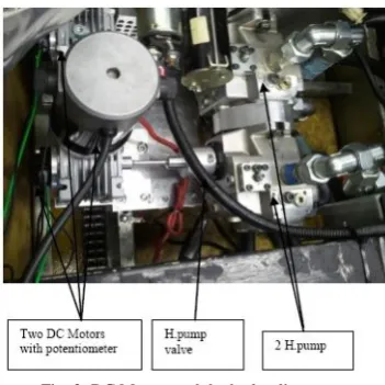
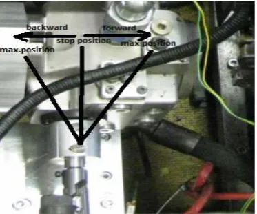
Tow variable hydraulic pumps one for left and one for right side controlled by two 12V DC motor as shown in Fig. 2 by rotating the pump valve clockwise allows to drive the wheel forward and rotating the pump valve counterclockwise allows to drive the wheel backward. Two potentiometers connected to the two motors to detect the angular position and send the signal to the atmeaga16 microcontroller to process it and correct the error.
Fig. 2. DC Motors and the hydraulic pumps.
Tow Pedal one for driving the Vehicle forward and the other to drive the vehicle backward as it shown in Fig. 3 the task is to rotate each DC Motor independently to reach the desired position according to the driver desired signal.
Modeling, Design and Implement of Steering Fuzzy PID
Control System for DORIS Robot
Khaled Sailan, Klaus D. Kuhnert, and Hradik Karelia
Fig. 3. Gas and brake pedal.
H bridge electrical circuit with the microcontroller platform Fig. 4 shows the brain of the system where all the control operations, error correction and sensors information's processes in the ATMEGA 16 microcontroller by using AVR Studio software and c program.
Fig. 4. H bridge and microcontroller platform.
Hydrostatic transmission Fig. 5 and Fig. 6 shows the hydraulic circuit that include the variable hydraulic pump where the fluid flow rate and hydraulic motors speed can control by controlling the pump angle through the DC Motor .Three hydraulic Motors used two used for both side and one for jetski when the vehicle moves on the water.
Fig. 5. Electro-hydraulic power train system.
Fig. 6. Hydraulic circuit.
III. FUZZY LOGIC CONTROLLER DESCRIPTION Fuzzy logic control is a control algorithm based on a linguistic control strategy, which is derived from expert knowledge into an automatic control strategy. Fuzzy logic control doesn't need any difficult mathematical calculation like the others control system. While the others control system use difficult mathematical calculation to provide a model of the controlled plant, it only uses simple mathematical calculation to simulate the expert knowledge. Although it doesn't need any difficult mathematical calculation, but it can give good performance in a control system . Thus, it can be one of the best available answers today for a broad class of challenging controls problems. A fuzzy logic control usually consists of the following as in Fig. 7 [4]:
1) Fuzzification: This process converts or transforms the measured inputs called crisp values, into the fuzzy linguistic values used by the fuzzy reasoning mechanism.
2) Knowledge Base: A collection of the expert control rules (knowledge) needed to achieve the control goal. 3) Fuzzy interface engine: This process will perform fuzzy
logic operations and result the control action according to the fuzzy inputs.
4) Defuzzification unit: This process converts the result of fuzzy reasoning mechanism into the required crisp value
IV. FUZZY STEERING STRATEGY DESIGN
In this paper, the Fuzzy PID steering controller shown in Fig. 8. There are two inputs, including the Gas or Break Pedal as input 1 according to the desired driving mode either forward by using the Gas Pedal or backward by using the Break Pedal and the steering wheel angle as input 2. The Fuzzy PID steering controller can handle the two DC motors position to produce desired Hydraulic pump fluid speed through the build-in proportional valve as shown in Fig. 5 and Fig. 6. Herein, the controller is only designed to achieve the reference DC motor position. we designed three driving mode, stop mode when the pedal is in the zero position, middle speed when the pedal is in the middle position and full speed when the Pedal is in the full position this three mode repeated also for driving backward by using the Break Pedal and we divided the steering wheel to 5 positions two for right turning middle and full and two for left turning middle and full. The steering wheel angle is between 90o and − 90o, i.e., the driver does not really turn. Therefore, the stop mode is excited and the motor stay in its position according to the Pedal signal. Secondly, if the assist mode is excited, the assist motor position can be obtained through an assist fuzzy inference mechanism. Larger steering wheel angle is referred to larger Vehicle turning needed.if the steering wheel is in the zero angle the vehicle will move forward or backward if we turn the Steering wheel right to the middle and Gas or Break Pedal in the middle the right DC motor should stay in the middle and the left DC motor should move backward to the zero position according to fuzzy rule. DC Motors position is controlled by PID Controller [2] as shown in Fig. 8.
Fig. 8. Fuzzy PID controller.
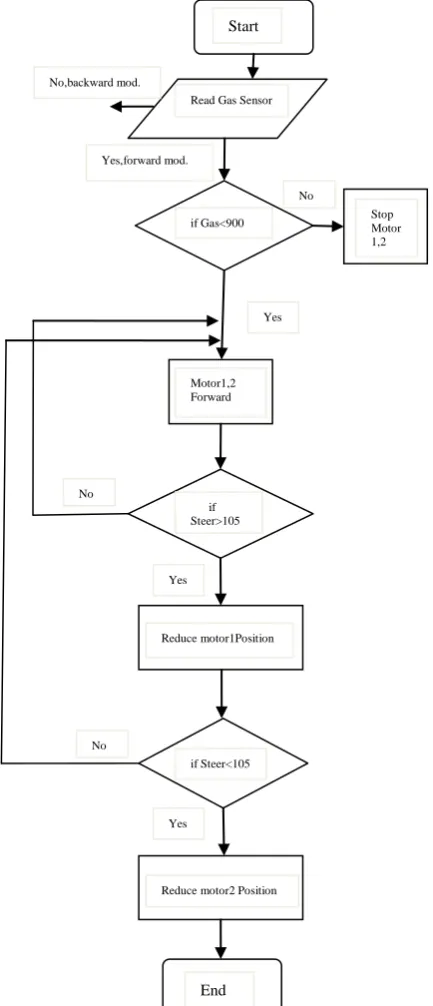
Fig. 9 shows the flow chart of the Fuzzy PID controller the sequence of the Fuzzy logic controller started by reading the signal from Gas Pedal which we set up the Gas Pedal to be for forward driving mode if there is a signal from the Gas Pedal the forward mode will start if there is a signal from the Break Pedal the backward mode will start and if there is no signal from both Pedal the two DC Motor stopped. By adding the Steer signal the controller check if the steer is right or left.
Fig. 9. Steering control system flow chart.
V. FUZZY LOGIC INFERENCE SYSTEM DESIGN Basically, a fuzzy logic system consists of one or more inputs and a single output. Each rule describes a connection between the input and the output. Through the fuzzy inference engine, each rule maps the input fuzzy sets to an output fuzzy set. Finally, the output fuzzy set is translated to a crisp value by the defuzzification process. Choose singleton fuzzification, center average defuzzification, and Mamdani implication in the inference engine [5]. The steering wheel angle and the Gas Pedal position are the inputs and the DC motor position is the output of the fuzzy inference mechanism, respectively. Input from Pedal can be divided to 3 level and input from steering divided to 5 levels output variables can be divided into 3 levels. input 1 defined as full , middle and zero and for output full_r, middle_r and
Start
Read Gas Sensor
Yes,forward mod.
if Gas<900 Stop Motor 1,2
Yes
Motor1,2 Forward
if Steer>105
Reduce motor1Position
if Steer<105
Reduce motor2 Position Yes
No
End
Yes No
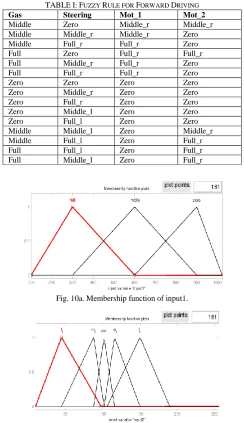
zero that make vehicle drives forwards input from steering defined as zero, full_l ,full_r ,middle_l,and middle_r. In order to improve defuzzification speed, Trimf is chosen as membership function and the weight is equal to one [6]. Figs. 10 (a, b, c) show the membership functions of input and output variables. Table I shows the assist fuzzy rule base fifteen fuzzy rules for each motor achieved the control goal represented as
TABLEI:FUZZY RULE FOR FORWARD DRIVING
Gas Steering Mot_1 Mot_2
Middle Zero Middle_r Middle_r
Middle Middle_r Middle_r Zero
Middle Full_r Full_r Zero
Full Zero Full_r Full_r
Full Middle_r Full_r Zero
Full Full_r Full_r Zero
Zero Zero Zero Zero
Zero Middle_r Zero Zero
Zero Full_r Zero Zero
Zero Middle_l Zero Zero
Zero Full_l Zero Zero
Middle Middle_l Zero Middle_r
Middle Full_l Zero Full_r
Full Full_l Zero Full_r
Full Middle_l Zero Full_r
Fig. 10a. Membership function of input1.
Fig. 10b. Membership function of input2.
Fig. 10c. Membership function of output.
Fig. 11. Response surface of motor position.
One of the testing examples is shown in Figs. 12(a), and Fig. 12(b). If we select the input 1to be in the range of full and input 2 middel right, the resulting Motor 1 position would be in the full range and Motor 2 will be in the zero position Fig. 14b show this relation [7]. Fig. 11 shows the relation between the input 1 and input 2 and the output. The inputs is the same for both motors but the output is different according the rule table and for backward the new thing in replacing the signal from Gas pedal with the signal from Break Pedal with the same value input and the output will be in the range of backward side as in Fig. 17.
For two input variables and fifteen rules, the output of the fuzzy logic system can be represented as [8]
𝐷 𝑒𝑓𝑢𝑧 = 15𝑖=1𝑃 𝑖 ∗𝑊 𝑖
𝑊 𝑖
15
𝑖=1 (1)
P[i] is the peak value of ith output membership function. W[i] is the weight associated with ith rule. The following C code fragment gives one example of how to convert fuzzy variable to crisp output.
Fig. 12a. Fuzzy rule result for Motor _1. Rules for Motor_1
Rule 1: IF (Gas is M) AND (Steering is ZE) THEN (Motor_1 is M_r)
.
Rule 15: IF (Gas is F) AND (Steering is M_L) THEN (Motor_1 is ZE
Rules for Motor_2
Rule 1: IF (Gas is M) AND (Steering is ZE) THEN (Motor_1 is M_r)
.
Rule 15: IF (Gas is F) AND (Steering is M_L) THEN (Motor_1 is F_r).
where:
Fig. 12b. Fuzzy rule result for Motor_2.
VI. EXPERIMENTS AND RESULTS
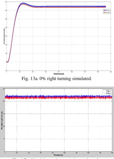
Figs. 13b, 14b band 15b shows three experimental test results for driving forward that display the two DC Motors position which control the hydraulic pump flow rate and hydraulic fluid speed the more hydraulic pump speed the more hydraulic motor speed as shown in Fig. 17. For 0% turning mode we can see that both DC Motors are almost in the same position for driving forward without turning and 30% turning mode which one DC Motor stopped in the zero position and the other Motor moved to give 30% from the turning mode .the 100% turning action done by stop one DC Motor in the zero position and the other Motor moved to the full speed position that make it turns around its self. This result can compare with the simulated result in Fig. 13a, 14a and 15a .Simulated and experimental results are nearly typical. Fig. 16 shows the state of DC Motor 1 and 2 during turning left DC Motor 2 is in a position that gives low speed and DC Motor 1 in a position that gives high speed this combination make the vehicle to rotate to the left side.
Fig. 13a. 0% right turning simulated.
Fig. 13b. 0% right turning experimental result.
Fig. 14a. 30% right turning simulated.
Fig. 14b. 30% right turning experimental result.
Fig. 15a. 100% right turning simulated.
Fig. 15b. 100% right turning experimental result.
Fig. 17. Hydraulic pump valve position.
VII. CONCLUSION
In this paper we have presented the Fuzzy PID controller for controlling the unmanned Ground vehicle steering system. The Fuzzy system designed and simulated. Real environment experiments have taken place on our vehicle. The results of these experiments are shown above and confirm that a Fuzzy PID Control System can enhance a good and smooth Vehicle turning left and right and around its self.
REFERENCES
[1] S. shukla and M. Tiwari, “Fuzzy logic of speed and steering control system for three dimensional line following of an autonomuse vehicle,” International Journal of Computer Science and Information Security, vol. 7, no. 3, March 2010.
[2] C. Alex, C. M. James, and B. A. Nabila, Autonomous All-Terrain Vehicle Steering, IEEE, 2012.
[3] K. Sailan, “DC motor angular position control using PID controller for the purpose of controlling the hydraulic pump,” in Proc. International Conference on Control, Engineering, Information Technology,vol. 1, pp. 22-26, 2013.
[4] M. Jamshidi, N. Vadiee, and T. Ross, Fuzzy Logic Control, Englewood Cliffs, N. J.: PTR Prentice Hall, 1993, pp. 89-101.
[5] S. H. Chang, “Implementation and control logic design of intelligent electric power steering system,”World Electric Vehicle Journal, 2009. [6] J. Zhang, Y. Q. Zhang, and L. P. Chen, “A fuzzy control strategy and
optimization for four wheel steering system,” IEEE, 2007.
[7] R. Kenaya and R. Chabaan, "Fuzzy controllers for electrical power steering systems," in Proc. the World Congress on Engineering and Computer Science, San Francisco, USA, October 20-22, 2010, vol. 1. [8] G. S. Nhivekar, S. S. Nirmale ,and R. R. Mudholker, "Implementation of fuzzy logic control algorithm in embedded microcomputers for dedicated application," International Journal of Engineering, Science and Technology, vol. 3, no. 4, pp. 276-283, 2011.
Sailan Khaled was born in Sanaa, Yemen, in 1978.
He received the B.S. from Sanaa University in 2001 and M.S. degree in mechatronics from Siegen University of in Germany in 2010
Since 2012, he is a PhD student in Siegen university institute of Real Time Systems
His research interests are control systems, embedded systems, robotics and autonomous systems.
Klaus-Dieter Kuhnert received his Dipl.-Ing. in
computer science from the Technical University of Aachen, Germany, in 1981, and a Ph.D. degree in computer science from the UniBw München, Germany in 1988.