* To whom all correspondence should be addressed.
The Improvement of the Digging Process
with the Sliding Surface Consideration
Kuanysh Turusbekov1, Mahabat Tusupbekov1, Nikolay Khon1,
Riza Gabdysalyk1, Serikbol Turusbekov2 and Dalel Zhailaubaev2
1D. Serikbaev East Kazakhstan State Technical University, East Kazakhstan Region, 070004 , Ust-Kamenogorsk , St. Protozanov 69, The Republic of Kazakhstan.
2Shakarim state University of Semey,
East Kazakhstan Region, 071400, Semey, St. Glinka 20À, The Republic of Kazakhstan.
DOI: http://dx.doi.org/10.13005/bbra/1983
(Received: 01 August 2015; accepted: 19 September 2015)
The article describes the energy intensity of the soil digging process and the nature of changes in the values that make up the cutting forces acting on the actuator, which are necessary for effective interaction with soil. The main goal of the research on the process of soil cutting is to find ways for the least energy-intensive and most productive separation of soil from the array. We took into account the interaction schemes of actuators with soil, as it is important both in the analysis of existing earth-moving machines operation and in the creation of new machines. We experimentally determined that a cutting angle, energy consumption, as well as a necessary vertical pressure on the cutting edge of the blade during the introduction into the soil have a significant impact on the soil digging process. We examined soil digging processes, it revealed that during the earthmoving machines operation, soil destruction occurs both due to shear strain and separation. We used the methods and equations of the theory of limiting balance that allowed deriving a series of equations to determine the resistance to soil cutting. We determined the total resistance to cutting, taking into account the resistance to chipping and crushing of soil with the cutting edge of the knife but not taking into account the resistance to the formation of the side chipping shells for flat blades. The comparison results of the calculated and experimental data on the cutting resistance of different soils, corresponding to the practical range of applied cutting angles for actuator knives of earth-moving machines, are presented.
Key words: Blade, bulldozer, cutting soil, earthmoving machines, soil.
The creation of the earthmoving machines raises the issues about the reducing of the labor and energy consumption that must be expended on the digging, i.e. the creation of such an executive device which would improve the performance of the machine, increase the efficiency of interaction with the soil and reduce the cost of
the performed work. To create such an executive device it is necessary to study the digging process. These issues are the subject of many scientific researches for both domestic and foreign scientists. A bulldozer is one of the main machines used in industrial, civil, and road construction. Its design is simple and universal, and it has a low cost of the work implementation.
efficiency is based largely on theoretical basis created by well-known scientists K.A.Artemiev, V.I.Balovnev, Yu.A.Vetrov, N.G.Dombrowskiy, A.N.Zelenin, I.A.Nedorezov, V.K.Rudnev, L.A.Khmara, R.A.Kabashev, A.S.Kadyrov, Z.A.Moldagaliev and others [1,2,3,4,5]. .Machines with the executive devices of the increased efficiency based on the use of new physical effects are considered in the works of V.I.Balovnev [6,7] and others [8,9,10,11,12,13,14,15,16,17].
The Goal: the reducing of energy consumption of the soil developing process; the expansion of the operation capabilities; the expansion of the coverage; the equipment control; the improvement of the design reliability; the increasing of the productivity; the design simplification; the expansion of the technological capabilities. The main practical goal of the studying of the digging process is to find the least energy-intensive and the most productive way of the separation soils from the solid mass.
To determine the energy consumption of the digging process, the quantities and the nature of the changes of the cutting force acting on the executive device the scheme of the interaction of the executive device with the soil must be taken into account. The schemes of interaction of the executive devices with the soil are important both for the analysis of the existing earthmoving machines and for creation of new ones.
The executive devices of the earthmoving machines in the process of the interaction with the soil experience random loads changing over the time. Depending on the type of the executive device, soil and other conditions the processes of the random loads changes are different. So the classification of both processes and the executive devices of the earthmoving machines are important.
The classification of this kind provides basic statistical characteristics and the statistical properties of the random load processes of the same type for the analysis and diagnosis of not only each executive device of the earthmoving machine, but also groups of the executive devices exposed to the load conditions of the same type.
Theoretical justification
Professor A.N.Zelenin [18] investigated the problem of the physical nature of digging, cutting forces depending on the soil conditions, the cross sectional area of the chip, the width and depth of the cut, and the cutting angle. It was found that the number of strokes of the dynamic density meter is directly proportional to the cutting force for any executive device, and it may be a criterion for the soil strength evaluation.
The reduce of the friction angle value of the soil and the blade causes the displacement of the value P?/Ps to larger cutting angles. In the research the regularities of the average power changes and the cutting energy consumption have been determined experimentally depending on the cutting depth, cutting width and cutting angle. When the cutting angle is changed from 200 to 900, the average cutting force is increasing rapidly. The coefficient is a function of the energy consumption which increases simultaneously with the increase of the cutting angle from the smallest to the greatest practical value. When ?p>800, energy consumption coefficient is close to one. It shows the factual ceasing of the cutting force oscillation. The recommended optimal cutting angle is 350-400. The decrease of the friction angle of the blade and the soil is the displacement of the value Pv/Ps to larger cutting angles.
In the research [3] it is reported that in the end of the digging process the more prism of
Fig. 2. The soil digging by blade the color layers are only in the chip.
Fig. 3.The calculation schemes for the determination of the resistance to the digging by bulldozer: a- the technique of V.I.Balovnev; b -the technique of G.N.Karasev
Fig. 4. Schemes of the forming of the drawing prism the soil before the blade will be, the lower resistance
to the cut soil promotion into this prism. The blade of the simplified profile with the cutting angle of 300 and the inclination angle of 150 is recommended. It allows to reduce the energy consumption of the digging process of the cohesive soils by 25-30%.
The experimental investigations [19] of eight blades of the different shapes of such kind
of profile with the same length have led to a number of conclusions. The variables of the profile of the blade surface significantly affect the process of the soil digging, but the soils development with broken structure (loosened) to a large extent. The optimal profile of the blade corresponds to the different values of cutting depth. The capsize angle and the inclination angle affect the process of the formation and movement of the chip on the blade surface. The curve of the blade surface, the length of the lower straight part of the blade surface, the curve change by the height and the cutting angle affect the process of digging. For the bulldozer of the general purpose in the medium soil conditions the recommended basic variables of the profile of straight blade group are the cutting angle of ?d=350, the capsize angle of 700-750, the inclination angle of 750, the installation angle of the blade visor of 900-1000, the curve radius of the blade surface at the lower straight part of the blade surface - 0,8 of its height, the upper - 1.1.
Fig. 5. The calculation scheme for determination of the resistance emerging during the forming of the drawing prism
Fig. 6. The grid lines of the sliding surfaces Fig. 7. Scheme of the cleavage shells formation with the moldboard blade in the process of the
digging consumption, the necessary vertical pressure on
the cutting edge of the blade in the process of the penetration into the soil were experimentally established. It is suggested that the change of the cutting angles in the process of digging provides more efficient operation of the blade. The inclination angle of the resultant resistance forces to the soil digging changes on the compacted soil from 150 to 210 below the horizon, on the loosened one -from 0 to 60 above and below the horizon. The distance from the cutting edge of the moldboard blade to the application point of the resultant resistance forces on the blade in the process of the compacted soil digging is equal to 0.17, and in the process of the loosened soil digging it is equal to 0.27 from the point of the blade height without a visor. The most convenient variable for the adjusting of the inclination angle of the resultant resistance to the digging is the cutting angle.
The consideration of the process of the soil digging has allowed [20] to reveal that when earthmoving machines work the soil destruction occurs both due to the shear strain and due to the separation. The type of the destruction is determined primarily by the size of the cutting angle. The transition from one type of cutting to another is characterized by a critical cutting angle. The value of the critical cutting angle decreases when the angles of the internal and external friction increase and when the kentledge increases. Its value rises when the soil cohesion and traction increase.
Using the methods and equations of the theory of limit equilibrium the author [21] derived a series of equations to determine the resistance to the soil digging. The formula (1) for the determination of the horizontal component of the digging resistance of a flat moldboard blade was proposed as a specified rate:
= (1 + ctg ∙ tg ) ℎ 2ℎ+ ctg 1 −1 + tg cos 2 2
ℎ +
+ cos2 2
2
...(1) where: ? - a length of the blade; h - a depth of the cut; ? - a bulk density of the soil with the broken structure; ? - a bulk density of the soil without the broken structure; H - a height of the drawing prism which is equal to the height of the blade; F? - the soil traction with the broken structure; K? - a factor depending on the shift angle ? and the cutting angle determined analytically.
Fig. 8. The forces acting on a soil cleavage element
Fig. 9. The scheme of distribution of forces in the elastic half-space for the development of cohesive soils by 15% and
the blades with flexible blade surface by 10% -15%. The decrease of the drawing force of the both blades will be equal to 25%.
The increase of the operation speeds changes the mode of destruction. Thus the destruction zone exceeds the zone of penetration of the executive device. The instantaneous strength of the environment increases, the relative value of the bulk soil deformation and, consequently, the destruction energy decrease. The basic principle (effect) of the dynamic (high speed) destruction of soils and rocks is that the increase of the operation speed increases the soil brittleness, the tensile strength of the environment, the destruction resistance, the decrease of the destruction energy value.
The author [22] also provides the spread velocity value of the plastic deformations (Fig. 1) as a variable characterizing the physical and mechanical properties of the soil. It is associated
with the cutting speed by the following relationship:
= sin( + )
...(2)
where ? - a velocity and the angle of the cut. Then the value of the critical velocity is expressed in terms of the rate of destruction, deformation, and cutting:
= .
...(3)
plastic deformations develop. The more contact of the surface of the moldboard blade with the soil, the more shear stress is. If the values exceed the values corresponding to the limit state, there is a shift of the sliding surface. The plastic formations reach the highest values on the destruction surface ST.
The research analysis of V.P.Stanevskiy [23] shows that despite the significant progress in the attempt to describe the effect of the speed on the process of the digging and interesting results, the author keeps to the static positions of the granular environment, and he does not take into account the emergence of the compacted core in the cut soil.
Experimental Research
The above-mentioned formulas for the determination of the resistance to the soil digging
by the executive devices of the earthmoving machines are a generalization of the experimental research aimed at the determination of the maximum value of the resistance to the digging corresponding to the end of the process when the executive devices are full of the soil. In this case, there is no possibility to estimate the process of the soil digging by energy costs to determine the effective modes of the machine operation. These formulas allow only to justify the needed drawing force and they are recommended for the design of the earthmoving machines with the executive devices of the conventional design which have experimentally determined appropriate indicators. The possibility of their application for the design of the new executive devices or for the new conditions of the application of the traditional design executive devices (e.g. underwater soil
Fig. 10. The dependence of the angle of cleavage from the cutting angle for different soils
Fig.12. Cutting resistance depending on angle of cut
extraction) is limited by the lack of experimental data.
The principle of superposition (superposition principle) is recommended for the formulas determination of the digging resistance created on the basis of the experimental research. It implies the independence of the resistance force value to the soil cutting from the presence or absence of the soil in the bowl or the drawing prism. However, experiments on the special stand the strain-measuring equipment of which allows the simultaneous measurement of the total digging force and force required only for the cutting bowl perimeter have showed that the cutting force during the digging is the value depending on the amount of the soil in the bowl as well as the availability and capacity of the drawing prism. The force value of the moldboard blade (cutting force) in the process of the digging, can reach 70% of the total resistance to the digging.
Along with the experimental research some attempts have been taken to determine the digging forces analytically. The calculations results by these formulas are significantly different from the true values, but such research is suitable for the development of the correct technique for the calculation of the resistance forces to the digging in the close connection with the research of the destruction mechanism of the soils by different mechanical ways. To create a mathematical model of the process of the soil digging by the executive devices (bulldozer blade or scraper bowl) and to establish the calculation formulas for the determination of the total resistance the researchers
have taken the photographs of these processes with the use of the colored soil layers. For this purpose the soil of the definite color was spread on the surface of the developed soil. The typical photographs of the process of the soil digging by bulldozer blade are shown in Fig. 2. The process was implemented by the use of such technique.
As a result researchers have developed and offered the calculation schemes to determine the resistance to the digging by the bulldozer blade. Versions are shown in Figure 3. According to these calculation schemes the chip separated from the soil mass while digging is moving up along the executive devices or inside them in the form of a monolithic body separated from the soil mass situated in the executive devices or the drawing prism. The emerging resistance forces have an indirect impact on the total resistance due to the increase of the resistance forces to the separation of the soil from the mass in the case of the kentledge p(y). The effect of this kentledge extends at a distance in front of the moldboard blade
a=h(tgα+tgψ)/(tgαtgψ),
where the shift angle = /4- 2/2 is assumed as a constant depending only on the internal friction angle of the soil.
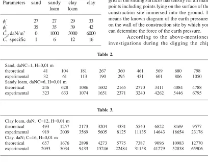
Table 1. The characteristics of soils
Parameters sand sandy clay clay loam loam
φ1° 27 27 29 33
φ2° 35 35 39 42
C2, daN/m2 0 1000 3000 6000 C, specific 1 6 12 16
Table 2.
Sand, daNC=1, H=0,01 m
theoretical 41 104 181 267 360 461 569 680 798
experimental 32 61 113 190 295 431 601 806 1050
Sandy loam, daNC=6, H=0,01 m
theoretical 246 628 1086 1602 2165 2770 3411 4084 4788
experimental 323 633 1074 1651 2371 3240 4262 5446 6795
Table 3.
Clay loam, daN; C=12, H=0,01 m
theoretical 493 1257 2173 3204 4331 5540 6822 8169 9577
experimental 919 2009 3569 5605 8125 11135 14643 18654 23176
Clay, daN; C=16, H=0,01 m
theoretical 657 1676 2898 4273 5775 7387 9096 10983 12770
experimental 2093 5034 9433 15246 22484 31158 41279 52858 65906
on the executive devices at an angle to the horizon which is equal to the angle of the internal friction of the soil. In the determination of the resistance to the digging the effect of the chip is not considered when it is introduced into the executive device or the drawing prism and raises a part situated there.
These experiments with color layers allow us to offer the following scheme for formation of the drawing prism (Fig. 3a, b and 4) at the final stage of the process of the digging:
• In the first case (Fig. 4a) the chip separated from the soil mass have such a thickness that its strength is sufficient for the introduction into the drawing prism and moving up along the surface of the blade. The chip puts the adjoining layers of the drawing prism in the motion. The part of the drawing prism AOSD rotates relative to the center the position of which is determined by the shape of the drawing prism, its height H, and the slope angle of the drawing prism. The part of the
prism ABO is stationary during the motion of the blade, but the soil layer which crumbles out of the rotating part of the prism moves along the surface BO at the angle of slope;
• In the second case (Fig. 4b) the chip has such thickness that its strength is not sufficient for introduction into the drawing prism. The soil chip is separated from the soil mass by the compacted core in front of the drawing prism. In this case the drawing prism is moved by blade as a solid body which acts as an executive device. It separates the chip from soil mass and accumulates a new prism of the developed soil.
In front of the bulldozer blade:
a)the digging depth which is sufficient for the introduction of the chip into the prism;
b)the small digging depth which is insufficient for the introduction of the chip into the prism;
As a result of the research the distribution in the soil of the sliding surfaces was identified (Fig. 5). The decision was very difficult. The sliding surfaces can destruct the soil. The problem is solved only by numerical methods with consideration for the weight of the soil. The line grid of the sliding surfaces has tensity for all main points including points lying on the surface of the construction site immersed into the ground. It means the known diagram of the earth pressures on the wall of the construction site by which you can determine the force of the earth pressure.
separated from the solid mass moves up along the executive device or inside it in the form of a monolithic body. Emerging the resistance forces to the chip movement have an indirect impact on the total resistance due to the increased resistance forces to the separation of the soil from the soil mass under kentledge ?o or p(y). The effect of the kentledge extends on the surface in front of the moldboard blade at a distance
a=h(tg +tg )/(tg tg ),
where the shift angle = /4- 2/2 is assumed as a constant depending only on the internal friction angle of the soil which is contrary to the limit equilibrium theory of the loosened and cohesive environment used by the authors in which the position and the shift surface geometries is not set in advance, but it is determined by solving the system of the differential equations of the equilibrium with certain strength conditions. At the same time it should be noted when the kentledge occurs on the surface of the cut soil, the change of the shift angle value should be expected.
The shift surfaces of the coarse cleavage shells (III) extend from the bottom part of the moldboard blade to the soil surface (Fig. 7). The shift surfaces of the fine cleavage shells (I and II) come about from the same place of the moldboard blade, but extend to the surface of the previously formed coarse cleavages before reaching the surface of the soil.
The inclination angles ( 1 and 2) to the horizon of the shift surface of the fine cleavage shells differ from the inclination angles of the coarse cleavage shells ( ). The change of the resistance to the digging during the movement of the moldboard blade at a constant cutting depth (h) is synchronized with the phenomena of the formation process of the soil cleavages. At the time of the formation of the fine cleavage shells the decrease of the resistance to the digging is observed and it is expressed by Pm (Fig. 7). At the time of the formation of the coarse cleavage shells the cutting force is reduced by a larger amount ?cl than the formation of the fine cleavage shells.
The component of the force of the resistance to the digging Pmin is a constant value at a permanent depth of the digging. It is the result of the sum of the resistances related to the processes:
• The soil compaction by the blunt edge of the moldboard blade by the value h?m (Figure 7) followed by its compaction into the wall;
• The overcome of the friction of the soil and the surface of the blunt edge of the moldboard blade is determined by the reaction of the elastic deformation of the compacted soil. The elastic deformation of the soil mass in front of the moldboard blade precedes to the plastic deformation of the shift or the separation of the soil cleavage element realized by the surface of the lower part of the moldboard blade which thickness is hd .
During the interaction of the blade with the soil mass the plastic deformation of the soil with the formation of the cleavage shells occur. The shift surface in relation to the soil mass does not always reach the surface of the soil. Only coarse cleavages reach the daylight surface. At the moment of the cleavages formation there is the maximum resistance to the digging. During the movement the elements of fine and coarse cleavages move together with the previous cleavages as one body along the moldboard blade surface and the shift surface (see. Fig. 7). The fine and coarse cleavages are observed at the bottom part of the moldboard blade. The plastic deformations spread from this moment. The elastic deformations of the soil mass precede to the plastic deformation of the soil mass. In the diagram the elastic deformation zone of the soil in the contact with the surface of the moldboard blade is shown by hd symbol. The elastic-plastic soil compaction into the mass is done by the blunt edge of the moldboard blade and it is expressed by h?m; hel -the elastic deformation in -the zone of -the soil compaction by the blunt edge.
the mass by the blunt edge and the lateral sides of the moldboard blade.
In this case the maximum value of the resistance to the digging should be determined by elastic deformation of the soil mass sufficient to achieve the above-mentioned plastic deformation. According to the experimental research data the separation of the chip from the solid mass occurs along the shift plane at the angle of . For this purpose it is necessary that in the soil mass the elastic deformation voltage reaches the sufficient value to overcome the resistance to the cleavage element formation. Before the cleavage formation in the soil mass of the elastically deformed state the radial compressive stress r occurs. The cleavage element shift occurs when the sum of the stresses acting on the shift plane intended at the angle of exceeds the resistance value to the element shift.
The diagram of the forces acting on the coarse cleavage element of the soil from the side of the moldboard blade and the surface of the soil mass shift is shown in Fig. 8. The daylight surface of the developed soil is horizontal for the convenience in the calculation scheme. The symbol G denotes the weight of the coarse cleavage element the value of which is determined by expression
= ℎ
2sin( + )
2sin sin ...(4)
where - a volume weight of the loosened soil kN/m3; b - a width of the moldboard blade in m; hcl h - a height of the cleavage element which is approximately equal to the depth of the digging because of the relatively small quantities hd ? hcm; - a soil cutting angle; - an inclination angle to the horizontal surface of the coarse cleavage.
A force Q influences on the cleavage element from above. It is a kentledge from the previously cleaved soil. The resultant forces of the normal N1 and friction F1=N1tg 1 have an effect on the cleavage element from the side of the moldboard blade surface
R1=N1cos 1,
where 1 - a friction angle of the moldboard blade surface.
The resultant forces of the normal N2 and friction F2=N2tg 2 have an effect on the cleavage element from the side of the soil mass
R2=N2Cos 2,
where 2 - a friction angle of the soil and soil. The traction force H1 of the moldboard blade surface and the traction force H2 of the soil surface effects on the cleavage element from the shift surface.
1= 1 ℎ sin , 2=
2 ℎ sin ,
where C1 is a traction of the soil surface and the moldboard blade and ?2 is a traction of the soil and the soil surface of the developed soil mass. According to the analysis of the calculation scheme with consideration for the above-mentioned forces the resistance to the cleavage is determined by the regularity
=( + )sin ( + 1)sin ( + 2)
sin ( + + 1+ 2)
+ (1+ 2) sin( + 2) sin( + 1) + (2ctg −1ctg )sin2( + 1)cos (
+ 2)sin ( + +ℎ
1+ 2)+ 1ℎctg .
...(5) If you do not take into account the soil traction and the moldboard blade surface and the soil mass surface (C1 =C2=0) and you do not take into account the value of the kentledge from the previous cut soil (Q =0), then the formula becomes a formula of G.N.Karasev [24].
The calculation scheme shown in Fig. 8 is used to determine the resistance force to the elastic deformation of the soil mass until the formation of the plastic deformation of the cleavage element separation
surface will be drawn through the point A perpendicular to r and define the value of the normal stress r, acting on the surface.
The displacement of the point A in the direction of radius r will be considered. The farther away from the point of application of the linearly distributed force Ref the point A will be located, the smaller its displacement will be. At the same value r the displacement of the points corresponding to the different angles will be different. The maximal displacement will be in the direction of the line of effect force Ref (at = 0). The displacement of the points will decrease with an increase of the angle , and the displacement of the points will be equal to zero in the limited plane (at = 90°). From these considerations it is assumed that the displacement of the point A in the direction of radius r is equal to
=( cos )
...(6)
where is the coefficient of proportionality. It is supposed that point A has displaced to point B at a distance dr. The deformation er in the relation to the segment dr will be defined. The displacement of the point ? like the previous one is defined by the expression
=( cos )
( + ) ...(7)
Then the relative deformation of the segment is equal to dr
=( − )= −( + ) cos =( 2cos+ )
...(8)
Neglecting the value rdr in the denominator of this expression which is insignificant in comparison with r2,we obtain
=( cos )2
. ...(9)
And since between the stress and strain the direct proportionality is taken, the value of the radial stress which causes the relative compression of the considered element will beequal to
= cos2
, ...(10)
where is a proportionality factor. The product of coefficients is determined by the equilibrium conditions. To compile the equilibrium equations and to determine the voltage r the section of the half-cylinder which axis coincides with the cutting edge of the moldboard blade will be considered. The sectional plane of semi-cylinder is perpendicular to the force vector Ref crossing the cylinder axis. Across the surface of the semi-cylinder compressive stresses r will be applied. The value of the compressive stresses is expressed by the above-mentioned formula. The value of the strain is considered equal to the elementary area with the width dl corresponding to the central angle d and radius r. From the equilibrium condition it follows that the sum of the projections of all forces in the direction of the vector Ref which is perpendicular to the plane bounding linearly deformable soil mass must be equal to zero, i.e.
− 2 cos = 0
0 2
0
Substituting the value r, we get
2 cos2 = cos sin + 2
0
Considering
=2 cos2 ,
2
0
Obtain
=
2 . ...(11)
From this expression we define the product of the coefficients
=2
=2 cos .
...(13)
Now the diagram of forces applied to the coarse elements of cleavage will be considered. The shift surface of the cleavage reaches the daylight surface of the soil mass. At the time preceding the process of cleavage element separation from the soil mass plastic deformation emerges along the shift surface oriented at an angle to the surface (Fig. 9a). The rest of the soil mass is deformed elastically as indicated by many researchers in their works [24, 25].
To implement of the plastic deformation of the separation of the coarse element of the cleavage at the angle it is necessary to overcome the resistance of the forces of friction and cohesion in the shift plane as well as the weight of the cleavage element G and kentledge Q from the previous cut-off soil. The diagram in Fig. 9 b shows the resulting vector R corresponding to these resistances. The value of this force vector is determined according to the calculation model by the expression
= 22+ ( 2+ 2)2
...(14) where
2=
( + ) sin( + 1) cos 2
sin( + + 1+ 2) ;
2=
( + ) sin( + 1) sin 2
sin( + + 1+ 2) ;
2= 2
ℎ
sin .
The direction of the vector operation with respect to the cleavage plane is characterized by the angle between the vector R and the cleavage plane of the shift element defined by the expression
= arcsin 2.
The plastic deformation is preceded by the elastic deformation in the process of which the potential energy is accumulated. The part of the energy is releases in the course of the implementation of the plastic deformation. This potential energy of the elastic deformation of the soil mass is created by the radial compressive stresses in the angular range between the shift surface and angle characterized , and the plane
bounding the linear deformable soil mass, i.e. the plane defined by the angle ( + 1) in Fig. 9 a. The angle varies in this range from = + 1+ - /2 to = /2. The amount of projection of the radial compressive stresses r( ) in the specified angular range in the direction of the operation of the vector R provides the fulfillment of its value sufficient for the plastic deformation of the cleavage element separation of the soil at an angle . In this case, the following equation can be written,
= cos − ( − ) =
2
0
cos + ( − ) , 2
0
...(15) where = + 1+ - /2.
Substituting the value in this expression r=(2Refcos )/( rl) we obtain the equation
=2 cos cos( + + )
2
After solving the integral and the corresponding transformations we obtain
= sin( + + 1+ 2) − − 1− + 0,5 sin 2( + 1+ )
−cos( + + 1+ ) sin2( + 1+ )
We introduce
=sin( + + 1+ ) − − 1− + 0,5 sin 2( + 1+ )
−cos( + + 1+ ) sin
2( +
1+ )
.
Then we have
=
...(16)
As a result we have the formula for determining the maximum value of cutting resistance and the resistance to the elastic deformation of the soil mass
= sin ( + 1)
...(17)
=
( + )2sin2( +
1) cos2 2
sin2( + + 1+ 2)
+ ( + ) sin( + 1) sin 2 sin2( + + 1+ 2) +
2 ℎ
sin
2
...(18) For the case of cutting of the loosen soil when C1=C2=0
= ( + ) sin2( + 1) sin( + + 1+ 2)
...(19) The total resistance to the cutting with the resistance to the cleavage and the soil compression by the cutting edge of the moldboard blade without the resistance to the formation of the side cleavage shells for flat blades without teeth is determined by the dependence
=sin( + 1)
( + )2sin2( +
1) cos2 2
sin2( + +
1+ 2) +
( + ) sin( + 1) sin 2
sin2( + +
1+ 2) + 2ℎ
sin
2
+
+0,5 tg ( − sin
1) + cos( − 1)
...(21)
Main results
The results of the analysis of the obtained formula are given in comparison with the results of calculations by the empirical formula of Professor A.N.Zelenin. The calculations were madefor a variety of soils which characteristics are shown in Table-1 for the case of the kentledge lack Q=0.
The dependence of the cleavage angle from the cutting angle is shown in Fig.11. It means that the soil cleavage angle for different soils decreases when the cutting angle increases. The meaning of the cleavage angle presented in this graph corresponds to the minimum resistance of the soil chip separation from the soil mass, i.e, the minimum energy consumption of the soil cutting process.
The dependence of the resistance to the cutting of sand, sandy loam, clay loam, and clay from the angle of the cutting by blade with width of 1 m to a depth of 0,01 m is shown Fig. 11-12. The graph also shows the value of the cutting resistance calculated by the formula of Professor A.N.Zelenin, which corresponds to the results of experimental studies. The results of the theoretical calculations (table 2, 3) correspond to the soil cleavage angle according to the schedule defined by = f ( ) (Fig. 11). It should be noted the
satisfactory convergence of the results of comparison of the calculated and experimental cutting resistance of various soils in the range of the cutting angle from 30° to 70° corresponding to the practical range of applied angles of cutting for the blades of the executive devices of the earthmoving machinery.
The graphs of the change in resistance to cutting soil depending on the depth of the cut with a blade at the cutting angle of 300 and with the width of 100 cm are shown in Fig. 12. The calculated data with the use of the theoretical formula are compared with experimental data obtained by calculation according to the empirical formula of Professor A.N.Zelenin. Analyzing these materials it is necessary to state the good and satisfactory convergence of matched data for the relatively soft soils (sand and sandy loam) with the number of strokes of the dynamic densitometer F having from 1 to 6 strokes, and the significant difference for the solid soil (loam and clay) with the number of strokes F from 12 and above.
CONCLUSION
1. The analysis of the experimental data and their comparison with theoretical calculations show a systematic difference in the comparison of data suggesting the need for the further theoretical studies to clarify the mathematical models. 2. The phenomenon of the formation of the lateral cleavage at the edges of the blade which is typical for strong soils is not reflected in the developed mathematical model compared with the practical results.
REFERENCES
1. The Planetary Vibroexciter with Elliptic Inner Race. // N. Surashev, D. Yelemes, A. Kalieva, Dudkin M.V. // Trans Publications, Switzerland, Advanced Materials ResearchVols. 694-697 (2013), pp 229-232.
2. Contact Force Calculation of the Machine Operational Point.// S.Yu.Pichugin, M.V. Dudkin, S.N. Fadeev// Life Science Journal (ISSN:1097-8135), Richmond Hill, New York 11418, the United States. 2013;10(10s):246-250. 3. The Analysis of Road Machine Working Elements Parameters.// S.Yu.Pichugin, M.V. Dudkin, S.N. Fadeev// World Applied Sciences Journal 23 (2): 151-158. 2013 (ISSN / E-ISSN: 1818-4952/1991-6426). IDOSI Publications, 2013.
4. Studying the Machines for Road Maintenance./ / S.Yu.Pichugin, M.V. Dudkin, S.N. Fadeev// Life Science Journal (ISSN:1097-8135), Richmond Hill, New York 11418, the United States. 2013;10(12s):134-138.
5. Calculation of the Interaction of Working Body of Road Machine with the Surface.// A.V. Vavilov, S.Yu.Pichugin, M.V. Dudkin, S.N. Fadeev// Life Science Journal (ISSN:1097-8135), Richmond Hill, New York 11418, the United States. 2013;10(12s):832-837.
6. Balovnev V.Y. Àvtomobili i traktory. Êratky spravochnik. - Moskva-Îmsk: Izd-vo SibADI, 2008. - 383 s.
7. Balovnev V.Y., Glagolev S.N., Danilov R.G., Kustarev G.N., Shestopalov Ê.Ê., Gerasimov Ì.D. Mashiny dlya zemlyanih rabot: êonstrukcya, raschet, potrebitelckie svoistva.-Belgorod: Izd-vo BGTU, 2011.-401 s. 8. Gruzin À.V., Gruzin V.V., Abramenkov E.À.
Gruntjvye sredy v uslovyah staticheskogo I dinamicheskogo nagruzhenya: monografia.-Îmsk: Izd-vo ÎmGTU, 2009.-140 s.
9. Goryachev M.G. Raschet proizvoditelnosty mashin dlya stroitelstva, remont i soderzhanya gorodskih putey soobshenia. – M.:ÌÊLP, 2003.-36 s.
10. Lutov V.N. Sartakov A.V. Kompleksnaya mehanyzacya tehnologicheskih processov v stroitelno-dorozhnom proizvodstve: uchebnoe posobie// Alt.gos.tehn.un-t im. Y.Y.Polzunova.-Barnaul: Izd-vo AltGTU, 2011. – 166 s.
11. Stroitelnye mashiny: ucheb.posobie / D.E. Abramenkov [i dr.]; pod red. B.G. Kima. – Vladimir: Red.-izdat. Kompleks VlGU, 2004.-190 s.
12. Sokolov G.K. Tehnologia stroytelnogo proyzvodstva: ucheb. Posobie dlya vuzov po napravlenyu 270100 “Str-vo”/ G.K. Sokolov. – 3-e izd., ster. – M.: Akademia, 2008, - 539 s.: il. 13. Kudryvcev E.M. Oformlenie diplomnogo proekta na komputere: ucheb. Izdanie /E.M. Kudryvcev. –M.: Izd-vo Associacii stroitelnyh vuzov, 2006. – 226 s.
14. Charles J., Bernhardsson S. Les Editions de Physique. 1992. P. 863.
15. Turnbull A., Francis P.E., Ryan M.P., Griffiths A.J., Orkney L.P., Hawkins Â. // Corrosion. 2002. V. 58. P. 1039.
16. Verneau M., Lojewski C., Charles J. // Duplex Stainless Steels 91. / Eds.
17. Berestov Å.I. Nauchnye osnovy modelirovanya sistemy “grunt-rabochie organy zemleroinyh mashyn” v rezhime posloinoi razrabotky: Avtoref. dis. d.t.n. Mogilev, 1998.
18. Zelenin À.N., Balovnev Â.Y., Kerov I.P. Mashiny dlya zemlyanyh rabot.– Ì.: Ìashinostroenie, 1975.– 423 s.
19. Permykov V.B. Kompleksnaya mehanizacia stroitelstva: uchebnik dlya vuzov po napravleniyu “Str-vo”/ V.B. Permykov. – Izd. 2-e, ster. – M: Vysh. Shk, 2008. – 382 s.: il. 20. Karlsson L. // Welding in the World. 1999. V. 43.
P. 20.
21. Josefsson Â., Nilsson J.O., Wilson A. // Proc. Duplex Stainless Steels’91. Les Editions de Physique. Les Ulis Cedex. France. 1991. P. 67. 22. Polosin M.D. Mashinyst dorozhnyh I stroitelnyh: ucheb. Posobie dlya nach. prof. obrazovania / M.D. Polosin. – M.: Izdatelskii centr “Akademia”, 2002. – 288 s.
23. Stanevski V.P., Khmara L.À., Kolesnikov N.P., Modernizacya I povyshenie proizvoditelnosty stroitelnyh mashyn.– Êiev: Budivelnik, 1992.– 152 s.
24. Êàrasev G.N. Vybor osnovnyh parametrov pricepnogo screpera. Dissertacya na soiskanie uchenoi stepeny kand. tehn. nauk. M., MADI, 1970.