Design and Simulation of Microstrip Phase Array
Antenna using Circular Patches
Osama Siddique
Facilities Manager, Alshaya Trading Company Limited
Riyadh, Saudi Arabia
Muhammad Kamran
Khattak
Asst. Chief Engineer, Pearl Continental Hotel Peshawar, KPK, Pakistan
Waqar Ahmad
Team Leader TransmissionDepartment, Innovative Engineering Services Private Limited
Islamabad, Pakistan
Saleh Alshomrani, Ph.D
Faculty of Computing and IT King Abdulaziz University
Jeddah, Saudi Arabia
Irfanud Din
PhD Scholar Incheon National University
Incheon, South Korea
Shehram Akram
Faculty of Computing and IT, North Jeddah
King Abdulaziz University Jeddah, Saudi Arabia
ABSTRACT
Microstrip antennas are used in variety of wireless applications including radars, cellular phones, wireless sensor networks, and in medical applications. The objective of this research is to design a circular patch microstrip phase array antenna which can resonate at UHF i.e. 10 GHz and later on improve the design and include phase steering in this design. Two circular patches with radius of 5.83 mm each are used in this design. The proposed antenna is excited through coaxial probe feed using Wilkenson power divider rule.
ADS Momentum software is used to simulate the proposed antenna. Various parameters for example S11 Parameter, return losses, directivity, efficiency and gain of the proposed antenna is also obtained using ADS Momentum.
General Terms
Array Antenna, Microstip Array Antenna, Circular Patches, Wireless Applications.
Keywords
Microstrip phase array antenna, Circular patch antenna, ADS Momentum.
1.
INTRODUCTION
Microstrip antennas [1] are currently one of the fastest growing antennas in telecommunication industry. Research has been carried out in the recent past to improve the performance and efficiency of these patch antennas. Rapid development in patch antennas started in 1970 and by the end of 1980s, the idea of using microstrip array antenna in wireless communication was well established. The light weight, reduced size, phase steering ability, ease of installation, low cost and possibility of integration of patch antennas make this antenna to be the best choice of researchers and manufacturers [2].
Wireless communication has experienced good growth in the past few years [3] since it allows users to access network services without being tethered to wired infrastructure. The most famous point to point communication technologies that have evolved are wireless local area networks (WLANs) known as 802.11 and the blue tooth technology known as 802.11a. Antenna plays a very important role in the
functioning of these two technologies since it is expected to provide wireless transmission between the two points. A good antenna will be able to indicate good signal to noise ratio and immunity to noise. Antenna in microwave links will portray compact structures and ease of construction to be mounted on various wireless devices. Considering all these parameters, microstrip antenna (being low profile) is very much required [4].
Along with advantages, microstrip antenna has several disadvantages [5] such as low gain, narrow bandwidth and low efficiency but these problems can be overcome by intelligent designs i.e. by constructing many patch antennas in an array configuration.
2.
LITERATURE REVIEW
2.1
Antenna Design
Fig. 1: Proposed Design of Circular patch Array Antenna
2.2
Basics of Transmission Line Theory
Transmission lines and waveguides are conduits for transporting RF signals between elements of a system. For example transmission lines are used between an exciter output and transmitter input, between the transmitter input and its output and between the transmitter output and the antenna [6]. Transmission lines are complex networks containing the equivalent of all the three basic electrical components: resistance, capacitance, and inductance. Hence, transmission lines must be analyzed in terms of an RLC network [6].
2.3
Antenna Arrays
Usually the radiation pattern of a single element is relatively wide, and each element provides low values of directivity (gain). In many applications, it is necessary to design antennas with very high directive characteristics (very high gain) to meet the demands of long distance communication. [7] This can only be accomplished by increasing the electrical size of the antenna [8]. Enlarging the dimensions of single elements often leads to more directive characteristics. Another way to enlarge the dimensions of the antenna, without increasing the size of individual element, is to form an assembly of radiating elements in an electrical and geometrical configuration. This new antenna antenna formed is referred to as an array [8]. The antenna arrays are of vast importance and are widely used nowadays for various purposes like military, missiles and satellite communication. [9] There are different forms of antenna arrays linear, circular, planar etc. The radiation pattern of an array antenna is mostly considered in the far field, where the field depends on two parameters. One is the distance r of the reciever and the other deals with the spherical coordinates θ and φ. The radiation pattern of an antenna can be calculated by :
Array Pattern = Array element pattern * Array factor(AF) (16) The array factor determines the overall radiation pattern of the array while the element pattern describes radiation pattern of the individual element [8]. The array factor can also be defined as “The function of the total number of elements, their
spacing and the phase difference between each element” [10]. The array factor for a uniform antenna can be written mathematicaly as:
(17)
One may normalise the array factor so that the maximum value is equal to unity.
(18)
2.4
Mutual Coupling in Antenna Arrays
One of the basic characteristics of an antenna array appears when two or more elements are located near to each other and effect each other [8]. The amount of coupling depends on the following:
Radiation characteristics.
Actual separation between elements .
Relative orientation of elements.
The mutual coupling between two radiating elements depends upon the distance between them. [11] If they are close to each other the mutual coupling will be greater. Thus energy is transferred between elements and this is called mutual coupling. One can say that the electromagnetic coupling between the elements is mutual [12].
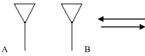
The transmitting mode coupling can be shown with the help of Fig. 4. Two antennas, A and B are placed relative to each other. Antenna A is excited by a source and radiates. When this radiation reaches antenna B, it excites antenna B and rescatteres some the energy back to antenna A. Antenna A recieves the energy again and so on. The total contribution that an element makes to the far field pattern does not depend on its own excitation from the generator only, but also upon the total parasitic excitation due to which coupling is introduced to other generators [13]. The mutual coupling phenomenon is reciprocal in nature. If one antenna is used as a transmitter and the other as a reciever or vice versa. Both is the same.
A B
Figure 1: Mutual Coupling Mechanism.
Since mutual coupling in phased array antennas can affect the radiation pattern so consideration should be given to this mechanism.
3.
SIMULATION SETUP THROUGH
ADS MOMENTUM
3.1
Introduction to ADS Momentum
tool for prediction of the performance of high frequency circuit boards, antennas and integrated circuits [14].
The ADS Momentum optimization tool extends Momentum capability to a real design automation tool. The Momentum Optimization process varies geometry parameters automatically to help in achieving the optimal structure that for the circuit or device performance goals. Momentum optimizations can be done by using layout components (parameterized) from the schematic page.
One of the great advantages that Momentum possesses is the 3-dimensional interface that it provides for the user during simulations and results. Momentum is a 2.5D solver that can do both 2D and 3D computations. For example while computing the antenna parameters, Momentum provides both 2D and 3D graphs of the directivity and the far-field radiation patterns of the antenna.
3.2
Applications of Momentum
ADS Momentum can be used as follows [14].
ADS Momentum is applicable when no analytical model exists for the circuit. Momentum co-simulates with ADS and performs the required tasks.
ADS Momentum can be used to determine coupling effects.
ADS Momentum can calculate narrow resonances within the circuit model which cannot be found with analytical models.
ADS Momentum can be used to display the radiation patterns and far field radiation plots for antennas etc.
ADS Momentum can show the current pattern and current densities within the circuit.
Momentum can be used for the CPW (Co Planar Waveguides) results with no slot mode.
Momentum can be used to optimize or modify the geometry of the passive layouts to achieve the desired results.
3.3
Method of Calculation
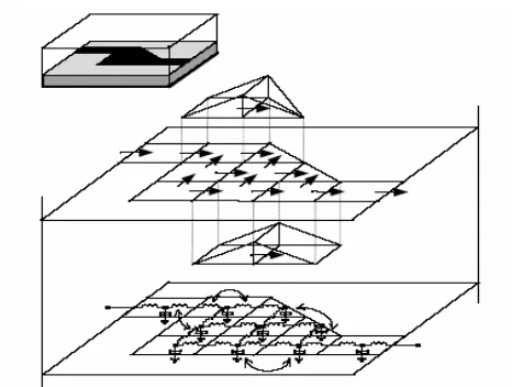
The method of simulation that is used by ADS Momentum is called the Method of Moments which is based on the integral formulation of Maxwell’s equations, simulating the circuit with matrix equations. Fig. 13 shows the stepwise simulation of a circuit by ADS Momentum. Where a known circuit is first simulated and then divided into mesh strip, wires with rectangles and triangles (arbitrary surface meshes). The next step is to model the surface current in each current cell i.e. linear distribution. The final step is to solve a mesh matrix equation and calculate S-parameters.
Figure 2: Stepwise simulation of ADS Momentum.
3.4
Theory of Operation for Momentum
Momentum is based on a numerical discretization technique called the Method of Moments. This technique is used to solve the Maxwell equations for planar structures embedded in multilayer dielectric substrates. Momentum uses two different modes of simulation which are based on the Method of Moments. The first one is the microwave, or full wave, mode of simulation and the second one is the RF, or quasi-static, mode of simulation. The application and formulation of the Green’s function is the main difference between these two methods.
Momentum, or the full wave simulation mode, uses the full wave Green’s function. The Full wave Green’s function is frequency dependent and it fully characterizes the substrate without making any further approximations. This formulation results in the L and C elements that are complex and frequency dependent as shown in Fig. 13. The RF, or quasi-static, mode uses a frequency independent Green’s function which results in L and C elements which are complex but frequency independent. As this mode is not frequency dependent, the quasi-static mode only approximates the solution of the network (L and C) for the first frequency simulation point and hence the RF mode runs much faster than the Momentum mode. The simulations also show that the quasi-static mode should be used for structures that are smaller than half a wavelength [14].
Both the engine modes use the star-loop basis function that ensures a stable solution at all frequencies. Both the modes use the mesh reduction algorithm which helps in reducing the number of unknowns when dividing the design into polygonal meshes. This function can be turned on or off [14].
Excitation of the networks is fed through the input port. The currents in the equivalent network model are given by unknown amplitudes in the rooftop expansion model. The amplitudes are obtained by solving for the unknowns in the rooftop expansion. The S-parameters are extracted with the help of the port calibration process.
3.5
Simulation Techniques Used in ADS
In addition to the “auto-select mode”, ADS uses three different matrix solution techniques which are explained as following.
In this method, the matrix N is stored in a dense matrix format which requires memory space of order N2. This matrix is then solved by the direct matrix factorization technique. This method requires N3 order for solution (computer time). The direct dense matrix solver has a predetermined number of operations. The main disadvantage of this method is that it requires cubic computer time to solve dense matrices of the order N. Hence it requires larger time for complex problems [14].
Iterative Dense Method
In this method, the matrix N is stored in a dense matrix format which requires N2 memory space while the matrix N is solved using iterative matrix solver technology. This solution method requires N2 order to solve the matrix, hence scaling the computer time to quadratic (N2) from cubic (in the direct dense method). This yields shorter simulation time for larger problem sizes [14].
Convergence of the iterative technique is the main drawback of this method of simulation because iterative methods do not converge quickly in large and complex problems. The ADS monitors the convergence rate and automatically jumps to the direct dense method of simulation when it detects stagnancy in the convergence [14].
Direct Compressed Method
Direct compressed method (DCM) is one of the latest techniques used for matrix solution. DCM is also known as the FMM (Fast Multipole method) and is considered to be one of the top ten algorithms of the 20th century. In this method, the matrix is stored in a compressed matrix form which requires NlogN memory space while it is solved using direct compressed matrix factorization technique. The direct compressed factorization technique requires (NlogN)1.5 computer time [15].
The computer time that this method requires is linear logarithmic with matrix size N which makes this method most useful for the solution of large and complex problems. This method reduces both the simulation speed and the memory allocation space required for the simulation [14].
All these three type of methods are available in ADS. Generally the default settings of the ADS are set to auto-mode but user can change the type of simulation manually. ADS is sensitive to the type of problem and chooses proper simulation method according to the problem, so the preferable way to use ADS is to keep the settings on auto-mode.
4.
SIMULATION RESULTS USING ADS
The proposed antenna was designed and simulated in ADS (Advance Design System) Momentum, which is a 3D electromagnetic solver which can compute S-parameters for general planar circuits which includes microstrip, slot line, strip line, coplanar waveguides and many other topologies. One of the great advantages that Momentum possesses is the 3-dimensional interface that it provides for the user during simulations and results. Momentum is a 3D solver that can do both 2D and 3D computations. For example while computing the antenna parameters, Momentum provides both 2D and 3D graphs of the directivity and the far-field radiation patterns of the antenna, S11 (input reflection coefficient) Parameter and also the VSWR (Voltage Standing Wave Ratio). Following
are some simulation results of the proposed antenna shown in Fig. 1.
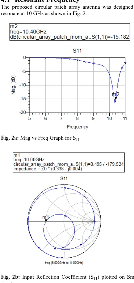
4.1
Resonant Frequency
The proposed circular patch array antenna was designed to resonate at 10 GHz as shown in Fig. 2.
Fig. 2a: Mag vs Freq Graph for S11
Fig. 2b: Input Reflection Coefficient (S11) plotted on Smith chart
4.2
Radiation Pattern
Fig. 3a: 3D Radiation pattern
Fig. 3b: 3D Radiation Pattern in EMDS
4.3
Gain and Directivity
The 2D graphs of Gain and Directivity is shown in Fig. 4 showing that the maximum Gain and Directivity is in between 60 º and 120 º.
Fig. 4: Gain and Directivity of the proposed array antenna
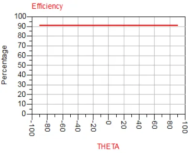
4.4
Efficiency
Fig. 5 shows that the efficiency of the proposed antenna is approximately 90% which is much better than the efficiency of single circular patch or rectangular patch.
Fig. 5: Efficiency of the proposed array antenna
4.5
Radiated Power
Fig. 6 shows that maximum radiated power of the proposed antenna is in between 60 º to 120 º.
Fig. 6: Radiated ower of the proposed antenna
5.
CONCLUSION
All the simulation results show that the microstrip phase array antenna performs better than the single circular patch or the single rectangular patch antenna. The radiation pattern of the microstrip array antenna is far better than the single circular or the single rectangular patch. The main beam is broadside i.e. between 90º and 270º with nulls at 0º and 180º. Similarly the efficiency, directivity and gain of the array patch antenna is better than the single patch. All these simulations lead to the conclusion that the number of patches in an array is directly proportional to the efficiency, directivity and gain of the antenna. If we increase the number of elements in the array, the radiation pattern will improve further.
6.
REFERENCES
Waveguide Transition with Slot Radiators. Proceedings of ISAP2012, Nagoya, Japan, 2012.
[2] A C. A. Balanis, Antenna Theory, 3rd edition, John Wiley, New York, 2005.
[3] Adnan Aijaz, Hamid Aghvami, andMmojdeh Amani. A survey on mobile data offloading: Technical and Business Perspectives. Wireless Communications,IEEE. Volume:20 , Issue. 2013
[4] M. K. A. Rahim, A. Asrokin, M. H. Jamaluddin, M. R. Ahmad, T. Masril and M. Z. A. Abdul Aziz, “Microstrip Patch Antenna Array at 5.8 GHz for Point to Point Communication,” International RF and Microwave Conference Proceedings, pp. 216-219, Malaysia,
September 2006.
[5] Naresh Kumar Poonia, Krishan Kumar Sherdia. Microstrip Antenna Array for WiMAX & WLAN Applications. International Journal of Advanced Research in Computer and Communication Engineering. Vol. 2, Issue 9, 2013
[6] J. J. Carr, Practical Antenna Handbook, fourth edition, McGraw-Hill, New York, 2001.
[7] Constantine A. Balanis. Antenna Theory: Analysis and Design. John Wiley and Sons. 2005, pp. 283
[8] S. N. Makarov, Antenna and EM Modeling with
MATLAB, JohnWiley, New York, 2002.
[9] Godara, L.C. Applications of antenna arrays to mobile communications. I. Performance improvement, feasibility, and system considerations. Proceedings of the IEEE Volume:85 , Issue: 7 .1997
[10]R. Iwata and S. Chen, “Mutual Coupling Effects in Microstrip Patch Phased Array Antenna,” IEEE Antennas and Propagation Society International Symposium, pp. 1028-1031, New York, August 2002.
[11]Sonam Aggarwal and Anupma Marwaha. Effects of Mutual Coupling on Various
[12]L. Allen and L. Diamond, “A Simple Model for Mutual Coupling Effects on Patterns of Unequally Spaced Arrays,” IEEE AP-15, pp. 530-533, 1967.
[13]N. Misran and M. T. Islam, “Broadband E-H Shaped Microstrip Patch Antenna for Wireless Systems”, PIER,
pp. 163-173, Malaysia, 2009. [14]ADS built in manuals and online help.
[15]R. Caifman, V. Rokhlin and S. Wandzura, “The Fast Multipole Method for the Wave Equation: A Pedestrian Prescription,” IEEE AP-35, pp 1-12, June 1993.
[16]Parameters of Two Element Circular Patch Microstrip Antenna Array. International Journal of Application or Innovation in Engineering & Management (IJAIEM). 2013
[17]A. Keshtkar, Ah. Keshtkar and A.R. Dastkhosh, “Circular Microstrip Patch Array Antenna for C-Band Altimeter System,” International Journal of Antennas and Propagation, Hindawi Publishing Corporation, Vol. 2008, pp. 01-07, 2008.
[18] H. Iizuka, K. Sakakibara, T. Wantanabe, K. Sato, “Millimeter-Wave Microstrip Array Antenna with High Efficiency for Automotive Radar System,” R&D Review of Toyota CRDL, Vol. 37, No. 2, pp. 7-12, April 23, 2002.
Osama Siddique is working as Facilities Manager in Alshaya International Trading Co. Riyadh Kingdom of Saudi Arabia. He has done his Master of Science in Electrical Engineering from Linnaeus University Vaxjo Sweden and Under graduation in Computer Systems Engineering from University of Engineering & Technology Peshawar Pakistan. Siddique's main research areas are Array Antennas, MIMO antennas and Singnal Processing Antennas.
Muhammad Kamran Khattak is working as Asst. Chief Engineer at Pearl Continental Hotel in Pakistan, leading the Building Automation Systems in R & D section along with the electromechanical up gradations, energy conservation and sustainability projects. He had also worked as Research Associate at GIKI which is one of the leading technical universities of Pakistan. He is a post graduate Electrical Engineer specialized in Signal Processing and Wave Propagation. He completed his masters degree from Linnaeus University Sweden. He also holds a bachelors degree in Electrical Engineering from University of Engineering and Technology, Peshawar, Pakistan. His prime area of research includes Microstrip Antennas, Wireless Sensor Networks, Body Area Network, Building Management System (BMS) and Condition Monitoring System (CMS).
Waqar Ahmad is currently working with IES(Innovative Engineering Services).pvt ltd Islamabad as a Team leader at the Transmission Department. he obtained his Masters degree in Electrical Engineering with specialization in signal processing and wave propagation from Linnaeus Universty Vaxjo Sweden. he has done his graduation in Computer software engineering from UET Peshawar. His main area of research includes Microstrip Patch Antennas and Computer Networking.
Dr. Saleh AlShomrani is an Associate Professor of Information Systems Department at King Abdulaziz University. He is also serving now as the Vice-Dean of Faculty of Computing and Information Technology,– North Jeddah Campus at King Abdulaziz University. He earned his Bachelor degree in Computer Science (BSc) from King Abdulaziz University, Saudi Arabia 1997. He received his Master degree in Computer Science from Ohio University, USA 2001. He Also earned his Ph.D. in Computer Science from Kent State University 2008, Ohio, USA, in the field of Internet and Web-based Distributed Systems and Technologies, and he is actively working in this area.
Irfanud Din did his BSc (2004) in Computer Systems
Engineering from University of Engineering and Technology, Peshawar, Pakistan and his MSc (2011) in from Myongji University, South Korea. Currently he is pursuing his PhD from Incheon National University, South Korea. his research interests include green wireless communication wireless sensor networks and next generation cellular networks.