ORIGINAL ARTICLE
Han-Min Park · Masami Fushitani · Hee-Seop Byeon
Derivation and application of an equation for calculating shear modulus of
three-ply laminated material beam from shear moduli of individual laminae
Abstract In a detailed study of the relation between the defl ection caused by shear force and the constitution of a laminated material beam, we derived an equation for calculating the shear modulus of a laminated material beam from the shear moduli of individual laminae. The validity of the derived equation was investigated using cross-laminated wood beams made with fi ve species. The calcu-lated shear moduli parallel to the grain of face laminae ranged from 48.3 MPa to 351 MPa, while those perpendicular to the grain of face laminae ranged from 58.0 MPa to 350 MPa. The calculated shear moduli increased markedly with increasing shear modulus in a cross section of perpendicular-direction lamina of a cross-laminated wood beam. The calculated apparent modulus of elasticity (MOE) of cross-laminated wood beams agreed fairly well with the measured apparent MOE values. This fact indicated that the apparent MOE of cross-laminated wood beam was able to be calculated from the true MOE values and shear moduli of individual laminae. The percentage of defl ection caused by shear force obtained from the calculated apparent MOE (Ysc) was close to that obtained from the measured apparent MOE (Ys) and there was a high correlation between both values. From the above results, it was concluded that the derived equation had high validity in calculation of shear modulus of a cross-laminated wood beam.
Key words Three-ply laminated material beam · Shear modulus · Modulus of elasticity · Shear force · Defl ection
H.-M. Park (*) · H.-S. Byeon
College of Agriculture, Institute of Agriculture and Life Science, Gyeongsang National University, Jinju 660-701, Republic of Korea Tel. +82-55-751-5503; Fax +82-55-762-5999
e-mail: [email protected]
M. Fushitani
Faculty of Agriculture, Tokyo University of Agriculture and Technology, Fuchu, Tokyo 183-8509, Japan
Introduction
When loads are applied vertically to a beam, bending moment and shear force are exerted on it. In the case of four-point loading, shear force and bending moment are exerted between the loading point and the supporting point. The defl ection caused by shear force is contained when the defl ection at midspan between the supporting points is measured as specifi ed in Japanese Agricultural Standards for glued laminated wood1
and laminated veneer lumber.2 It was found by the authors3,4
that the modulus of elasticity (MOE) parallel to the grain of face lamina of three-ply cross-laminated wood made with sugi wood was mark-edly infl uenced by the defl ection caused by shear force. Furthermore, to improve the strength performances of laminated wood beams, parallel-laminated and cross-laminated wood beams were manufactured from fi ve species with different densities and shear moduli in cross section, and we investigated the effect of defl ection caused by shear force on the static bending strength performance. As a result, it was found that the modulus of rupture as well as the MOE parallel to the grain of face laminae decreased owing to an increase in defl ection caused by shear force with decreasing shear modulus in the cross section of the core lamina.5
Apparent defl ection is composed of the defl ections caused by bending moment and shear force, and the per-centage of defl ection caused by shear force is in proportion to MOE/shear modulus (E/G). Because E parallel to the grain of face laminae is great and G is very small for three-ply cross-laminated wood beams made with sugi,3–5
E/G is markedly increased. For sugi wood–aluminum hybrid composite beams,6 E/G is also increased because E is con-siderably large and G is not.
The defl ection caused by shear force of laminated mate-rial beams was obtained by subtracting the defl ection caused by bending moment from the apparent defl ection, and the percentage of defl ection caused by shear force was inve-stigated. Furthermore, to adopt a detailed approach to the relation between the defl ection caused by shear force Received: August 4, 2008 / Accepted: December 19, 2008 / Published online: March 12, 2009
and the constitution of the laminated material beam, it is necessary to derive an equation for calculating the shear modulus of the laminated material beam from the shear moduli of individual laminae, like the MOE.
In this study, we derived an equation for calculating the shear modulus of a three-ply laminated material beam from shear moduli of individual laminae. The validity of the derived equation was investigated using cross-laminated wood beams made with fi ve species, which we reported in a previous article.5
Derivation of equation to calculate shear modulus of
three-ply laminated material beam
Shear stress
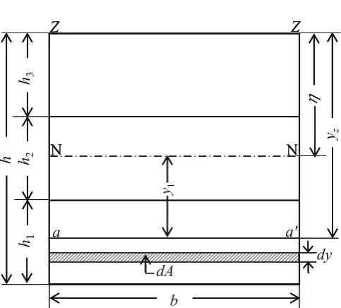
Figure 1 shows the confi guration of cross section for obtaining the shear stress and shear strain of a three-ply laminated material beam. Shear stress t that occurs in a three-ply laminated material beam is expressed by the following equation:7
τ = ( )
( )
=
=
∑
∑
F E S
b E I
i i
i r
i i i
1
1
3 (1)
where F is the shear force; Ei is the MOE of the ith lamina; Si is the geometrical moment of area of cross section of the ith lamina about the neutral axis NN; b is the width of lamina; Ii is the geometrical moment of inertia of cross
section of the ith lamina;τ = ( )
=
∑
E Si i ir
1
means the sum only
for the layer lower than horizontal line aa′ of cross section in which we want to obtain shear stress t.
The distance from the base axis ZZ to neutral axis NN (h) is given by the following equation:7
η = = ( )
=
∑
∑
E S
E A
i i
i
i i
i
z 1 3
1
3 (2)
where (Si)z is the geometrical moment of area of cross section of the ith lamina about the base axis ZZ; Ai is the
cross-sectional area of the ith lamina. Hence, from Eq. 2, the distance from the base axis ZZ to neutral axis NN (h) can be derived as
η =
−
(
)
+(
− −)
+− − + +
1 2
2 2 2
2 2 2
1 1 1
2
2 2 1 2 2
2 3
2
1 2 1
2 1
E hh h E hh h h h
E h h h h h h h hh h
E h E h E h h h
2 2
2
1 1 2 2 3 1 2
+
(
)
+ + ( − − ) (3)
where E1, E2, and E3 are the MOE values of individual laminae of a laminated material beam; h1, h2, and h3 are the heights of individual laminae; h is the height of the laminated material beam.
When y1 (distance from neutral axis NN) is in the range of h −h− h1 to h −h (tension side), shear stress t is derived from Eq. 1 as follows. The numerator of Eq. 1 is represented as Eq. 4 and the denominator of Eq. 1 is represented as Eq. 5.
F E Si i FE S FE bydy
i r
r y
h
=
−
∑
= =∫
1
1 1 1
1
η
(4)
b E Ii i bE bh
i=
∑
= ⋅1
3 3
12 (5)
where E is the MOE of the laminated material beam and E1 is the MOE of the bottom lamina. Therefore, the shear stress t in this range can be expressed as Eq. 6 from Eqs. 4 and 5.
τ =6 1
[
−η −]
32 1 2 FE
bh E (h ) y (6)
When y1 is in the range of 0 to h −h− h1 (tension side), shear stress t is derived from Eq. 1 as follows. The numerator of Eq. 1 is represented as Eq. 7, and S1 and S2r of Eq. 7 are represented as Eqs. 8 and 9, respectively.
F E Si i F E S E S
i r
r
=
∑
= ( + )1
1 1 2 2 (7)
where E2 is the MOE of the core lamina.
S bydy
h h
h
1 1
=
∫
− −−ηη (8)Sr bydy
y
h h
2 1
1
=
∫
− −η (9)The shear stress t in this range can be expressed as Eq. 10 from Eqs. 7, 8, 9, and 5.
τ = 63
{
1⎡⎣( −η) − − −( η ) ⎤⎦ + ⎡⎣( − −η ) − ⎤⎦}
21 2
2 1
2 1 2 F
bh E E h h h E h h y
(10)
b
h
1h
2h
3h
N
Z
Z
h
y
zN
dy
a
a'
dA
y11
N
Z
Z
N
Fig. 1. Confi guration of cross section for obtaining shear stress and
shear strain of a three-ply laminated material beam. NN, neutral axis; h, distance from ZZ axis to neutral axis; y1, distance from neutral axis
to aa′ horizontal line; yz, distance from ZZ axis to aa′ horizontal line; h, height of three-ply laminated material beam; h1, h2, and h3, heights
When y1 is in the range of h − h3 to h (compression side), shear stress t is derived from Eq. 1 as follows. The numerator of Eq. 1 is represented as Eq. 11.
F E Si i FE S FE bydy
i r
r y
=
∑
= =∫
1
3 3 3
1
η
(11)
where E3 is the MOE of the top lamina. From Eqs. 11 and 5, shear stress t can be expressed as Eq. 12.
τ =6 3
(
η −)
32 1 2 FE
bh E y (12)
When y1 is in the range of 0 to h − h3 (compression side), shear stress t is derived from Eq. 1 as follows. The numerator of Eq. 1 is represented as Eq. 13 and S3 and S2r of Eq. 13 are represented as Eqs. 14 and 15, respectively.
F E Si i F E S E S
i r
r
=
∑
= ( + )1
3 3 2 2 (13)
S bydy
h
3 3
=
∫
ηη− (14)Sr y bydy
h
2 1
3
=
∫
η− (15)The shear stress t in this range can be expressed as Eq. 16 from Eqs. 13, 14, 15, and 5.
τ = 63
{
3⎡⎣η − −(η ) ⎤⎦ + ⎡⎣(η− ) − ⎤⎦}
23 2
2 3
2 1 2 F
bh E E h E h y (16)
Shear strain
Shear strain g is defi ned in the following equation as a function of shear stress when the shear strain g is in proportion to shear stress t.
γ = 1τ
G (17)
where G is shear modulus. Substituting shear stress t of Eqs. 6, 10, 12, and 16 in Eq. 17, respectively, we can obtain shear strain in each range.
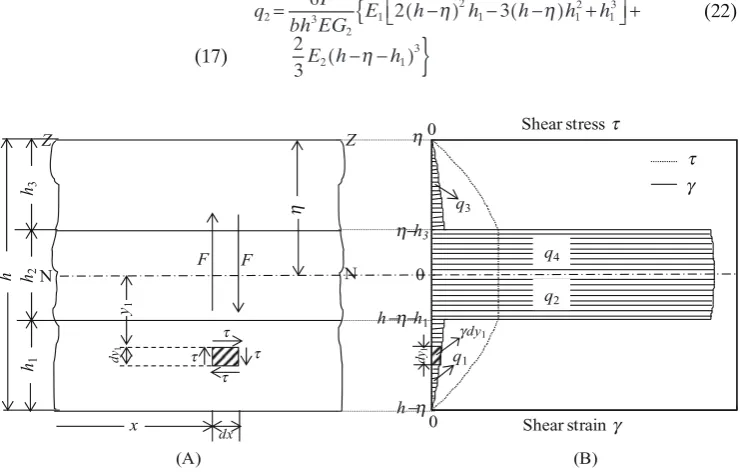
Figure 2 shows schematic diagrams of shear stress and shear strain distribution in longitudinal section of a three-ply laminated material beam. In order to obtain the aver-aged value of shear strain occurring in the section of a three-ply laminated material beam, we determine the inte-gral value of shear strain distribution in its section.
The integral value of shear strain gdy1 for dy1 is obtained as the following equation from Eq. 17.
γdy τ
G dy
1 1
1
= (18)
The integral value of shear strain distribution (q1) from h −h− h1 to h −h of a three-ply laminated material beam shown in Fig. 2 is represented as follows:
q dy
G dy
h h
h
h h
h
1 1
1
1
1 1
1
=
∫
− −−ηη γ =∫
− −−ηη τ (19)where G1 is the shear modulus of the bottom lamina. Substituting shear stress t of Eq. 6 in Eq. 19, we obtain
q FE
bh EG h h
h 1
1 3
1
1
2 1
3 6
3
= ⎡( − ) −
⎣⎢
⎤ ⎦⎥
η (20)
q2 is the integral value of shear strain distribution from 0 to h −h− h1 and is represented as follows:
q y
G dy
h h h h
2 1
0
2
1 0
1 1 1
=
∫
− −η γd =∫
− −η τ (21)where G2 is the shear modulus of the core lamina. Substituting shear stress t of Eq. 10 in Eq. 21, we obtain
q F
bh EG E h h h h h
E h h
2 3
2 1
2
1 1
2 1 3
2 1
3 6
2 3
2 3
=
{
⎡⎣ ( − ) − ( − ) + ⎤⎦ +− −
( )
}
η η
η
(22)
h
x
h1 h2 h3
N
Z Z
h
N
dy1
y1
t t
t t
F F
dx
Shear stress t
(A)
h
h-h3
h-h-h1
h-h
0
dy
1
0
g t
gdy1
q4
q2
q1
q3
0
Shear strain g (B) Fig. 2A, B. Schematic diagrams of shear stress and shear strain in
longitudinal section of three-ply laminated material beam. NN, neutral axis; h, distance from ZZ axis to neutral axis; y1, distance from neutral
axis; F, shear force; t, shear stress; g, shear strain; h, height of three-ply
laminated material beam; h1, h2, and h3, heights of individual laminae;
q1, q2, q3, and q4, integral values of shear strain distribution from h −h − h1 to h −h, from 0 to h −h− h1, from h− h3 to h, and from 0 to h− h3, respectively. B Typical example of shear stress and shear strain
q3 is the integral value of shear strain distribution from
h− h3 to h and is represented as follows:
q dy G dy h h 3 1 3 1 3 3 1
=
∫
ηη− γ =∫
ηη− τ (23)where G3 is the shear modulus of the top lamina. Substituting shear stress t of Eq. 12 in Eq. 23, we obtain
q FE
bh EG h
h 3 3 3 3 3 2 3 3 6 3 = ⎛ − ⎝⎜ ⎞ ⎠⎟
η (24)
q4 is the integral value of shear strain distribution from 0 to h− h3 and is represented as follows:
q dy G dy h h 4 1 0 2 1 0
3 1 3
=
∫
η− γ =∫
η− τ (25)Substituting shear stress t of Eq. 16 in Eq. 25, we obtain
q F
bh EG E h h h
E h 4 3 2 3 2 3 3 2 3
3 2 3
3 6
2 3 2
3
= ⎡
(
− +)
+ ( − )⎣
⎢ η η η ⎤⎦⎥ (26)
q is the total integral value of shear strain distribution from h − h to h and can be expressed as the following equation:
q= + + +q1 q2 q3 q4 (27)
Therefore,
q F
bh E E
G h h
h
E
G h h h h
= ⎡( − ) − ⎣⎢ ⎤ ⎦⎥ ⎧ ⎨ ⎩ + − ( ) − ( − ) 6 3 2 3 3 1 1 1 2 1 3 1 2 2 1 1 2 η η η ++ ⎡⎣ ⎤⎦ + − − ( ) + ⎛ − ⎝⎜ ⎞ ⎠⎟+ − h E
G h h
E G h h E G h 1 3 2 2 1 3 3 3 3 2 3 3 3 2 2 3 2 3 3 2 3 η η
η ηhh h E
G h 3 2 3 3 2 2 3 3 2 3 +
(
)
+ ( − ) ⎫⎬ ⎭ η (28)Because q is the total integral value of shear strain distribution for a height of h, the average strain g¯ is expressed as Eq. 29.
γ η η = = ⎛ ⎝⎜ ⎞⎠⎟ ⎡⎣⎢( − ) − ⎤ ⎦⎥ ⎧ ⎨ ⎩ + ( − ) q h h F bh E E
G h h
h
E
G h h
1 6 3 2 3 1 1 1 2 1 3 1 2 2 1 1 1 2 1 3 2 2 1 3 3 3 3 2 3 3 3 2 3 3 − ( − ) + ⎡⎣ ⎤⎦ + ( − − ) + ⎛ − ⎝⎜ ⎞ ⎠⎟+
h h h E
G h h
E
G h
h E
η η
η 33
2 2 3 3 2 3 3 2 2 3 3
2 3 2
3
G h h h
E
G h
η − η + η
(
)
+ ( − ) ⎫⎬⎭(29)
Because the averaged shear stress is t¯ = F/bh, shear force can be modifi ed as F = bht¯. Therefore, g¯ is derived as Eq. 30.
γ τ η η η = ⎡( − ) − ⎣⎢ ⎤ ⎦⎥ ⎧ ⎨ ⎩ + ( − ) − ( − ) + 6 3 2 3 3 1 1 1 2 1 3 1 2 2 1 1 2 h E E
G h h
h
E
G h h h h hh
E
G h h
E
G h
h E
G h h
1 3 2 2 1 3 3 3 3 2 3 3 3 2 2 3 2 3
3 2 3
⎡⎣ ⎤⎦ + ( − − ) + ⎛ − ⎝⎜ ⎞ ⎠⎟+ − η
η η η 33
2 3 3 2 2 3 3 2 3 +
(
h)
+ E ( − ) ⎫⎬⎭G η h
(30)
Shear modulus
With the shear modulus of a three-ply laminated material beam being represented as G =t¯/g¯, shear modulus G from Eq. 30 is derived as Eq. 31.
G h E
X = 3
6 (31)
where X E
G h h
h E
G h h h h
= ⎡( − ) − ⎣⎢ ⎤ ⎦⎥+ ⎡⎣ ( − ) − ( − ) 1 1 1 2 1 3 1 2 2 1 1 2
3 2 3
η η η
+
]
+ ⋅ ( − − ) + ⋅ ( − ) +(
−+
h E
G h h
E
G h
E
G h h
h 1 3 2 2 1 3 2 2 3 3 3 2 2 3 3 2 3 3 2 3 2
3 2 3
η η η η
))
+E −G h h 3 3 3 2 3 3 3 (η ).
Application of derived equation to calculation of shear
modulus of three-ply cross-laminated wood beam
Specimen preparation
Species used for three-ply laminated wood beams included two softwoods: sugi (Japanese cedar, Cryptomeria japonica D. Don) and hinoki (Japanese cypress, Chamaecyparis obtusa Endl.); and three hardwoods: kiri (royal paulownia, Paulownia tomentosa Steud.), katsura (katsura, Cercidi-phyllum japonicum Sieb. et Zucc.), and buna (beech, Fagus crenata Blume) as described in the previous article.5
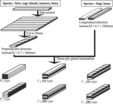
A res-orcinol–phenol resin-type adhesive formulated for a room-temperature cure was used, and the amount of spread was 300 g/m2. Figure 3 shows the three-ply parallel-laminated and cross-laminated wood beam specimens tested.
P|| types are the laminated wood beam specimens with all layers composed of laminae parallel to the grain [P||(KI), P||(SU), P||(HI), P||(KA), P||(BU); KI, kiri; SU, sugi; HI, hinoki; KA, katsura; BU, buna]. P⊥ types are the laminated
wood beam specimens with all layers composed of laminae perpendicular to the grain [P⊥(KI), P⊥(SU), P⊥(HI), P⊥(KA),
P⊥(BU)].
C||(S) type was composed of longitudinal-direction laminae of sugi in the faces and perpendicular-direction lamina of fi ve species in the core [C||(SKI), C||(SSU), C||(SHI), C||(SKA), and C||(SBU)], where prefi x “S” means that the longitudinal-direction laminae in the faces were made of sugi wood. C||(B) type was composed of longitudinal-direction laminae of buna in the faces and perpendicular-direction lamina of fi ve species in the core [C||(BKI), C||(BSU), C||(BHI), C||(BKA), and C||(BBU)], where prefi x “B” means that longitudinal-direction laminae in the faces were made of buna wood. C⊥(S) type was composed of
perpendicular-direction laminae of fi ve species in the faces and longitudinal-direction lamina of sugi in the core [C⊥(SKI), C⊥(SSU), C⊥(SHI), C⊥(SKA), and C⊥ (SBU)],
where the prefi x “S” means that the longitudinal-direction lamina in the core was made of sugi wood. C⊥(B) type
and C⊥(BBU)], where the prefi x “B” means that the
longitudinal-direction lamina in the core was made of buna wood.
P|| types and P⊥ types were the specimens used to measure
the bending strength properties parallel and perpendicular to the grain of parallel-laminated woods, respectively. C|| types and C⊥ types were the specimens used to measure the
bending strengths parallel and perpendicular to the grain of the face laminae of cross-laminated woods, respectively. The number of specimens per type was 3 and total number of specimens was 90.
Bending strength properties test
The static bending test for all laminated wood specimens was conducted by four-point loading. The span was 300 mm, the distance between loading points and supporting points was 100 mm, and the cross head speed was set at 5.0 mm/ min. The defl ection at midspan was measured with a dial gauge, and load–defl ection curves were recorded with an X-Y recorder.
Shear modulus measurement
Static three-point bending test was conducted to obtain shear modulus (G) for parallel-laminated wood beam speci-mens. The relation between the square of the height/span ratio [(h/l)2
] and the compliance (1/Ea) is expressed by the following equation:8
1 1 2
E E
k G
h l
α
= + ( ) (32)
where Ea is the measured MOE, E is the true MOE, G is the shear modulus, k is 6/5 in the case of a rectangular cross section,9
and h and l are the height and span of the specimen.
The span was decreased from 300 mm to 120 mm in decrements of 20 mm, and the MOE corresponding to each span was calculated. The regression line was described from the relation between the square of the height/span ratio and the compliance (1/Ea), and the regression equations were obtained. By applying the regression equation to Eq. 32, shear moduli (G) and true MOE (E) for P|| and P⊥ types
were calculated and the E/G values were obtained.
Species : Kiri, sugi, hinoki, katsura, buna Species : Sugi, buna
Laminated wood specimens(20
¥
20
¥
340mm)
C
||(B)
type
P
||type
C
||(S)
type
C
⊥(S)
type
P
⊥type
C
⊥(B)
type
Longitudinal-direction
lamina(20×6.7×360mm)
Perpendicular-direction
lamina(20×6.7×360mm)
Three-ply glued lamination
Side-jointed
Cut to 20mm
Species : Kiri, sugi, hinoki, katsura, buna Species : Sugi, buna
Longitudinal-direction
lamina(20 6.7 360mm)
Perpendicular-direction
lamina(20 6.7 360mm)
Three-ply glued lamination
Side-jointed
Cut to 20mm
Fig. 3. Parallel-laminated and
cross-laminated wood
Results and discussion
Calculated value of shear modulus
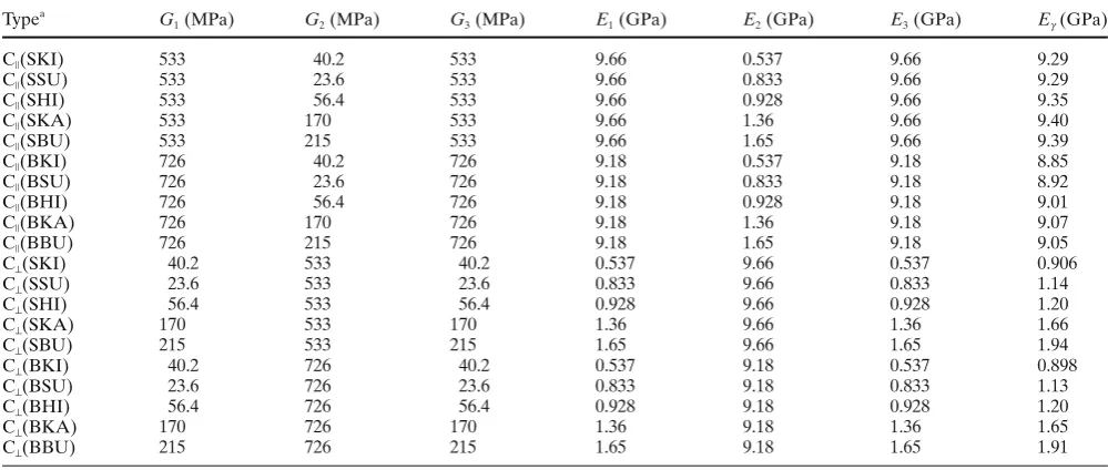
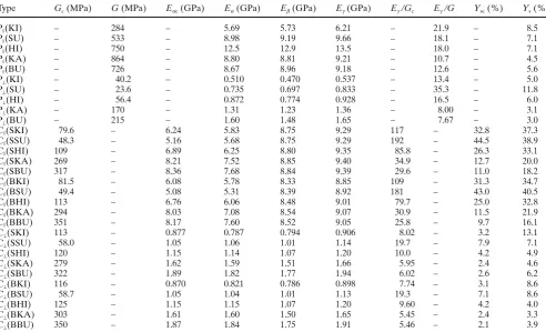
The calculated values of shear moduli of cross-laminated wood beams were obtained using the derived equation for calculating shear modulus of a three-ply laminated material beam. Table 1 shows the shear moduli (G1, G2, and G3) and true MOEs (E1, E2, and E3) of individual laminae and the true MOEs of cross-laminated wood beams that were used for calculating the shear modulus of a cross-laminated wood beam.
The calculated values of shear moduli of cross-laminated wood beams are shown in Table 2. For the C⊥(S) type, the
calculated value of shear modulus for buna [C⊥(SBU)] had
the highest value (322 MPa), whereas that for sugi [C⊥(SSU)]
had the lowest value (58.0 MPa). The values were in the order C⊥(SBU) > C⊥(SKA) > C⊥(SHI) > C⊥(SKI) > C⊥(SSU),
and were in the same order as shear moduli of P⊥ type made
with fi ve species. By replacing the perpendicular-direction lamina of fi ve species in the core of P⊥ type with the
lon-gitudinal-direction lamina of sugi, these values increased to 1.5–2.8 times that for the P⊥ type and the extent of the
increase increased with decreasing density of species. It was found that the calculated values of shear moduli for the C⊥(B) type were slightly higher than those for the
C⊥(S) type.
In contrast, for the C||(S) type, the calculated values of shear modulus for buna [C||(SBU)] had the highest value (317 MPa), whereas that for sugi [C||(SSU)] had the lowest value (48.3 MPa). The values were in the order C||(SBU) >
C||(SKA) > C||(SHI) > C||(SKI) > C||(SSU). By replacing the longitudinal-direction lamina of sugi in the core of the P||(SU) type with the perpendicular-direction lamina of fi ve species, these values decreased to 0.09–0.59 times that for the P||(SU) type and it was found that the extent of the decrease increased with decreasing shear modulus in the cross section of the perpendicular-direction lamina in the core. Also, these values decreased to 0.07–0.48 times that for the P||(BU) type by replacing the longitudinal-direc-tion lamina of buna in the core of the P||(BU) type with the perpendicular-direction lamina of fi ve species.
Apparent defl ection ya of a beam for four-point bending is expressed in the following equation:3
y y y Pl l l
bh E
kPl AG
Pl l l
bh E
α= + =
(
−)
+=
(
−)
+m s
1 2
1 2 3
1
1 2
1 2 3
3 4
4 2
3 4
4 1
2
) ..
. 4
3 4
2 2
1 2 h
l l
E G − ⎡ ⎣⎢
⎤ ⎦⎥
(33)
where ym is the defl ection caused by bending moment; ys is the defl ection caused by shear force; E is the true MOE; G is the shear modulus; P is the applied load; b and h are the width and height of the beam (20 mm, respectively); l is the span (300 mm); l1 is the distance between a loading point and a supporting point (l/3); and k is 6/5 in the case of a rectangular cross section.9
From Eq. 33, the percentage of defl ection caused by shear force is in proportion to E/G. Thus, Eg/Gc values were obtained from the calculated values of shear modulus (Gc) mentioned above and true MOE (Eg) reported in the previ-ous report,5
and are shown in Table 2.
Table 1. Shear moduli and moduli of elasticity of individual laminae, and modulus of elasticity of cross-laminated wood beam, used for
calculation of shear modulus of cross-laminated wood beam
Typea G
1 (MPa) G2 (MPa) G3 (MPa) E1 (GPa) E2 (GPa) E3 (GPa) Eg (GPa)
C||(SKI)
C||(SSU)
C||(SHI)
C||(SKA)
C||(SBU)
533 533 533 533 533
40.2 23.6 56.4 170 215
533 533 533 533 533
9.66 9.66 9.66 9.66 9.66
0.537 0.833 0.928 1.36 1.65
9.66 9.66 9.66 9.66 9.66
9.29 9.29 9.35 9.40 9.39 C||(BKI)
C||(BSU)
C||(BHI)
C||(BKA)
C||(BBU)
726 726 726 726 726
40.2 23.6 56.4 170 215
726 726 726 726 726
9.18 9.18 9.18 9.18 9.18
0.537 0.833 0.928 1.36 1.65
9.18 9.18 9.18 9.18 9.18
8.85 8.92 9.01 9.07 9.05 C⊥(SKI)
C⊥(SSU)
C⊥(SHI)
C⊥(SKA)
C⊥(SBU)
40.2 23.6 56.4 170 215
533 533 533 533 533
40.2 23.6 56.4 170 215
0.537 0.833 0.928 1.36 1.65
9.66 9.66 9.66 9.66 9.66
0.537 0.833 0.928 1.36 1.65
0.906 1.14 1.20 1.66 1.94 C⊥(BKI)
C⊥(BSU)
C⊥(BHI)
C⊥(BKA)
C⊥(BBU)
40.2 23.6 56.4 170 215
726 726 726 726 726
40.2 23.6 56.4 170 215
0.537 0.833 0.928 1.36 1.65
9.18 9.18 9.18 9.18 9.18
0.537 0.833 0.928 1.36 1.65
0.898 1.13 1.20 1.65 1.91
Each value is the average of three measurements and is also shown in Table 2. h1= h2= h3= 6.7 mm
G1, G2, and G3, shear moduli of bottom, core, and top laminae; E1, E2, and E3, true modulus of elasticity (MOE) values of bottom, core, and
top laminae; Eg, true MOE of cross-laminated wood
a Prefi x S, sugi; prefi x B, buna used as longitudinal-direction laminae of cross-laminated woods
The true MOE (Eg) of cross-laminated wood beam was obtained as follows. The true MOE (Eg) of parallel-laminated wood beam was calculated using E = Ea (1 +j) [j = 2.4h2
/(3l2 − 4l1
2
)·(E/G) = 0.00417·(E/G)] from Ea and E/G. E/G was obtained by the method described for shear modulus measurement. The apparent MOEs of individual laminae were measured, and the true MOEs of individual laminae were calculated from Ea and E/G. The true MOE (Eb) of parallel-laminated wood beams without the contribution of the glue line was calculated from the true MOEs of the individual laminae by the equiv-alent cross-section method. Furthermore, the relation between the ratio of the true MOE (Eg) having the contri-bution of glue line to Eb (Rg= Eg/Eb) and 1/Eb of parallel-laminated wood beams was represented by the following equation:
Rg=0 068 1. ⋅( Eβ)+1 054. (r=0 742. ,significant at 1% level) Eb of cross-laminated wood beams was calculated from the true MOEs of individual laminae using the equivalent cross-section method. Assuming that this regression equation of parallel-laminated wood beam was also valid for cross-laminated wood beam, then Rg of cross-laminated wood beam was obtained from Eb by the regression equation and
Eg was obtained from Rg and Eb.
For C⊥(S) type, the Eg/Gc values were in the order C⊥(SSU) > C⊥(SHI) > C⊥(SKI) > C⊥(SBU) > C⊥(SKA), and
the values had low values of 5.95–19.7, and its difference among species of laminae used in the faces was found to be small. By replacing the perpendicular-direction lamina of fi ve species in the core of P⊥ type with the
longitudinal-direction lamina of sugi, Eg and Gc increased to 1.2–1.7 times and 1.5–2.8 times those for the P⊥ type, respectively,
and Eg/Gc decreased to 0.56–0.78 times that for the P⊥ type.
A similar result was found for C⊥(B) type.
In contrast, for the C||(S) type, the Eg/Gc values were in the order C||(SSU) > C||(SKI) > C||(SHI) > C||(SKA) > C||(SBU). Sugi [C||(SSU)] had the highest value (192), whereas buna [C||(SBU)] had the lowest value (29.6). There was a marked difference in the value among species of laminae used in the core. By replacing the longitudinal-direction lamina of sugi in the core of P||(SU) type with the perpendicular-direction lamina of fi ve species, Eg/Gc increased by 1.6 (buna) to 11 times (sugi). The reason is that Eg values decreased only to 0.96–0.97, whereas Gc decreased to 0.09 (sugi) to 0.59 (buna). It was found that there was a large difference in Eg/Gc among species used for the core lamina. Eg/Gc values were in the order C||(SSU) > C||(SKI)
> C||(SHI) > C||(SKA) > C||(SBU). A similar result was found for C||(B) type.
Table 2. Shear modulus calculated by using derived equation (Gc), apparent modulus of elasticity calculated from Gc (Eac), Eg /Gc, and
percent-age of calculated defl ection caused by shear force (Ysc) of cross-laminated wood beams
Type Gc (MPa) G (MPa) Eac (GPa) Ea (GPa) Eb (GPa) Eg (GPa) Eg /Gc Eg /G Ysc (%) Ys (%)
P||(KI)
P||(SU)
P||(HI)
P||(KA)
P||(BU)
– – – – – 284 533 750 864 726 – – – – – 5.69 8.98 12.5 8.80 8.67 5.73 9.19 12.9 8.81 8.96 6.21 9.66 13.5 9.21 9.18 – – – – – 21.9 18.1 18.0 10.7 12.6 – – – – – 8.5 7.1 7.1 4.5 5.6 P⊥(KI)
P⊥(SU)
P⊥(HI)
P⊥(KA)
P⊥(BU)
– – – – – 40.2 23.6 56.4 170 215 – – – – – 0.510 0.735 0.872 1.31 1.60 0.470 0.697 0.774 1.23 1.48 0.537 0.833 0.928 1.36 1.65 – – – – – 13.4 35.3 16.5 8.00 7.67 – – – – – 5.0 11.8 6.0 3.1 3.0 C||(SKI)
C||(SSU)
C||(SHI)
C||(SKA)
C||(SBU)
79.6 48.3 109 269 317 – – – – – 6.24 5.16 6.89 8.21 8.36 5.83 5.68 6.25 7.52 7.68 8.75 8.75 8.80 8.85 8.84 9.29 9.29 9.35 9.40 9.39 117 192 85.8 34.9 29.6 – – – – – 32.8 44.5 26.3 12.7 11.0 37.3 38.9 33.1 20.0 18.2 C||(BKI)
C||(BSU)
C||(BHI)
C||(BKA)
C||(BBU)
81.5 49.4 113 294 351 – – – – – 6.08 5.08 6.76 8.03 8.17 5.78 5.31 6.06 7.08 7.60 8.33 8.39 8.48 8.54 8.52 8.85 8.92 9.01 9.07 9.05 109 181 79.7 30.9 25.8 – – – – – 31.3 43.0 25.0 11.5 9.7 34.7 40.5 32.8 21.9 16.1 C⊥(SKI)
C⊥(SSU)
C⊥(SHI)
C⊥(SKA)
C⊥(SBU)
113 58.0 120 279 322 – – – – – 0.877 1.05 1.15 1.62 1.89 0.787 1.06 1.14 1.59 1.82 0.794 1.01 1.07 1.51 1.77 0.906 1.14 1.20 1.66 1.94 8.02 19.7 10.0 5.95 6.02 – – – – – 3.2 7.9 4.2 2.4 2.6 13.1 7.1 4.9 4.6 6.2 C⊥(BKI)
C⊥(BSU)
C⊥(BHI)
C⊥(BKA)
C⊥(BBU)
116 58.7 125 303 350 – – – – – 0.870 1.05 1.15 1.61 1.87 0.821 1.04 1.15 1.60 1.84 0.786 1.01 1.07 1.50 1.75 0.898 1.13 1.20 1.65 1.91 7.74 19.3 9.60 5.45 5.46 – – – – – 3.1 7.1 4.2 2.4 2.1 8.6 8.6 4.0 3.3 3.9
Each value of G, Ea, Eb, and Eg is the average value of three measurements. G, Ea, Eb, and Eg were reported previously by Park et al.5
G, Shear modulus of parallel-laminated wood beam; Ea, measured apparent MOE; Eb, MOE calculated from true MOE values of individual
laminae using equivalent cross-section method; Eg, true MOE of laminated wood beam; Ys, percentage of measured defl ection caused by shear
Relation between calculated value and measured value of apparent MOE
The calculated apparent MOE (Eac) of cross-laminated wood beam is derived as the following equation from Eq. 33.
Eαc=Eγ (1+ϕ) (34)
where Eg is the true MOE, j= 2.4h
2 /(3l2−
4l1 2
)·(Eg/Gc) = 0.00417·(Eg/Gc).
Figure 4 shows the percentage of difference between the measured value and the calculated value versus the measured value of apparent MOE of cross-laminated wood beam related to its Gc. For the C⊥ type, its difference was
in the range of 0.9% to −11%, and the calculated value was in fair agreement with the measured value.
On the other hand, for the C|| type, the calculated values of C||(SSU) and C||(BSU), with core composed of perpendicular-direction lamina of sugi with the lowest shear modulus of fi ve species, were 9.2% and 4.3% smaller than the measured values, respectively. Conversely, for the other C|| types, the calculated values were 5.2% to 14% greater than the measured values. The range of the difference between both values was slightly wider in C|| type than in C⊥ type, but good agreement between both values was also
found. From the above results, it was found that the calculated value of cross-laminated wood beams was able to be obtained from the MOEs and shear moduli of laminae.
Percentage of defl ection caused by shear force
The percentage of defl ection caused by shear force versus total defl ection can be obtained by the following equation from the true MOE and the measured apparent MOE as mentioned in the previous report.5
Y y y
y
E E
E s
m
= α− × = − × ( )
α
γ α γ
100 100 % (35)
Also, the percentage of defl ection caused by shear force versus total defl ection of cross-laminated wood beams can be obtained by the following equation from the true MOE and the calculated apparent MOE.
Y y y
y
E E
E sc
c m
c
c
= α − × = − × ( )
α
γ α γ
100 100 % (36)
Table 2 shows the Ys values that were reported in our previous article5
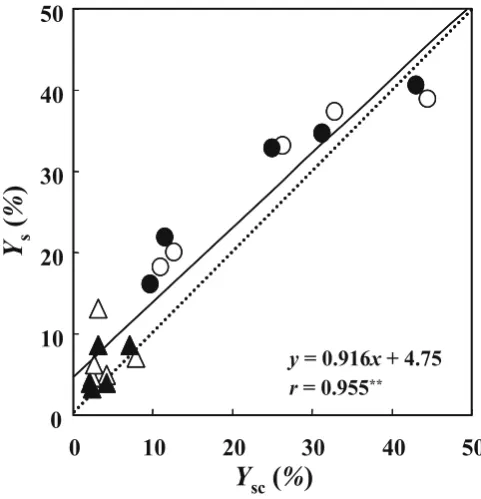
and Ysc values, and the comparison of these values is shown in Fig. 5.
For the C⊥(S) type, the Ysc value, which is the calculated value of the percentage of defl ection caused by shear force, was in the range of 2.4%–7.9%, and the values were slightly lower than Ys values of 4.6%–13.1% calculated from the measured values in the previous study.5 However, their differences were small. A similar result was found for C⊥(B)
type with the core composed of longitudinal-direction lamina of buna.
On the other hand, for the C||(S) type, the Ysc of C||(SSU) with the core composed of perpendicular-direction lamina of sugi had the highest value of 44.5%, and that of C||(SBU) with the core composed of perpendicular-direction lamina of buna had the lowest value of 11.0%. The Ysc value was in the order C||(SSU) > C||(SKI) > C||(SHI) > C||(SKA) > C||(SBU), and it had the same order as the Ys described in the previous article.5
A similar result was found for C||(B) type.
Figure 5 shows the regression line for the relation between Ysc and Ys by the least-squares method and a very high correlation (r = 0.955, signifi cant at 1% level) was obtained. In this fi gure, the straight line of y = x is shown by the dotted line to examine if Ysc agreed with Ys. C⊥(SKI) and C⊥(BKI) with faces composed of
perpendicular-(E
a
–
E
ac
) /
E
a¥
100
(%
)
-20 -10 0 10 20
0 100 200 300 400
G
c(MPa)
C^type
G
c(MPa)
C type
-20 -10 0 10 20
0 100 200 300 400
E
400
||
400
Fig. 4. Percentage of difference between measured value and calculated
value versus measured value of apparent modulus of elasticity (MOE) of cross-laminated wood beam related to its Gc. Ea, measured apparent
MOE; Eac, calculated apparent MOE. Open circles, SSU; fi lled circles,
BSU; open squares, SKI; fi lled squares, BKI; open triangles, SHI; fi lled
triangles, BHI; open diamonds, SKA; fi lled diamonds, BKA; open inverted triangles, SBU; fi lled inverted triangles, BBU. Prefi x S, sugi;
direction lamina of kiri were situated somewhat above the line, whereas C||(SSU) and C||(BSU) with cores composed of perpendicular-direction lamina of sugi were situated a little below it. On the whole, the Ys values were higher than the Ysc values, but their values were near the line. From the above results, it is considered that the validity of the derived equation for calculating shear modulus was verifi ed.
Conclusions
In this study, we derived an equation for calculating the shear modulus of a three-ply laminated material beam from shear moduli of individual laminae. The validity of the derived equation was investigated using cross-laminated wood beams made with fi ve species reported in our previ-ous article.5
The key fi ndings of the study are:
Y
s(
%
)
Y
sc(
%
)
y
= 0.916
x
+ 4.75
r
= 0.955
**0
10
20
30
40
50
0
10
20
30
40
50
Fig. 5. Comparison of Ys value with Ysc value of cross-laminated wood
beam. Ys, percentage of defl ection caused by shear force and calculated
from measured apparent MOE and true MOE; Ysc, percentage of
defl ection caused by shear force and calculated from calculated appar-ent MOE and true MOE. Dotted line, y = x; open circles, C||(S) type; fi lled circles, C||(B) type; open triangles, C⊥(S) type; fi lled triangles,
C⊥(B) type; double asterisk, signifi cant at 1% level
1. The calculated shear moduli of cross-laminated wood beams increased markedly with increasing shear modulus in cross section for perpendicular-direction laminae of both core and faces.
2. The calculated value and the measured value of apparent MOE of cross-laminated wood beam were in good agreement, and it was found that the apparent MOE was able to be calculated from the true MOEs and shear moduli of laminae.
3. For a cross-laminated wood beam with perpendicular-direction laminae in the faces, the calculated value and the measured value of the percentage of defl ection caused by shear force were small. For beams with longitudinal-direction laminae in the faces, these same values increased markedly with decreasing shear modulus in cross section of core lamina. The Ys values were close to the Ysc values and there was a very high correlation between them.
From the above results, the high validity of the derived equation for calculating shear modulus of cross-laminated wood beams was apparent.
References
1. Japanese Agricultural Standards (2007) Glued laminated wood. Bending test. Japanese Agricultural Standards Association, Tokyo, pp 55–57
2. Japanese Agricultural Standards (2008) Laminated veneer lumber. Bending test. Japanese Agricultural Standards Association, Tokyo, pp 21–22
3. Park HM, Fushitani M, Ohtsuka T, Nakajima T, Sato K, Byeon HS (2001) Effect of annual ring angle on static bending strength per-formances of cross-laminated woods made with sugi wood (in Japanese). Mokuzai Gakkaishi 47:22–32
4. Park HM, Fushitani M (2006) Effects of component ratio of the face and core laminae on static bending strength performance of three-ply cross-laminated wood panels made with sugi. Wood Fiber Sci 38:278–291
5. Park HM, Fushitani M, Sato K, Kubo T, Byeon HS (2003) Static bending strength performances of cross-laminated woods made with fi ve species. J Wood Sci 49:411–417
6. Park HM, Fushitani M, Sato K, Kubo T (2004) Static bending strength performances of wood-aluminum hybrid laminated material. Trans Mater Res Soc Jpn 29:2503–2506
7. Utokuchi T, Kawada Y, Kuranishi M (1998) Strength of materials (in Japanese). Shokabo, Tokyo, pp 268–272
8. Yoshihara H, Kubojima Y (2002) Measurement of shear modulus of wood by asymmetric four-point bending tests. J Wood Sci 48: 14–19