LETTER
LIDAR system with electromagnetic two-axis
scanning micromirror based on indirect
time-of-flight method
Seung‑Han Chung, Sung‑Woo Lee, Seung‑Ki Lee and Jae‑Hyoung Park
*Abstract
This paper presents a light detection and ranging (LIDAR) system using electromagnetically actuated two‑axis scan‑ ning micromirror. The distance measurement with the LIDAR is based on the indirect time‑of‑flight method using the relative ratio of the accumulated charges in capacitors connected to photodiode pixels, which is determined by the time difference between the transmitted and reflected light pulse. The micromirror has double gimbaled structure for two‑axis actuation and circular reflection plate with the diameter of 3 mm. The horizontal scan angle of 49.13° was obtained by the resonant actuation at 28 kHz, and the vertical scan of 29.23° was achieved by the sinusoidal forced actuation at 60 Hz. The distance to multiple targets could be measured at once by laser scanning using the micromir‑ ror, and the distance profile LIDAR image was constructed by the measurement results.
Keywords: LIDAR system, Micromirror, Indirect time‑of‑flight method, Distance measurement
© The Author(s) 2019. This article is distributed under the terms of the Creative Commons Attribution 4.0 International License (http://creat iveco mmons .org/licen ses/by/4.0/), which permits unrestricted use, distribution, and reproduction in any medium, provided you give appropriate credit to the original author(s) and the source, provide a link to the Creative Commons license, and indicate if changes were made.
Introduction
The LIDAR system has been one of the important research topics in the remote sensing technologies for three-dimensional imaging based on the distance meas-urement and diverse environmental monitoring. LIDAR has been studied intensively to be applied to the vari-ous applications such as autonomvari-ous vehicles, obstacle detection and security [1–5]. In the conventional LIDAR system, a motorized laser scanning unit such as galva-nometer scanner is widely used for the detection of large area. In addition, LIDAR system has the disadvantages of having a large and heavy units with high cost. Recently, many research activities have been directed toward the development of LIDAR system using the micromirror, which has small size, light weight and low power con-sumption [6, 7].
In the LIDAR systems, the phase shift and time-of-flight method have been applied for the distance measurement. Laser beam is emitted to the target and reflected through receiving lens. In the phase shift method, the intensity
modulated beam at a particular frequency is emitted to the target, and phase shift is produced in the reflected light depending on the distance to target [2, 8]. Even with the precise measurement of distance, however, the phase shift method requires a complicated system includ-ing laser beam modulation and data processinclud-ing system. In addition, the phase shift method has disadvantage to be applied to real-time measurement because long pro-cessing time is required for precise distance ranging [1,
9]. Time-of-flight method calculates the distance using time difference between transmitted and reflected light beam [10]. Time-of-flight method enables a simple sys-tem setup and distance calculation, but can make rela-tively large measurement error compared with the phase shift method [9]. The indirect time-of-flight calculates the distance to a target by measuring the phase difference between the emitted and the reflected pulse. Since the relative ratio of the phase difference determined by two pulse signals is used for the measurement of distance, the high-precision time measurement sensor is not required for the indirect time-of-flight method [11–14].
In this paper, we present the LIDAR system using elec-tromagnetically actuated two-axis scanning micromirror based on the indirect time-of-flight method. The indirect
Open Access
*Correspondence: [email protected]
time-of-flight method uses the relative ratio of the accu-mulated charges in capacitors connected to image sen-sor pixels, which is determined by the time difference between transmitted and reflected light beam. The dis-tance measurement and imaging was demonstrated using the two-dimensional laser scanning with micromirror. Since the micromirror has a high scanning speed with small volume, it can make the system more compact and simple with high measurement rate compared to the sys-tem using conventional motor-based laser scanning units [6, 15, 16].
Design and experimental setup
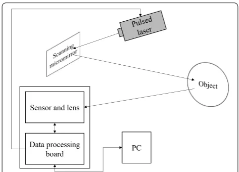
Figure 1 shows the schematic diagram of the LIDAR sys-tem using two-axis scanning micromirror for distance measurement. The LIDAR system is composed of a pulsed laser (Toptica laser beam, 640 nm, 150 mW), scan-ning micromirror, receiving lens (TF 8 M, 8 mm focal length, 1/3 inch), image sensor made of avalanche photo-diode (Hamamatsu, S11963-01CR, 160 × 120 pixels), and data processing board. Figure 2 shows the LIDAR system setup on the optical table. The pulsed laser is transmitted and reflected at the two-axis scanning micromirror, and emitted to the targets. The laser is scanned to the objects through the micromirror. The beam scattered from the object enters the receiving lens and detected at the sen-sor. The data processing board converts the collected light information into the distance and image informa-tion. In the LIDAR system, the laser diode having 640 nm wavelength and 150 mW average power was used as light emitting source with the adjustable pulse duration from 3 ns to continuous wave. The image sensor with
160 × 120 pixels photodiode array and receiving lens with the field of view of 37.5° × 27.7° were used.
Figure 3 shows the basic circuit structure at the pho-tosensitive area of the photodiode to obtain the distance with indirect time-of-flight method. The distance meas-urement is using the relative ratio of the accumulated charges in each capacitor connected to photodiode output. The pulse timing chart at the circuit is shown in Fig. 4. The transmitted and reflected light pulses are shown. T0 is transmitted light pulse width, and Td is time difference between transmitted and reflected light pulse, which is dependent on the distance from source to tar-get. The pulses to turn on the switch 1 and 2 are also shown, which are connected to the capacitor 1 (C1) and 2 (C2), respectively. The switch 1 turn-on pulse is syn-chronously generated with the transmitted light pulse, and then the switch 2 pulse is generated at the end of switch 1 pulse. Therefore, Q1 represents the amount of
charge accumulated in C1 during the switch 1 turn-on period, which is generated at the photodiode due to the reflected light pulse. Q2 is the accumulated charge in C2 from the reflected light pulse. The ratio of the charge is determined by the time difference between the transmit-ted and reflectransmit-ted light pulse. Therefore, the distance D is calculated by Eq. (1);
where c is light velocity, T0 is transmitted light pulse width, Q1 and Q2 are charges accumulated in C1 and C2, respectively. The switch 3 is to discharge unneeded charges caused by ambient light during the non-emis-sion period. In the experiment, the switch 3 turn-on pulse width was set to 40 ns. The image sensor signals from reflected light and charge-to-voltage conversion
(1) D=
1
2×c×T0×
Q2
Q1+Q2
Sensor and lens
Data processing
board PC
Fig. 1 Schematic diagram of the LIDAR system using two‑axis scanning micromirror
on accumulated charges are processed to calculate dis-tance through the data processing board (S11963-01CR, Hamamatsu) [17]. In the LIDAR system, the transmitted light pulse width (T0) was set to 90 ns, which means the measureable distance to an object is 13.5 m.
Electromagnetic two‑axis scanning micromirror
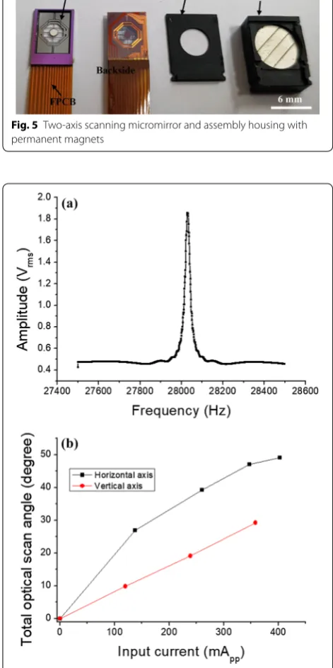
The electromagnetically actuated two-axis scanning micromirror was employed in the LIDAR system, which was developed in our previous study [18]. The scanning micromirror used in the LIDAR system is shown in Fig. 5. The micromirror device consists of a microfabricated double gimbaled structure and a set of permanent mag-nets for high magnetic field generation. A current path using electroplated copper coil is formed on the backside to generate torque under magnetic field. The size of the circular mirror plate is 3 mm in diameter, on which an aluminum reflective surface is formed. The fast horizon-tal scan is obtained by the resonant mode actuation, while the tilting for slow vertical scan is achieved by forced actuation. The micromirror is assembled with permanent
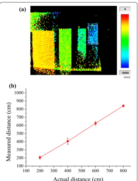
magnets using plastic housing, and the volume of the packaged device is 6.6 mm × 11 mm × 4.72 mm. For hori-zontal scan, maximum optical scan angle of 49.13° at the resonance frequency of 28.0 kHz was obtained. The verti-cal scan angle was 29.23° at 60 Hz as shown in Fig. 6.
Switch 3 Charge drain
Switch 1
Distance image sensor
C1 C2
Switch 2
Fig. 3 Indirect time‑of‑flight circuit structure at the photosensitive area of the photodiode
Fig. 4 Pulse timing chart for the distance measurement of indirect time‑of‑flight method
Fig. 5 Two‑axis scanning micromirror and assembly housing with permanent magnets
LIDAR image and distance measurements
Figure 7a shows target object setup to test the distance measurement using the LIDAR system. White panels were used for the targets, which are placed at 200, 400, 600, and 800 cm from the laser. The laser scan image to the targets using the two-axis scanning micromirror is shown in Fig. 7b. All the targets are in the field of view of micromirror optical scan angle, and the distance to multiple targets were measured at the same time with the laser scan. The experiment was performed in the dark environment, where the ambient light was blocked.
Figure 8a shows the distance profile image in the scanned area, which is constructed by the distance meas-urement results at each pixel of photodiode image sensor. At each pixel, the distance was obtained by the average value of calculation using the charge ratio of Q1 and Q2 at a frame rate of 100/s. In addition, the distance values of 15 × 15 pixels were taken at the center of each target panel and averaged to determine the measured distance to each target. Figure 8b shows the comparison of the measured distance with the actual distance to each tar-get. The measurement distances are the average values for 100 frame. For 200, 400, 600, and 800 cm targets, the distance was measured to be 204.8 ± 17.8, 404.7 ± 37.6, 625.4 ± 23.8, and 840.6 ± 12.1 cm, respectively. The measurement errors tend to increase as increas-ing the distance. The distance resolution of the system is obtained to be about 36 cm using 3 standard deviation rule, which is the general method to calculate the limit of detection. It is considered that the main factor related to
Fig. 7 a Target object setup to test the distance measurement using the LIDAR system, b laser scan image to the targets using two‑axis scanning micromirror
100 200 300 400 500 600 700 800 100
200 300 400 500 600 700 800 900 1000
)
mc(
ec
nat
sid
der
usa
e
M
Actual distance (cm)
(a)
(b)
(mm)
distance resolution is synchronization of the pulsed laser with the control signal. Laser diode is controlled and syn-chronized by the pulse signal from the processing board. The control signal pulse width was set to 90 ns, but the laser pulse synchronization error was about 2 ns. The results show that two-axis scanning micromirror could be applied for the LIDAR system based on the indirect time-of-flight method with the distance measurement.
Conclusion
In this paper, the feasibility of the LIDAR system using electromagnetic two-axis scanning micromirror has been successfully demonstrated based on indirect time-of-flight method. By using the transmitted laser scan with the micromirror and the ratio of the accumulated charges in capacitors determined by the reflected light, the distance to multiple targets could be measured at the same time, and the distance profile LIDAR image could be obtained. The distance measurement results show that the scanning micromirror can be readily applied to the indirect time-of-flight LIDAR system. The proposed LIDAR system is expected to be used in various applica-tion areas with further improvement of the LIDAR optics combined with the scanning micromirror.
Authors’ contributions
JHP devised the idea and supervised the project. JHP, SHC, SWL, and SKL dis‑ cussed the design and experimental setup. SHC performed the LIDAR experi‑ ment using the scanning micromirror. JHP and SHC drafted the manuscript. All authors read and approved the final manuscript.
Acknowledgements
Not applicable.
Competing interests
The authors declare that they have no competing interests.
Availability of data and materials
Not applicable.
Funding
This research was supported by the Space Core Technology Development Program through the National Research Foundation of Korea (NRF) funded by the Ministry of Science and ICT (NRF‑2013M1A3A3A02042410).
Publisher’s Note
Springer Nature remains neutral with regard to jurisdictional claims in pub‑ lished maps and institutional affiliations.
Received: 12 December 2018 Accepted: 8 March 2019
References
1. Hu P, Tan J, Yang H, Zhao X, Liu S (2011) Phase‑shift laser range finder based on high speed and high precision phase‑measuring techniques.
In: Proceedings of the 10th international symposium of measurement technology and intelligent instrument, Daejeon, 1–5 July 2011 2. Lefsky MA, Cohen WB, Parker GG, Harding DJ (2002) Lidar remote sensing
for ecosystem studies: Lidar, an emerging remote sensing technol‑ ogy that directly measures the three dimensional distribution of plant conopies, can accurately estimate vegetation structural attributes and should be of particular interest to forest, landscape, and global ecologists. Bioscience 52:19–30
3. Asvadi A, Premebida C, Peixoto P, Nunes U (2016) 3D Lidar‑based static and moving obstacle detection in driving environments: an approach based on voxels and multi‑region ground planes. Rob Auton Syst 83:299–311
4. Gietelink O, Ploeg J, Schutter BD, Verhaegen M (2006) Development of advanced driver assistance systems with vehicle hardware‑in‑the‑loop simulations. Vehicle Syst Dyn 44:569–590
5. Takai I, Matsubara H, Soga M, Ohta M, Ogawa M, Yamashita T (2016) Single‑photon avalanche diode with enhanced NIR‑sensitivity for auto‑ motive LIDAR Systems. Sensors 16:459–467
6. Niclass C, Ito K, Soga M, Matsubara H, Aoyagi I, Kato S, Kagami M (2012) Design and characterization of a 256x64‑pixel single‑photon imager in CMOS for a MEMS‑based laser scanning time‑of‑flight sensor. Opt Express 20:11863–11881
7. Brigante CMN, Abbate N, Basile A, Faulisi AC, Sessa S (2011) Towards miniaturization of a MEMS‑based wearable motion capture system. IEEE Trans Ind Electron 58:3234–3241
8. Bamji CS, O’Connor P, Elkhatib T, Mehta S, Thompson B, Prather LA, Snow D, Akkaya OC, Daniel A, Payne AD, Perry T, Fenton M, Chan VH (2015) A 0.13 μm CMOS system‑on‑chip for a 512 × 424 time‑of‑flight image sen‑ sor with multi‑frequency photo‑demodulation up to 130 MHz and 2 GS/s ADC. IEEE J Solid‑State Circuits 50:303–319
9. Amann M‑C, Bosch TM, Lescure M, Myllylae RA, Rioux M (2001) Laser ranging: a critical review of unusual techniques for distance measure‑ ment. Opt Eng 40:10–19
10. Gokturk SB, Yalcin H, Bamji C (2004) A time‑of‑flight depth sensor—sys‑ tem description, issues and solutions. In: Proceedings of the 4th IEEE Computer vision and pattern recognition workshop, Washington DC, 35–43 May 2006
11. Perenzoni M, Stoppa D (2011) Figures of merit for indirect time‑of‑flight 3D cameras: definition and experimental evaluation. Remote Sens 3:2461–2472
12. Bellisai S, Villa F, Tisa S, Bronzi D (2012) Indirect time‑of‑flight 3D ranging based on SPADs. In: Proceedings of quantum sensing and nanophotonics devices IX, California, Jan 2012
13. Jang J, Hwang S, Park K (2013) Design of indirect time‑of‑flight based lidar for precise three‑dimensional measurement under various reflection conditions. In: Proceedings of the 4th international conference on sensor device technologies and applications, Barcelona, 25–29 Aug 2013 14. Yasutomi K, Usui T, Han S‑M, Takasawa T, Kagawa K, Kawahito S (2014) An
indirect time‑of‑flight measurement technique with impulse photocur‑ rent response for sub‑millimeter range resolved imaging. Opt Express 22:18904–18913
15. Kasturi A, Milanovic V, Atwood BH, Yang J (2016) UAV‑borne lidar with MEMS mirror‑based scanning capability. In: Proceedings of the laser radar technology and applications XXI, Maryland, May 2016
16. Hu Q, Pedersen C, Rodrigo PJ (2016) Eye‑safe diode laser doppler lidar with a MEMS beam‑scanner. Opt Express 24:1934–1942
17. http://www.hamam atsu.com/us/en/produ ct/categ ory/3100/4005/4148/ S1196 3‑01CR/index .html. Accessed 02 Feb 2018