RESEARCH
Seismic Performance of Special Structural
Walls Using Overlapping Hoops Instead
of Closed Hoops
Jin‑Kyu Song
1, Young‑Soo Chun
2, Jeong‑Weon Song
1, Keun‑Hyeok Yang
3and Kug‑Kwan Chang
1*Abstract
In this study repeated cyclic loading tests were carried out on seven shear wall specimens, which were fabricated in a real scale. The purpose of these experiments is to investigate the difference on the seismic performance of the wall depending on two methods of confining longitudinal bars at the wall boundaries and propose relaxed bar arrangement details that could be used in a moderate to high seismicity zone. The results showed that the seismic performance of special shear walls using overlapping loops as transverse reinforcement of the boundary element was similar to that of special shear walls using a closed hoop in strength, stiffness, and energy dissipation. This means the former can serve as an alternative for rational seismic design for moderate to high seismicity zones using overlapping hoops.
Keywords: special structural wall, cyclic loading test, seismic performance, flexural failure, performance based design
© The Author(s) 2019. This article is distributed under the terms of the Creative Commons Attribution 4.0 International License (http://creat iveco mmons .org/licen ses/by/4.0/), which permits unrestricted use, distribution, and reproduction in any medium, provided you give appropriate credit to the original author(s) and the source, provide a link to the Creative Commons license, and indicate if changes were made.
1 Introduction
When a structure is rattled by an earthquake, each structural member of the structure absorbs the energy through inelastic deformation. This deteriorates perfor-mance such as the structure’s resisting force, stiffness, and strength and impairs the structure as a whole (Korea Concrete Institute 2015; Song 2017). The reinforced con-crete shear wall, which is used as the main lateral force resistance element of reinforced concrete high-rise struc-tures, is subjected to vertical loads such as dead load and live load and lateral load due to earthquakes. At this time, when both ends of the shear wall are not designed in appropriately confined bar arrangement details, plastic hinges do not see smooth distribution because of behav-ioral characteristics so that a highly brittle form of frac-ture mode is observed in which abrupt fracfrac-ture occurs due to crushing only of the bottom part of the compres-sion side. Such brittle fracture leads to eroded stability of
the whole structure, providing a major cause for collapse. To reduce such risks, many countries have design codes that include design specifications to secure a given level of ductility up to fracture point after the wall reaches its maximum strength; this is done by reinforcing the wall end in the plastic hinge (ACI Committee 318 2014; Brit-ish Standards Institution 2004; Architectural Institute of Japan 2010; Architectural Institute of Korea 2016). For example, Special shear walls as defined in ACI318 (ACI Committee 318 2014) and KBC 2016 (Architec-tural Institute of Korea 2016) the ductile wall as defined in EN.1998.1;2004 (British Standards Institution 2004), and the RC wall with boundary columns of AIJ stand-ard (Architectural Institute of Japan 2010) belong to this category. The commonality of these walls is that a given section of both ends of the walls is made to confine the main reinforcement by bar arrangement of laterally con-fined steel reinforcement as if columns were installed (see Table 1).
As demand for ultra-high-rise buildings has recently gone up, the number of buildings requiring application of the special shear wall system has also risen. Problems in construction, however, are being caused by the lateral rein-forcement details of the special boundary element. Though
Open Access
*Correspondence: [email protected]
1 School of Architecture, Chonnam National University, Gwangju 61186,
Republic of Korea
such details of columns using closed stirrup is applied to the same details of the special boundary element in the code, many problems occur in construction (Chun et al. 2013). This is because steel reinforcement is too dense at the end as lateral reinforcement bars are arranged for the wall together with horizontal steel reinforcement in a small cross section compared with columns.
A tendency also exists for excessive design in the standard for seismic design when the standard for high seismicity zones (ACI318-14) is applied like the seismic design standard of moderate to high seismicity zones. So the development of requirement details is needed for a special shear wall system considering moderate to high seismicity characteristics. Therefore, Architectural Insti-tute of Korea (2011, 2013) analyzed problems resulting from hands-on application in relation to boundary ele-ment regulations of special shear walls and conducted a study to present guidelines for rational application of design code (Chun et al. 2011).
In the present study, based on previous research results, the seismic performance of the special shear walls with application of an overlapping hoop will be compared and reviewed to verify validity and present the data for rational seismic design of moderate to high seis-micity zones.
2 Experimental Program
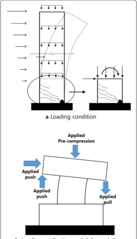
The present study conducted cyclic loading tests for seven shear walls of the flexural failure type, including a shear wall without special boundary element. As the per-formance of the overall system is determined by that of the wall’s lower part in the case of a high-rise shear wall governed by flexure, the experimental specimens were produced for the wall only of the 1 bottommost floor as shown in Fig. 1 by considering the circumstances of a laboratory.
Table 1 Special provisions for shear walls with boundary elements.
Ach: cross-sectional area of a member measured to the outside edges of transverse reinforcement; Ag: gross area of concrete section; b: width of confined parts of
a wall section; b0: width of confined core in the boundary element of a wall; bw: thickness of confined parts of a wall section; c: the largest neutral axis depth; dbL:
longitudinal bar diameter; f′
c : compressive strength of concrete; fyt: yield strength of transverse reinforcement; hs: clear story height; hw: height of wall; hx: maximum
center-to-center spacing of longitudinal bars laterally supported by corners of crossties or hoop legs; lc: length of confined parts of a wall section; lw: length of
cross-section of wall; ωwd : volumetric ratio of confining hoops within the boundary elements; Mu: factored moment at section; Vu: maximum factored shear stress; s:
center-to-center spacing of transverse reinforcement; lcr: length of critical region; DCM: medium ductility; DCH: high ductility.
ACI318-14, KBC 2016 (special
structural wall) AIJ2010 (RC wall with boundary columns) EN1998-1:2004(E) (ductile wall)
lcr Max{lw, Mu/4Vu} or more Max{2 × smaller of lc and b, 1.5 × greater of lc and
b} at the upper and lower ends of the wall Max[
lw, hw/6] or more
Geometrical con‑
straints lc≥ greater of c − 0.1lw and c/2 – bbww≥≥ hhss/10 for /15 for llcc > 2 < 2bbww, 0.2, 0.2llww bw≥ 200 mm
s Min{1/3b, 6dbL, 100 + [(350 −hx)/3]}
or less 100 mm or less Min{Min{bb00/2, 175, 8/3, 125, 6ddbLbL} or less for DCM} or less for DCH
Amount of transverse
reinforcement Greater of 0.09
f′
c
fyt and 0.3 A
g
Ach−1 f′
c
fyt
0.002 or more ωwd ≥ 0.08 for DCM ωwd ≥ 0.12 for DCH
At this time, the plan for the lateral load and overturn-ing moment due to seismic and gravitational load applied to the wall to be incorporated through load ratio of the actuator and oil jack. This would lead to the actual load situation in the lower part of the shear wall being repro-duced so that bending simulated the bending behavior aspect of the wall with a large governing aspect ratio.
3 Specimen Design
As a design object for a test specimen, the 22-story resi-dential building had a floor height of 2.8 m. The total height of the building was 61.6 m and its site class SD (site class D), corresponding to the seismic design category D according to ACI 318-14 (ACI Committee 318 2014) and requiring installation of a special boundary element at the end of the shear wall.
Figure 2 shows the planned view of the object structure and modeled experimental walls. The prototype wall for the production of the test specimen is a shear wall (W7A)
Fig. 2 Floor plan.
Table 2 Experimental variables.
a s: center-to-center spacing of transverse reinforcement. b D: wall thickness.
Boundary element Pu Agfck
Lateral confinement sa
RCW – – 0.10
C‑SCW1 Closed hoop Db/4
C‑SCW2 D/3
U‑SCW1 Overlapping hoop
(U‑bar + crosstie) D/4
U‑SCW2 D/3
U‑SCW3 D/2.5
U‑SCW4 D/3 0.15
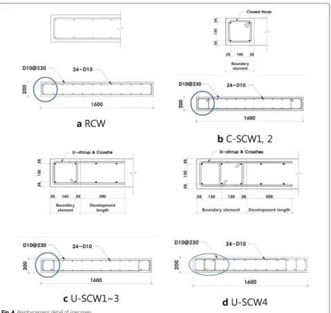
Fig. 4 Reinforcement detail of specimen.
Table 3 Specimen list.
fck (MPa) fy (MPa) Pu (MPa) B.E. length
(mm) Mn (kN m) Ver. rebar Hor. rebar End rebar
RCW 24 400 768 – 1012 D10@140 D10@230 –
C‑SCW1 210 2‑2‑D10
C‑SCW2 U‑SCW1 U‑SCW2 U‑SCW3
with a length of 1600 mm, thickness of 200 mm, and height of 61.6 m.
As shown in Table 2, structural experiments were conducted after seven full-size single-story walls were produced. The test specimens were classified into three forms—RCW, C-SCW, and U-SCW—depending on the wall end reinforcement details. RCW is a shear wall with no special boundary elements at the wall end, while test specimens of the C-SCW and U-SCW groups are special shear walls with special boundary elements installed at the wall ends. The latter were also differentiated by the confining methods of longitudinal reinforcement for special boundary elements. The test specimens of the C-SCW group, confined longitudinal reinforcements by using a closed hoop with seismic hooks as shown in in Fig. 3a. The test specimens of the
U-SCW group, meanwhile, confined longitudinal rein-forcements by using an overlapping hoop composed of a combination of U-bar and cross-tie as shown in in Fig. 3b. ACI-318 (ACI Committee 318 2014) was fol-lowed in detailing of the boundary zones for the spec-imens and the length of the U-bar is extended to the outside of the boundary element by the development length for deformed in tension.
Figure 4 shows cross-section details for the test speci-men. Though all test specimens were designed to show basically the same flexural strengths by bar manage-ment with the same vertical and horizontal steel rein-forcements, different flexural strengths were expected to be displayed as shown in Table 3. This was done by varying the lengths of special boundary elements and bar arrangement design based on the magnitude of Table 4 Material properties of the specimens.
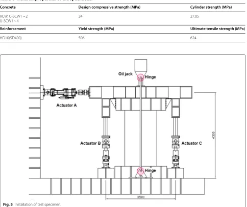
Concrete Design compressive strength (MPa) Cylinder strength (MPa)
RCW, C‑SCW1 ~ 2
U‑SCW1 ~ 4 24 27.05
Reinforcement Yield strength (MPa) Ultimate tensile strength (MPa)
HD10(SD400) 506 624
gravitational load applied to the cross section of a shear wall.
4 Materials
Design compressive strengths were 27 MPa; however, strengths at the time of testing ranged from 25.8 to 28.8 MPa. And typical bars of Grade 60 (420 MPa) and deformed No. 3 (9.5 mm) were used for longitudinal, horizontal, and vertical web reinforcement as well as boundary transverse reinforcement. Table 4 presents the material properties used in the specimens.
5 Testing and Instrumentation
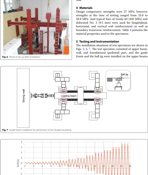
The installation situations of test specimens are shown in Figs. 5, 6, 7. The test specimen consisted of upper beam, wall, and foundational (pedestal) part, and the guide frame and the ball jig were installed on the upper beams Fig. 6 Photo of set up after installation.
Fig. 7 Guide frame installation for prevention of out‑of‑plane buckling.
to prevent out-of-plane buckling of walls as presented in Fig. 7.
To simulate gravitational load, shear force, and over-turning moment acting on the real wall, oil jacks were installed on the upper part of the test specimen and actu-ators on the strong wall and strong floor. Lateral load was transmitted by actuator A while moment was exerted by the see-saw movement of actuators B and C. To repro-duce the same load conditions as the actual load condi-tions, the load ratio applied to each of the actuators A, B, and C was maintained at 1:10.6:− 10.6, and hinges were installed at both ends of steel bars connecting oil jacks and the strong floor. The applied load was thus made to be oriented toward the center of the test specimen.
Figure 8 shows the repeated loads exerted on the test specimens by actuator A (ACI Innovation Task Group 1 and Collaborators 2001). With the difference in measure-ments by the LVDT installed at the top and bottom of the wall being set as the reference displacement, activating loads were exerted by the corresponding method of dis-placement control.
Figure 9 shows the instrumentation arrangement of LVDT and strain gauges in a specimen. Strain gauges were installed on the main and laterally confining bars around a place at half of the wall length from the shear wall bottom, where formation of plastic hinges was expected to occur. Three LVDTs were installed for slip measurement and displacement control for the test specimens.
6 Experiment Results
6.1 Cracking and Fracture Mode
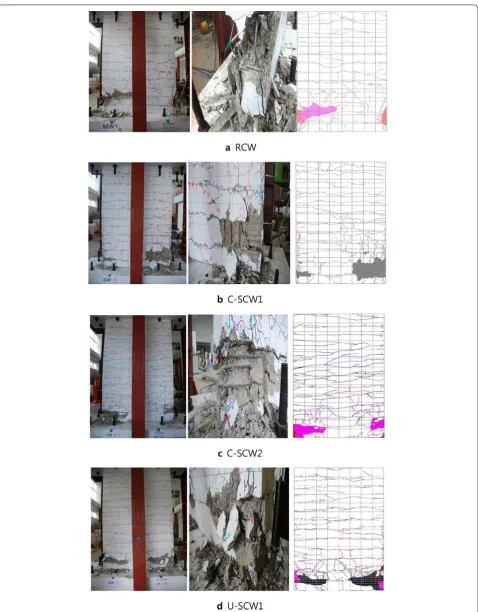
Figures 10, 11 shows the pictures of the final fracture and cracking extent for the test specimens. In all cases, within the range of a drift ratio of 0.2%, a lateral crack starts to form and the initial lateral crack proceeds to fractural-shear crack as the lateral crack produced upon actuation in positive and negative directions crisscross as the dis-placement is. Within a section of 1.0% in the drift ratio, vertical cracking of the compressive ends subsequently begins to occur, developing into concrete crushing of compressive ends as the trend of strength increase is reduced.
Only concrete crushing on the compressive side occurred upon final fracture without fracture of the longitudinal reinforcements on the tensile side of the RCW experimental wall. But crushing of concrete at the compressive end and fracture of the longitudinal rein-forcements at the end on the tensile side occurred simul-taneously in the case of test specimens of the C-SCW and U-SCW groups with special boundary elements at the ends. At this time, no significant differences were observed in the fracture mode of shear wall test speci-mens as a function of two types of binding methods of confining the longitudinal reinforcements. In both cases, no fracture of transverse reinforcements was pro-duced, and the binding of U-bar and cross tie was solidly maintained.
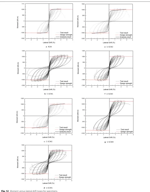
6.2 Moment—Drift Curves and Moment Strength
Figure 12 and Table 5 show a summary of experimental results and section analysis for test specimens. In Table 5, the term Pu is the vertical load acting on the section of the shear wall; the term Mn and Mn,test are the nominal flexural strengths at section estimated using the design strength and the material test strength; the term Mmax represents the actual, maximum strength of the fully-yielded system, and the term, DMmax is the displacement
ratio at that time. Dmax is the maximum drift ratio and μ represents ductility capacity defined as the ratio of Dmax and Dy. Wherein Dy is defined as the drift ratio at the point where the line connecting the origin and 60% Mmax
(0.6 Mmax) reaches Mmax (ASCE 2006).
for shear walls and used the design strengths as shown in Table 3.
As the longitudinal spacing of the transverse rein-forcement was narrowed, the manifestation point of the maximum strength tended to get delayed and deforma-tion-resisting capacity was also excellent in relation to bar arrangement of special boundary elements. On the
other hand, there was no significant difference in the deformation capacity of the shear wall due to the differ-ence between two confining methods.
6.3 Deformation Capacity and Energy Dissipation
Figures 13 and 14 show the results of the performance comparisons according to bar arrangement at the ends Table 5 Test results.
a Special shear walls as defined in ACI 318. b Ref.
c s: center-to-center spacing of transverse reinforcement.
s (mm)c P
u (kN) Pu
Agfck Mn (kN m) Mn,test (kN m) Mmax (kN m)
DMmax (%) Dmax (%) Mmax
Mn Mmax
Mn,test μ
RCW – 768 0.10 1012 1102.3 1135 1.43 2.0 1.12 1.03 6.9
C‑SCW1 50 1169 2.58 3.0 1.16 1.06 9.4
C‑SCW2a 65 1139 2.00 2.5 1.13 1.03 8.6
U‑SCW1 50 1125 2.47 2.5 1.11 1.02 8.6
U‑SCW2b 65 1148 2.07 2.5 1.13 1.04 8.6
U‑SCW3 80 1132 1.89 2.0 1.12 1.03 8.0
U‑SCW4 65 1152 0.15 1208 1349.6 1356 2.13 2.5 1.12 1.00 8.6
when the gravitational load corresponding to 10% of the resisting force in the axial direction of the cross section acts on the wall. After the maximum strength development in the 1.5% drift ratio, the RCW speci-men with no boundary elespeci-ments at the wall ends was destroyed with a strength drop of about 20% at a drift ratio of 2.0%. On the other hand, the trend of strength increase was continued in the specimens of the SCW group with the boundary elements even after a 1.5% drift ratio. When the longitudinal spacing of transverse reinforcements for boundary element was D/4, a dif-ference was seen in energy dissipation as the final drift ratios were 3.0% for C-SCW1 and 2.5% for U-SCW1, but the manifestation point for maximum strength and the change mode of stiffness degradation were similar.
With C-SCW2 and U-SCW2 (D/3), where trans-verse reinforcements are arranged at an interval of D/3 for boundary elements according to the regulations of ACI318-14, the final drift ratio, manifestation point of the maximum strength, trend of stiffness degradation, and the amount of dissipated energy are similar so that
no difference in wall performance is seen due to the confining method of transverse reinforcements. As a result, it was found that the wall end confining method using the overlapping hoops is similar to that of using the closed hoops.
Figure 15 shows comparisons of shear wall perfor-mance per longitudinal arrangement of transverse reinforcements when longitudinal reinforcements are laterally confined for boundary elements by using an overlapping hoop. U-SCW1, 2 and 3 had their trans-verse reinforcements arranged at the interval of D/4, D/3, and D/2.5, respectively, showing final drift ratios of 2.5, 2.5, and 2.0%, respectively. They showed very stable performance without drastic strength deteriora-tion within the same drift ratio until the final drift ratio was reached.
reinforcement as U-SCW2. By installing special bound-ary elements designed according to the magnitude of gravitational load applied at both ends of the walls, however, a strength boost of about 19% was expected (see Table 3).
According to the experimental results, as the magni-tude of applied gravitational load increased 1.5 times, the stiffness up to a drift ratio of 0.75% rose about 17% and the maximum strength grew about 18%.
Considering that the maximum displacement ratio of U-SCW2 and U-SCW4 specimens is equal to 2.5% and the energy dissipation of the U-SCW4 specimen is superior after maximum strength development, it can be seen that the lateral confinement method using the overlapping hoop has a stable restraining effect even if the magnitude of the gravity load acting on the cross section increases by 15%. If the section of the special boundary element is designed based on the magnitude of the gravity load according to the provisions speci-fied in the code, it can be expected that the use of the
overlapping hoop instead of the closed hoop can secure the required deformation capacity.
6.4 Strain Distribution of Steel Reinforcements
in the plastic hinge region from the bottom to 800 mm height, and all showed strain values within the elastic range.
7 Conclusions
7 RC wall specimens were fabricated and tested under combined axial load, shear and moment. The experimen-tal findings are summarized as follows:
1. An overlapping hoop using U bar and cross tie retained the core concrete binding force equivalent to a closed hoop. The wall with the overlapping hoop applied to the special boundary element showed sta-ble strain performance even with changes in gravita-tional load exerted on the cross section. Therefore, it seems that the overlapping hoop can be an effective alternative for rational seismic design of moderate to high seismicity zones to a closed hoop that constrain the longitudinal reinforcements of the special bound-ary element.
2. According to the comparison results of behavioral characteristics for the test specimens where longi-tudinal spacing of the transverse reinforcement for longitudinal reinforcement of special boundary ele-ments was D/4, D/3, and D/2.5, as the longitudinal spacing of the transverse reinforcements is narrower, the deformation performance of the shear walls is higher because the core concrete confinement effect increases. It is confirmed that the longitudinal spac-ing of transverse restrainspac-ing bars is inversely propor-tional to the deformation performance of the shear walls.
3. U-SCW3 is the case where the longitudinal spac-ing limit of transverse reinforcements specified in ACI318-14 is exceeded.
Because the final drift ratio Dmax of 2.0% sufficiently
satisfies the condition for drift limit on the level of
life safety (Applied Technology Council 1996) in this
case as well, additional studies appear necessary on structural performance per level through the study of relationships between longitudinal spacing for
verse reinforcements at the wall end and wall behav-ior.
4. Though linearity was observed for the strains of ver-tical steel reinforcements within the lateral drift ratio of 0.75%, nonlinear appearance was exhibited where tensile strains did not increase in sections other than
the boundary elements after yielding. The assump-tion of a displacement-based design method in which the strains of a wall cross section exhibit linear distri-bution, thus appears to require re-examination.
Authors’ contributions
All authors read and approved the final manuscript.
Author details
1 School of Architecture, Chonnam National University, Gwangju 61186,
Republic of Korea. 2 Public Housing Research Department, Land & Housing
Institute, Daejeon 34047, Republic of Korea. 3 Dept. of Plant Architectural
Engineering, Kyonggi University, Suwon 443‑760, Republic of Korea.
Acknowledgements
This work was supported by Land and Housing Institute and the National Research Foundation of Korea (NRF) Grant funded by the Korea Government (MSIP) (No. NRF‑2017R1A2B3008463).
Competing interests
The authors declare that they have no competing interests.
Availability of data and materials
Not applicable.
Consent for publication
Not applicable.
Ethics approval and consent to participate
Not applicable.
Funding
Not applicable.
Publisher’s Note
Springer Nature remains neutral with regard to jurisdictional claims in pub‑ lished maps and institutional affiliations.
Received: 26 February 2018 Accepted: 29 January 2019
References
ACI Committee 318. (2014). Building code requirements for structural concrete (ACI 318-14) and commentary. Farmington Hills, MI: American Concrete Institute.
ACI Innovation Task Group 1 and Collaborators. (2001). Acceptance criteria for moment frames based on structural testing (ACI ITG/T1.1-01) and commen-tary (ACI ITG/T1.1R-01). Farmington Hills, MI: American Concrete Institute. Applied Technology Council. (1996). Seismic evaluation and retrofit of concrete
buildings (ATC-40). Redwood City: Applied Technology Council. Architectural Institute of Japan. (2010). AIJ standard for structural calculation of
reinforced concrete structures. Tokyo: Architectural Institute of Japan. Architectural Institute of Korea. (2011). Seismic performance evaluation of shear
wall structural system with relaxed reinforcement details. Seoul: Architec‑ tural Institute of Korea.
Architectural Institute of Korea. (2013). Experimental study for revising provisions for special structural walls. Seoul: Architectural Institute of Korea. Architectural Institute of Korea. (2016). Korean building code-structure: KBCS.
Seoul: Architectural Institute of Korea.
ASCE. (2006). Seismic rehabilitation of existing buildings, ASCE Standard ASCE/SEI 41-06. Reston: American Society of Civil Engineers.
British Standards Institution. (2004). European Standard EN 1998-1:2004: Eurocode8: design of structures for earthquake resistance. London: British Standards Institution.
Chun, Y.‑S., Kim, S.‑Y., & Lee, W.‑C. (2011). Development of relaxed reinforcement detail for special structural wall to mitigate height restrictions. Daejeon: Land and Housing Institute.
Chun, Y.‑S., Lee, K.‑H., Lee, H.‑W., Park, Y.‑E., & Song, J.‑K. (2013). Seismic perfor‑ mance of special shear wall structural system with effectively reduced reinforcement detail. Journal of the Korea Concrete Institute,25(3), 271–281. Computers and Structures, Inc. (2006). PERFORM-3D; Nonlinear analysis and
performance assessment for 3D structures. Berkeley, CA: Computers and Structures Inc.