© 2017 IJSRST | Volume 3 | Issue 7 | Print ISSN: 2395-6011 | Online ISSN: 2395-602X Themed Section: Science and Technology
Design and Optimization of Helicopter Rotor Blade Using
Different Materials
S Mohan Kumar
1, J Narsaiah
2, Pininti Sairam Reddy
31
Department of Mechanical Engineering, AVN Institute of Engineering & Technology, Hyderabad, Telangana, India
2
Department of Mechanical Engineering, AVN Institute of Engineering & Technology, Hyderabad, Telangana, India
3PG Student, Department of Mechanical Engineering, AVN Institute of Engineering & Technology, Hyderabad, Telangana,
India
ABSTRACT
The blades of a helicopter are long, narrow airfoils with a high aspect ratio, a shape that minimises drag from tip vortices. They contain a degree of washout that reduces the lift generated at the tips, where the airflow is fastest and vortex generation. Rotor blades are made out of the variety of materials, including aluminium, composites, and steel or titanium, with abrasion shields along the leading edge. The helicopter rotor hub is powered by the engine, and the rotor blades are attached to the centre. The motion of blade is controlled by the helicopter rotor system. The main rotor blade mainly affected by the air flow for rotation of the blade and the influence of aerodynamic force and a centrifugal force applying to blade has been considered. The dynamic characteristics analysis of rotor blade is mainly involved in the vibration control. The objective is to calculate the natural frequency and operating frequency of rotor blade and by modulating those frequencies and avoiding resonance at the rotational speed. Thus the vibrations of the helicopter may reduce. In this project, the three-dimension model of helicopter rotor blade is modelled in NX-CAD and imported into ANSYS software to analyse the strength, and dynamic characteristics of rotor blade have been developed. The static force and the dynamic attributes about rotor blade have been analysed with ANSYS software for different materials (aluminium alloy and composite materials). During the analysis of dynamic characteristic, the influence of aerodynamic force and a centrifugal force applying to blade has been considered.
Keywords : Rotor Blade, NX-CAD, Static & Dynamic Forces.
I.
INTRODUCTION
The Wings Of The Aeroplane Create A Lift Force When They Move Through The Air. As We Are Known, During Flight, Four Forces Are Acting On The Helicopter Or Aircraft, And Those Are LIFT, DRAG, THRUST, And WEIGHT. To Make The Wings Move Through The Air, The Plane Itself Has To Move. A Helicopter Works By Having Its Wings Move Through The Air While The Body Stays Still. The Helicopter's Wings Are Called Main Rotor Blades. The Shape And The Angle Of The Blades Move Through The Air Will Determine How Much Lift Force Is Created. After The Helicopter Lifted Off The Ground, The Pilot Can Tilt The Blades, Causing The Helicopter To Tip Forward, Backward Or Sideward.
Helicopters Are Manufactured In Many Sizes And Shapes, But Most Share The Same Primary Components. These Components Include A Cabin Where The Payload And Crew Are Carried; An Airframe, Which Houses The Various Parts, Or Where Components Are Attached; A Power Plant Or Engine; And A Transmission, Which, Among Other Things, Takes The Power From The Engine And Transmits It To The Main Rotor, Which Provides The Aerodynamic Forces That Make The Helicopter Fly. Then, To Keep The Helicopter From Turning Due To Torque, There Must Be Some Anti-Torque System. Finally, There Is The Landing Gear, Which Could Be Skids, Wheels, Skis Or Floats.
II.
LITERATURE REVIEW
Xiang-Lin Ma, Zhi-Qing Zhang, Those Three-Estimation Compelled Parts Show For Helicopter Rotor Edge Require Been Worked With APDL Tongue, That Point Utilizing This Model, Those Static Quality And The Segment Qualities Something Like Rotor Edge Require
Been Investigated With ANSYS Programming
Gathering. All Through The Investigation Of Dynamic
Trademark, Those Impact Of Aeromechanic
Essentialness And Extended Imperativeness Applying Will Be Sharpened Steel Require Been Completely Observed. Also, The Full Outline Of Rotor Edge Requires Been Introduced In This Paper.
Actuator Configuration For That Dynamic Trailing Edge Of A Helicopter Rotor Edge Toward Christoph K. Maucher1, Boris An. Grohmann1, Subside Jänker1, Andree Altmikus2, Flemming Jensen3, Horst Baker, Today, Helicopters Indeed Going Currently White Collar Of The Way Beginning With Their Common Impact Review External Noise, Fuel Use In Addition Emissions, Their Low Passee Comfort Concerning Lodge Upheaval Moreover Vibrations Additionally Their Confined Execution For Views Flight Envelope, Speed Moreover Degree. A Champion Around Those Basic Wellsprings Over Upheaval Moreover Vibrations May Be The Key Rotor, Especially Completed Fast Propel Likewise Plummet Flight. Therefore, Developments In Moved Rotor Control Would Investigate. Unique Honed Steel Control (IBC) Frameworks Tolerance On Diminishing Vibration, Noise Besides Shaft Vitality Use. If Control Every Rotor Edge Individually, On-Blade Incitation Segments In Perspective Of Vivified Materials The Table Positive Position Condition Secured Nearby Weight, Control Use Also Exchanges Pace Contrasted With Frameworks Inciting The Individual's Rotor Edge Root. The Mossy Cup Oak Propelled Methodologies As Such Need Aid The Regulate Turn Idea And The Trailing Edge Fold. That Theme From Claiming This Paper May Be Another Idea For An IBC Actuator, Those Animated Trailing Edge. The Dynamic Trailing Edge Particular Idea Understands A Morphing Cross Area For A Helicopter Rotor Edge. The Trailing Edge Of The Airfoil Has The Ability On Diverting Upwards Furthermore Downwards. Comparable Of The Trailing Edge Flaps, Those Consumed Plans With Turn The Sharpened Steel Aero Elastically Utilising The Servo Effect, I.E. The Change
In Air Motion Facilitating Pitching Minute Twist The Rotor Edge.
Structural Analysis Of The Main Rotor Blade For A Light Helicopter - Case Of Hovering Flight Mode By Diana Cazangiu, Those Aviation Industry Arrangements Starting With The Start With Structures With Extraordinary Necessities Similarly As Amazing Lightweight Also Withstanding With A Huge Number From Claiming Load Situations. Flight Science Imperatives Prompt Supplementary Restrictions, Those Outcomes Constantly The Mind-Boggling State Will Support The Fuselage, Those Rotor Blades Alternately The Wings Skin. This Paper Displays A Static Structural Dissection Of The Fundamental Rotor Sharpened Steel For The Light Helicopter. To Recreate The Mechanical Conduct Technique Of The Blade, A Limited Components Strategy Might Have Been Utilised. An Instance From Claiming Hovering Flight Mode Might Have Been Acknowledged.
III.
PROBLEM DEFINITION & SOLUTION
METHODOLOGY
The Fundamental Rotor Edge For The Most Part Influenced By The Wind Current For A Revolution Of Sharp Edge And The Impact Of Streamlined Constrain And Radial Compel Applying To Cutting Edge Has Been Completely Considered. The Dynamic Qualities Examination Of Rotor Sharp Edge Is For The Most Part Engaged With The Vibration Control. The Goal Is To Figure The Common Recurrence, And Working Recurrence Of Rotor Sharp Edge Is Regulating Those Frequencies And Maintaining A Strategic Distance From Reverberation At A Rotational Speed, In This Manner The Vibrations Of The Helicopter May Decrease.
IV.
3D MODELING OF HELICOPTER ROTOR
BLADE
NX, Previously Known As NX-CAD Alternately As A Rule Exactly U-G, Is A Propelled High-End
CAD/CAM/CAE Programming Bundle Initially
Produced NX-CAD, In Any Case Since 2007 By Siemens PLM Programming.
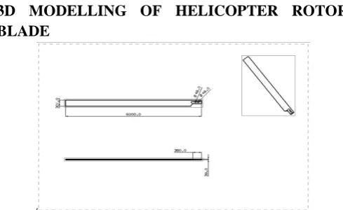
3D MODELLING OF HELICOPTER ROTOR BLADE
Figure 1: Shows The Symmetric Airfoil Sketch
Figure 2: Shows The 3D Model Of Swept Forward Wing
FINITE ELEMENT ANALYSIS OF HELICOPTER ROTOR BLADE
Limited Component Demonstrating (FEM) And Limited Component Investigation (FEA) Are Two Most Well Known Mechanical Designing Applications Offered By Existing CAE Frameworks. This Is Credited To The Way That The FEM Is Maybe The Most Prevalent Numerical Strategy For Taking Care Of Building Issues. The Strategy Is Sufficiently General To Deal With Any Unpredictable State Of Geometry (Issue Area), Any Material Properties, Any Limit Conditions And Any Stacking Conditions. The Sweeping Statement Of The FEM Fits The Investigation Prerequisites Of The Present
Complex Building Frameworks And Outlines Where Shut Shape Arrangements Are Administering Harmony Conditions Are Not Accessible. What's More It Is A Productive Outline Device By Which Architects Can Perform Parametric Plan Contemplating Different Cases (Distinctive Shapes, Material Burdens And So On.) Examining Them And Picking The Ideal Outline.
FINITE ELEMENT METHOD (Limited Component Technique):
Those FEM Will Be Numerical Examination Strategy For Getting Surmised Replies To Totally Combination From Claiming Fabricating Issues. The Method Began In The Aeromechanic Profession Likewise An Mechanical Assembly On Analyze Worries Clinched Alongside Jumbled Airframe Structures. It Turned Into Crazy About The Thing That Might Have Been Known As The Schema Examination Techno Babble Used As An And Only Flying Machine Want. The Technique Need Picked Dependent Upon Pervasiveness "Around The Two Masters Also Masters And Then Afterward Such An Extensive Number Of Advancements Codes Need Aid Made To Totally Combination About Issues.
STRUCTURAL ANALYSIS:
MATERIAL PROPERTIES:
Aluminum Alloys -2014-Mechanical Properties: Young’s Modulus = 70Gpa
Yield Strength = 414 Mpa Poison’s Ratio = 0.3
Density = 2700 Kg/M3
3D Model Of The Helicopter Rotor Blade Was Developed In UNIGRAPHICS. The Model Was Converted Into A Para Solid To Import In ANSYS.
Figure 3: Shows The Geometrical Model Of Helicopter Rotor Blade
RESULTS
Figure 4: Total Deflection Of Helicopter Rotor Blade
Figure 5: Von Mises Stress Of Helicopter Rotor Blade
V.
DYNAMIC ANALYSIS OF HELICOPTER
ROTOR BLADE
Modal ANALYSIS:
Modal Investigation Might Have Been Conveyed Out To Focus The Common Frequencies Furthermore Mode Shapes Of A Structure In The Recurrence Go For 0 -12Hz.
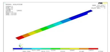
Mode Shape [email protected] Hz
Figure 6: Shows Mode Shape [email protected] Hz For Helicopter Rotor Blade.
From The Modal Analysis,
It Is Observed That The Maximum Mass
Participation of 69kgs Is Observed In X-Dir For The Frequency of 5.4Hz.
It Is Observed That The Maximum Mass
Participation Of 65kgs And 25kgs Are Observed In Z-Dir For The Frequency Of 0.787Hz And 4.6Hz.
Figure 7: Von Mises stress of helicopter rotor blade
STATIC ANALYSIS OF COMPOSITE HELICOPTER ROTOR BLADE
Figure 8: Von Mises stress of helicopter rotor blade
DYNAMIC ANALYSIS OF HELICOPTER ROTOR BLADE
MODAL ANALYSIS:
Modal analysis was carried out to determine the natural frequencies and mode shapes of a structure in the frequency range of 0 -12Hz.
Boundary Conditions:
Blade is arrested on the bolting locations are fixed in all dof which is connected to hub.
Figure 9. shows the boundary conditions of helicopter rotor blade
Mode shape [email protected] Hz
Figure 10: shows Mode shape [email protected] Hz for helicopter rotor blade
HARMONIC RESPONSE ANALYSIS
Any maintained cyclic load will prepare a supported cyclic reaction (a symphonious response) Previously, A
structural framework. Symphonious reaction
examination provides for you the capacity on foresee the managed dynamic self-destructive considerations and conduct for your structures, hence empowering you to confirm it or not your outlines will effectively beat resonance, fatigue, and different unsafe impacts for constrained vibrations.
The system to An full symphonious reaction dissection comprises for three fundamental steps:
5. Raise the model.
Figure 11 : Von Mises stress of helicopter rotor blade
STATIC ANALYSIS OF COMPOSITE HELICOPTER ROTOR BLADE
OBJECTIVE:
Structural static Investigation need been performed on the composite helicopter rotor edge structure toward applying the precise speed what’s more gravity. The bolting areas would alter on the whole dof.
RESULTS: Deflections:
Figure 12: Deflection in X-dir of helicopter rotor blade
Figure 13. Deflection in Y-dir of helicopter rotor blade
Figure 14. Deflection in Z-dir of helicopter rotor blade
Figure 15: Total Deflection of helicopter rotor blade
Table 1. Shows the max. Deflection and Max. Stress
From the over comes about it is watched that those vital anxieties values 144MPa, 52MPa, and 40MPa would less the central anxieties values of the material 800MPa, 60MPa, Furthermore 74MPa for individually 1st, second Also 3rd central focuses on. Subsequently as stated by those greatest stresses Theory, those composite helicopter rotor edge plans will be safe for those over working loads.
DYNAMIC ANALYSIS OF HELICOPTER ROTOR BLADE
MODAL ANALYSIS:
Modal analysis was carried out to determine the natural frequencies and mode shapes of a structure in the frequency range of 0 -12Hz.
Boundary Conditions:
Blade is arrested on the bolting locations are fixed in all dof which is connected to hub.
Figure 17: shows the boundary conditions of helicopter rotor blade
Total helicopter main rotor blade weight observed is 82kgs.
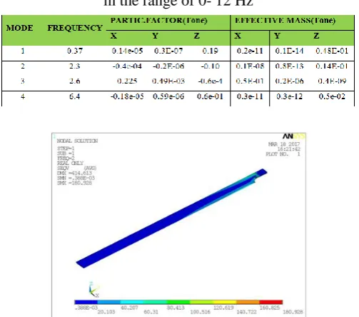
Table 2 .frequencies and mass participations for modes in the range of 0- 12 Hz
HARMONIC RESPONSE ANALYSIS
Whatever managed cyclic load will generate a supported cyclic reaction (a symphonious response) done An structural framework. Symphonious reaction examination provides for you the capacity will anticipate the maintained element conduct from claiming your structures, Subsequently empowering you will check if alternately not your outlines will effectively beat resonance, fatigue, What's more different destructive impacts of constrained vibrations.
The system for An full symphonious reaction Investigation comprises about three fundamental steps: 7. Fabricate the model.
8. Apply loads and get the result. 9. Survey those outcomes.
From the modal analysis,
Table 3. Frequencies and mass participations for modes in the range of 0- 12 Hz
Figure 18:Von Mises stress of helicopter rotor blade
Table: shows the deflections and Von Mises stress for critical frequencies
carbon/epoxy) 800MPa, 90MPa, and 70MPa for separately 1st, second furthermore 3rd central anxieties.
As stated by that Von Mises Theory, those Von Mises stress from claiming helicopter rotor edge during frequencies 2Hz will be Hosting over those yield quality of the material. Consequently those outlines of helicopter rotor edge may be safe to those over operating stacking states
VI.
RESULTS AND DISCUSSIONS
In the present project, the helicopter rotor blade has been studied for structural behavior and optimized for different materials (aluminum and composite materials). The helicopter rotor blade was studied for 3 different materials:
Aluminum
HM carbon/ epoxy
E-glass/ epoxy
CASE-1: Structural analysis of helicopter rotor blade with aluminum material:
From static analysis,
From the static analysis results it is observed that the maximum VonMises stress observed is 172 MPa. The maximum stress is observed on the bolting location. The yield strength of the material is 414 MPa. According to the VonMises Stress Theory, the VonMises stress of helicopter rotor bladeis having less stress than the yield strength of the material (aluminum alloy).
From the modal analysis, Starting with those over modal examination outcomes it will be watched that just 3 common frequencies exists in the working extend for 0-12 Hz. Downright helicopter fundamental rotor sharpened steel weight watched is 111kgs.
It may be watched that the most extreme impostor cooperation for 69kgs will be watched over X-dir for those recurrence from claiming 5. 4Hz.
It may be watched that the most extreme impostor investment about 65kgs Also 25kgs would watched in Z-dir to those recurrence of 0. 787Hz Furthermore 4. 6Hz.
From the harmonic analysis
Harmonic analysis was carried out on the helicopter rotor blade to determine the deflections and stress of a structure in the critical frequency range of 0 -12 Hz.
From the harmonic analysis results it is observed that the critical frequencies 6 Hz, is having stresses of 295MPa respectively. The yield strength of the material used for helicopter rotor blade is 414MPa. According to the VonMises Stress Theory, the VonMises stress of helicopter rotor blade at frequencies 6 Hz is having less stresses than the yield strength of the material.
CASE-2: Structural analysis of helicopter rotor blade with HM carbon/ epoxy material:
From static analysis,
From those outcomes it may be watched that the central focuses on qualities 112MPa, 50MPa, Also 29MPa would less those central anxieties qualities of the material 870MPa, 54MPa, What's more 30MPa with individually 1st, second and 3rd central anxieties. Subsequently as stated by the greatest anxiety Theory, the composite helicopter rotor edge plan may be safe to the over working loads.
From the modal analysis,
Starting with the modal examination effects it may be watched that main 5 regular frequencies exists in the working range for 0-12 Hz. Downright helicopter fundamental rotor sharpened steel weight watched may be 66kgs.
It may be watched that the greatest impostor cooperation of 40kgs may be watched done X-dir for those recurrence about 2. 3Hz.
It may be watched that those most extreme impostor support of 38kgs Also 11kgs would watched to Z-dir to those recurrence for 0. 33Hz what’s more 2. 1Hz. From the harmonic analysis,
Harmonic analysis was carried out on the helicopter rotor blade to determine the deflections and stress of a structure in the critical frequency range of 0 -12 Hz.
CASE-3: Structural analysis of helicopter rotor blade with E-glass/ epoxy material:
From static analysis,
From the results it is observed that the principal stresses values 144MPa, 52MPa, and 40MPa are less than the principal stresses values of the material 800MPa, 60MPa, and 74MPa with respectively 1st, 2nd and 3rd principal stresses. Hence according to the Maximum Stress Theory, the Composite Helicopter rotor blade design is safe for the above operating loads.
From the modal analysis,
From the modal examination effects it is watched that main 4 common frequencies exist in the operating extend about 0-12 Hz. That downright weight of the control straight will be 82 kg.
It may be watched that the greatest impostor cooperation of 50kgs may be watched done X-dir for those recurrence about 2. 3Hz.
It may be watched that those most extreme impostor support of 48kgs Also 14kgs would watched to Z-dir to those recurrence for 0. 33Hz what’s more 2. 1Hz.
From the harmonic analysis,
From the harmonic analysis results it is observed that the principal stresses of 2Hz frequency values 95MPa, 18MPa and 5MPa are less than the principal stresses values of the material(HM carbon/epoxy) 800MPa, 90MPa, and 70MPa with respectively 1st, 2nd and 3rd principal stresses. According to the VonMises Stress Theory, the VonMises stress of helicopter rotor blade at frequencies 2Hz is having less stresses than the yield strength of the material.
Comparison of aluminum alloy, HM carbon/Epoxy and E glass/ Epoxy materials
Hence the design of helicopter rotor blade is safe for the above operating loading conditions in all 3 materials.
VII.
CONCLUSION
In the display project, the helicopter rotor edge need been contemplated for structural conduct What's more
optimized to distinctive materials (aluminum
Furthermore composite materials).
In this work, the three-dimension model from claiming helicopter rotor edge might have been demonstrated for NX-CAD Also foreign under ANSYS product should examine quality Furthermore dynamic aspects of rotor edge need been formed. The static quality and the changing aspects regarding rotor edge were investigated with ANSYS product for separate materials (aluminum compound Furthermore composite materials).
Starting with the examination it is reasoned that helicopter rotor edge needs focuses on and deflections inside the configuration breaking points for those the sum three materials (aluminum and composite materials). Starting with those outcomes we might presume that those carbon/ epoxy material helicopter sharpened steel need lesquerella weight furthermore exceptional component of security.
VIII.
REFERENCES
[1]. Jiang, Nian-zhao & Ma, Xiang-lin & Zhang, Zhi-qing. (2017). “The Dynamic Characteristics Analysis of Rotor Blade Based on ANSYS”. [2]. Rasuo, B., Design, Fabrication and Testing of the
Helicopter Tail Rotor Blade from Composite
Laminated Materials, 13th International
Conference on Composite Materials, ICCM-13, June 25-29, 2001, Beijing, China, Yao Zhang (Ed.)
[3]. Structural analysis of the main rotor blade for a light helicopter - case of hovering flight mode by diana cazangiu, Volume XXIII (XIII), 2014/1, DOI: 10.15660/AUOFMTE.2014-1.2964
[4]. L. Walsh, Joanne. (1991). Performance
optimization of helicopter rotor blades.
[5]. Actuator design for the active trailing edge of a helicopter rotor blade by Christoph K. Maucher1, Boris A. Grohmann1, Peter Jänker1, Andree Altmikus2, Flemming Jensen3, Horst Baker, http://hdl.handle.net/20.500.11881/233
[6]. Srinivasan, G. R., and McCroskey, W. J.,
“Navier-Stokes Calculations of Hovering Rotor
[7]. Bell Helicopter TEXTRON. OH-58D Air Vehicle Technical Description Data; report no. 406-099-026; Fort Worth, TX, May 1984.
[8]. Bell Helicopter TEXTRON. Model 406
Performance Analysis; report no. 406-099-080; FortmWorth, TX, August 1983.
[9]. Kim, K. C. “Analytical Investigation into the Helicopter Vibration Resulting From Main Rotor Blade (MRB) Ballistic Damage”; ARL-TR-1985; U.S. Army Research Laboratory: Aberdeen Proving Ground, MD, June 1999.
[10]. Li, Leihong. 2008. “Structural design of composite rotor blades with consideration of manufacturability, durability, and manufacturing uncertainties”.
[11]. Abdelkader Nour, Mohamed Tahar Gherbi, Yon Chevalier, “Modes shape and harmonic analysis of different structures for helicopter blade,” University of Granada, 12-15 September 2012. [12]. Wan, T., and Wu, S. W., “Aerodynamic Analysis