REVIEW PAPER: STUDY ON A COMPARATIVE
STUDY OF BUBBLE DECK SLAB AND
CONVENTIONAL DECK SLAB
Mr. Devyanshu Jain
1, Miss. Nidhi Gupta
21
Department of Civil Engineering, RKDF Institute of Science & Technology (India)
2
Head of Department of Civil Engineering, RKDF Institute of Science & Technology, (India)
ABSTRACT
When designing a reinforced concrete structure, a primary design limitation is the span ofthe slab between
columns. Designing large spans between columns often requires the use ofsupport beams and/or very thick
slabs, thereby increasing the weight of the structure by requiringthe use of large amounts of concrete. Heavier
structures are less desirable than lighter structures in seismically active regions because a larger dead load for
a building increases the magnitude of inertia forces the structure must resist as large dead load contributes to
higher seismic weight. Incorporating support beams can also contribute to larger floor-to-floor heights which
consequently increases costs for finish materials and cladding.
A new solution to reduce the weight of concrete structures and increase the spans of two-way reinforced
concrete slab systems was developed in the 1990s in Europe and is gaining popularity and acceptance
worldwide. Plastic voided slabs provide similar load carrying capacity to traditional flat plate concrete slabs
but weigh significantly less. This weight reduction creates many benefits that should be considered by engineers
determining the structural system of the building.Plastic voided slabs remove concrete from non-critical areas
and replace the removed concrete with hollow plastic void formers while achieving similar load capacity as
solid slabs. Voided slab principles have been applied in different applications dating back to the early
1900s.Similary the reduction of concrete in bridge deck modal (light weight Pedestrian Bridge).In this thesis
work our main focus on the reduction of concrete of bridge deck. So first we know about different type of parts
of the bridge.
I. INTRODUCTION
The BubbleDeck method for the two directions reinforced composite concreteslab with gaps was invented in
Denmark, it is licensed and it was conceived to achieve saving of concrete and energy in buildings construction.
The composite slabs are made of Bubble Deck type slab elements with spherical gaps, poured in place on
transversal and longitudinal directions.
By introducing the gaps leads to a 30 to 50% lighter slab which reduces the loads on the columns, walls and
foundations, and of course of the entire building. ”BubbleDeck” slab elements are plates with ribs on two
directions made of reinforced concrete or precast concrete with spherical shaped bubble. These slab elements
reinforcement of the plates is made of two meshes one at the bottom part and one at the upper part that can be
tied or welded. The distances between the bars correspond to the dimensions of the bubbles that are to be
embodied and the quantity of the reinforcement from the longitudinal and the transversal ribs of the slab. The
two mashes are connected after placing the spheres into places in order to form a rigid shell.
The bubbles are made by embodying high density polypropylene in the concrete, arranged according to the
project and placed between the reinforcement meshes. The material that are made of don’t react chemically with
the concrete orthe reinforcement, it has no porosity and has enough rigidity and strength to take over the loads
as much as from the pouring of the concrete as from the subsequent phases of this process.
II. OBJECTIVE
The main objective of this study is to investigate the potential use of granite waste in concrete as replacement
for coarse aggregate and is to arrive at a suitable mix design for the application of discarded granite waste as a
partial replacement of coarse aggregate in concrete; and to test and analyze the workability, density of hardened
concrete, compressive and flexural strength, of concrete of grade M30.
III. LITERATURE SURVEY
The bubble deck slab is a revolutionary biaxial concrete floor system developed in Europe. High-density
polyethylene hollow spheres replace the ineffective concrete in the centre of the slab ,thus decreasing the dead
weight and increasing the efficiency of the floor. These biaxial slabs have many advantages over a conventional
solid concrete slab: lower total cost, reduced material use, enhanced structural efficiency, decreased construction
time and is a green technology.
Through tests, models and analysis from a variety of institutions,bubbledeck was proven to be superior to the
traditional solid concrete slab. The reduced dead load makes the long term response more economical foe the
building while offsetting the slightly increased deflection of the slab.However, the shear and punching shear
resistance of the bubble deck floor is significantly less than a solid deck since resistance is directly related to the
depth of concrete. Design reduction factors have been suggested to compensate for these difference in strength.
This system is certified in the Netherlands, the unitedkingdom, Denmark and Germany.
TINA LAI (2009) have studied “Structural behavior of bubble deck slab and their application to lightweight
bridge deck” investigated ,after verifying the validity of the prior research through a finite element analysis of
an office floor in SAP2000,the bubble deck slab was tested for a pedestrian bridge deck. Bridge design is
dominated by the dead weight of the structure and by concentrated stresses from vehicular traffic. This new slab
can solve both of these problems by reducing weight with the plastic spheres and by applying it to a pedestrian
bridge to limit the high stresses. A set of bridge deck were modeled and analyzed in sap 2000 for this study.
L.V.HAI (2009) Studied “The experimental analysis of bubble deck slab using modified elliptical balls and
desisus the new prefabricate construction technology using bubble deck slab” is recently applied in many
industrial projects in the world. Bubble deck slab uses hollow spherical ball made by recycled plastic and
which does not contributed to the structural performance. This hence reduce significantly the structural
selfweight.in this paper ,the experimental result of bubble deck slab subjected to static loading are presented.
The effects of various factors to the behaviors of bubble deck slab are considered, such as the concrete strength,
the shape and diameter of plastic balls, the size of reinforcing mesh at top and bottoming order to demonstrate
the superiority and advances of mentioned technology, the improving of the plastic ball’s shape by using hollow elliptical balls for better load-bearing capacity in Bubble Deck is also presented in details. The research results
show the effectiveness and feasibility of the application of Bubble Deck in the construction works Ho Chi Minh
City, Vietnam
Vijay Kumar(2010)studied the “Structural Behavior of Bubble Deck Slab” investigated the Bubble deck slab is
a method of virtually eliminating all concrete from the middle of a floor slab, which is not performing any
structural function, thereby dramatically reducing structural dead weight. High density poly ethylene hollow
spheres replace the in-effective concrete in the center of the slab, thus decreasing the dead weight and increasing
the efficiency of the floor. By introducing the gaps leads to a 30 To50% lighter slab which reduces the loads on
the columns, walls and foundations, and of course of the entire building. The advantages are less energy
consumption - both in production, transport and carrying out, less emission - exhaust gases from production and
transport, especially CO2 .The aim of this paper is to discuss about various properties of Bubble deck slab based
on the various studies done abroad. Moment, deflection and stress distributions are verified using Finite Element
Method (FEM) in SAP2000.
Corey J Midriff (2013) has studied about “Plastic Voided Slab Systems: Applications and Design investigated
the Reinforced concrete slabs are one of the most common components in modern building construction.
Reinforced concrete slabs with plastic voids slabs are a new and innovative type of structural, concrete slab
system developed to allow for lighter self-weight of the structure while maintaining similar load carrying
capacity of a solid slab. Plastic voided slabs are capable of reducing the amount of concrete necessary to
construct a building by 30 percent or more. This reduction can be beneficial in terms of financial savings as
well as building performance. This report examines a two-way, reinforced concrete slab with plastic voids
construction in comparison to traditional flat plate reinforced concrete slab construction. The design processor
plastic voided slabs is directly compared with traditional two-way flat plate reinforced concrete slabs through a
design comparison of typical bays of 20’ by 20’ (6m by 6m), 25’ by 25’(7.6m by 7.6m), 30’ by 30’ (9m by 9m) and 35’ by 35’ (10.7m by 10.7m). The traditional slab design process follows the ACI 318-11 Building Code
Requirements for Structural Concrete.
Gilani A, and juntunen (2013) have studied about “Spherical void formers in concrete slabs” investigated the
Large span concrete flat-slab systems with internal spherical void formers (SVF) have been used in Europe for
over a decade. They are bi-axially reinforced concrete flat-slab systems with a grid of internal spherical void
formers. This paper addresses three issues associated with SVF slab systems: their shear resistance, their
short-term elastic deflections and their economical value in a South African context. Due to the “loss” (or reduction)
of aggregate interlock required for shear resistance in SVFslabs, the design requirements of the reinforced
concrete design code are affected. Research at the Technical University of Darmstadt (TUD) in Germany proved
suggests a greater factor of 0,85 when taking into account the shear capacity of the permanent steel cages that
hold the spheres in position in some SVF slab systems.
IV. METHODOLOGY
The method of design and analysis of the bubble deck bridge slab are two types which are elucidated below.
1) DESIGEN AND ANALYSIS IN LABROTARY
2) DESIGEN AND ANALYSIS IN SOFTWARES
4.1 Desigen and Analysis in Laboratary
The design of bubble deck slab in the laboratory consist different steps. The bubble deck slab is the combination
of reinforced concrete and PVC balls. The mixer of cement sand and aggregate on the basis of INDIAN
STANDARAD (concrete mix proportioning) 10262:2009.
Step 1 : Dimension of mould of bubble deck slab – 0.66mx0.33mx0.14m
Volume of mould of bubble deck slab – 0.02772m3
Step 2: Dimension of Plastic balls (diameter)= 0.0625m
Radius = 0.031m
Volume of sphere = 4/3xπxr3
Volume of sphere of 24 ball =0.0035m3
Volume of design for mix proportioning = vol. of mould-volume of sphere
= 0.2772-0.0035
= 0.02422m3
Concrete of mix proportion for M25
4.2 Types of Material and Their Shape and Size
For the design of bubble deck slab the main material is the cement sand and aggregate .for the better result we
done the test of different type of material
2.2.1 Concrete
4.2.2 HDPE Balls
A linear polymer, High-density polyethylene (HDPE) is prepared from ethylene by a catalytic process. The
absence of branching result in a form more closely packed structure with a higher density and somewhat higher
chemical resistance then LDPE(low-density polyethylene).HDPE is also somewhat harder and more opaque and
it can withstand rather higher temperatures(1200 Celsius for short periods,1100 Celsius continuously).
4.2.3 Preparation of reinforcement mesh
We know that concrete are provided in the bubble deck slab for the compressive zone and the steel bar are
Plates-Preparation of mesh Plates -Combination of HDPE Balls with mesh
The size of steel bar vertical direction is 62cm and in the horizontal direction is 24 cm and the spacing between
is 6.5cm and the diameter of bar is 8mm.and the diameter of HDPE ball is 6.5cm.the combination of bar and
ball are show in fig. are given below.
4.4 Preparation of Concrete
Production of quality concrete requires meticulous care exercised at every stage of manufacture of concrete. It
is interesting to note that the ingredients of good concrete and bad concrete are the same. If meticulous care is
not exercised, and good rules are not observed, the resultant concrete is going to be of bad quality. With the
same material if intense care is taken to exercise control at every stage, it will result in good concrete.
Therefore, it is necessary for us to know what are the good rules to be followed in each stage of manufacture of
concrete for producing good quality concrete. The various stages of manufacture of concrete are given below.
1. Batching 2. Mixing 3. Transporting
4. Placing 5. Compacting 5. Curing
1.4.1 Batching: The measurement of materials for making concrete is known as batching. There are two
methods of batching.
(i) Volume batching (ii) Weigh batching
4.4.1 Volume batching
: Volume batching is not a method for proportioning the material because of thedifficulty it offers to measure granular material in terms of volume. Volume of moist sand in a loose condition
weighs much less than the same volume of dry compacted sand. The amount of solid granular material in a
cubic meter is an indefinite quantity. Because of this, for quality concrete material has to be measured by
weight only. However, for unimportant concrete or for any small job, concrete may be batched by volume.
4.4.2 Weigh Batching: Strictly speaking, weigh batching is the correct method of measuring the Material. For
important concrete, invariably, weigh batching system should be adopted.
Use of weight system in batching, facilitates accuracy, flexibility and simplicity. Different types of weigh
batchers are available, the particular type to be used, depends upon the nature of the job. Large weigh batching
plants have automatic weighing equipment. The use of this automatic equipment for batching is one of
sophistication and requires qualified and experienced engineers.
4.4. 3 Mixing: Thorough mixing of the materials is essential for the production of uniform concrete. The
mixing should ensure that the mass becomes homogeneous, uniform in color and consistency. There are two
methods adopted for mixing concrete:
(i) Hand mixing
(ii) Machine mixing
be thorough and efficient, it is desirable to add 10 per cent more cement for the inferior concrete produced
by this method.
2) Machine Mixing: Mixing of concrete is almost invariably carried out by machine, for reinforced concrete
work and for medium or large scale mass concrete work. Machine mixing is not only efficient, but also
economical, when the quantity of concrete to be produced is large. The fig. of machine mixing are given
below.
Plates - Mixing of concrete
Very little is known about the relative mixing efficiencies of the various types of mixers, but some evidences
are there to suggest that pan mixers with a revolving star of blades are more efficient. They are specially
suitable for stiff and lean mixes, which present difficulties with most other types of mixers, mainly due to
sticking of mortar in the drum. The shape of the drum, the angle and size of blades, the angle at which the drum
is held, affect the efficiency of mixer. It is seen that tilting drum to some extent is more efficient than
non-tilting drum. In non-non-tilting drum for discharging concrete, a chute is introduced into the drum by operating a
lever. The concrete which is being mixed in the drum, falls into the inclined chute and gets discharged out. It is
seen that a little more of segregation takes place, when a non-tilting mixer is used. It is observed in practice
that, generally, in any type of mixer, even after thorough mixing in the drum, while it is discharged, more of
coarse aggregate comes out first and at the end matrix gets discharged. It is necessary that a little bit of
re-mixing is essential, after discharged from mixer, on the platform to off-set the effect of segregation caused
while concrete is discharged from the mixer.
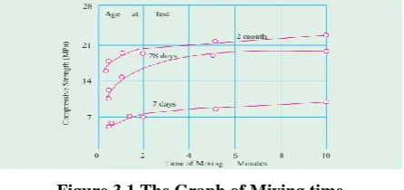
Mixing Time: Concrete mixers are generally designed to run at a speed of 15 to 20 revolutions per minute. For
proper mixing, it is seen that about 25 to 30 revolutions are required in a well-designed mixer. In the site, the
normal tendency is to speed up the outturn of concrete by reducing the mixing time. This results in poor quality
of concrete.
Figure 3.1 The Graph of Mixing time
of view of rate of production of concrete and fuel consumption. Therefore, it is of importance to mix the
concrete for such a duration which will accrue optimum benefit.
It is seen from the experiments that the quality of concrete in terms of compressive strength will increase with
the increase in the time of mixing, but for mixing time beyond two minutes, the improvement in compressive
strength is not very significant. Fig shows the effect of mixing time on strength of concrete. The prepared fresh
concrete are shown in fig. are given below.
Plates- Ready Concrete
Teston concrete
Test on concrete are done in accordance with IS: 516-1959 in two stage of concrete:
1) Testing of fresh concrete or wet concrete, and
2) Testing of hardened concrete
Test on fresh concrete are done to determine its workability. These tests are as follows:
1) Slump test
2) Compacting factor test,
3) Vee bee consistency test
4) Flow table test
Slump test: Slump test is the most commonly used method of measuring consistency of concrete which can be
employed either in laboratory or at site of work. It is not a suitable method for very wet or very dry concrete. It
does not measure all factors contributing to workability, nor is it always representative of the placability of the
concrete. However, it is used conveniently as a control test and gives an indication of the uniformity of concrete
from batch to batch. Repeated batches of the same mix, brought to the same slump, will have the same water
content and water cement ratio; provided the weights of aggregate, cement and admixtures are uniform and
aggregate grading is within acceptable limits. Additional information on workability and quality of concrete can
be obtained by observing the manner in which concrete slumps. Quality of concrete can also be further assessed
by giving a few tapping or blows by tamping rod to the base plate. The deformation shows the characteristics of
concrete with respect to tendency for segregation.
The apparatus for conducting the slump test essentially consists of a metallic mould in the
Form of a frustum of a cone having the internal dimensions as under
: 20 cm
Top diameter :
10 cm
Height : 30 cm
Slump testing
The result of slump test which are conduct in the lab are given below
Slump difference = height of slum apparatus - height of fresh concrete
= 30cm – 25.5cm
= 4.5
The result shows the medium degree of workability of fresh concrete
Curing Methods
Curing method are divided in to 4 categories
1. Water curing 2. Membrane curing 3. Application of heat 4. Miscellaneous
Water curing:
This is by far the best method of curing as it satisfied all the requirements of curing namely. Promotion of
hydration, elimination of shrinking and absorption of the heat of hydration. It is pointed out that even if the
membranes method is adopted, it is desirable that a certain extent of water curing is done before the concrete is
covered with membranes. Water curing can be done in the following ways;
a) Immersion
b) Pounding
c) Spraying or fogging
d) Wet covering
The precast concrete item is normally immersed in curing tanks for a certain duration. Pavement slab, roof slab,
deck slab etc.are covered under water by making small pounds.verticallyretaining wall or plastered surface or
concrete column etc.are cured by spraying water. In some cases, wet covering such as wet gunny bags, hessian
cloth, jute matting, straw etc. are wrapped to vertical surface for keeping the concrete wet. For horizontal
surfaces saw dust, earth or sand are used as wet covering to keep the concrete in wet condition for a longer time
so that the concrete is not unduly dried to prevent hydration. So in my thesis work we use the water curing
pounding system. And after 28 days we check the strength of the bubble deck slab as well as the strength of the
conventional deck slab system.
Testing of the bubble deck slab and the conventional solid slab
The testing of bubble deck slabs as well as the solid deck slab in the shear failure, flexural failure and check the
strength of the slabs on the Universal testing machine
Procedure
1) Adjust the supports along the UTM bed so that they are symmetrically with respect to the length of
2) Place the slab on the knife-edges on the blocks so as to project equally beyond each knife-edge.
See that the load is applied at the centre of the slab.
3) Apply a load and again note the reading.
4)
Go on taking reading applying load in steps each time till you have minimum 6 readings. Find thedeflection in each time by subtracting the initi
al
reading.REFERENCES
Books
[1.] Essentials of BRIDGE ENGINEERING (Six edition) by D.JOHNSON VICTOR Former professor of civil
engineering Indian Institute of technology Madras, Chennai.
Codes
[2.] IS 5640:1970 Method of test for determining aggregates impact value of soft coarse aggregates
[3.] IS 10262:2009 Concrete Mix Proportioning-Guidelines
Technical Reports
[4.] Wang, K., Jansen, D.C., and Shah, S., "Permeability study of cracked concrete," Cement and Concrete
Research, Vol.27, No.3, 1997, pp. 381-393.
[5.] Sergiu Cal in, CiprianAsavoaie and N. Florea, "Issues for achieving an experimental model" Bul. Inst.
Polit. lai, t. LV (LIX), f. 3, 2009.
[6.] Martina Schnellenbach-Held and KarstenPfeffer,"Punching behavior ofbiaxial hollow slabs" Cement and
Concrete Composites, Volume 24,Issue 6, Pages 551-556, December 2002
[7.] SergiuCalin and CiprianAsavoaie, "Method for Bubble deck slabconcrete slab with gaps", The
BuletinulInstitutuluiPolitehnic din lai,LV (LTX), f. 2,2009.
[8.] Sergiu Cal in, C.Mugurel, G.Dascalu, C.Asavoaie, "Computational simulation for concrete slab with
spherical gaps", Proceedings of The 8-th International Symposium, Concepts in Civil Engineering,
Ed.SocietatiiAcademice "Matei-TeiuBotez", 2010, pp. 154-161.
[9.] Oesterle, R.G. et al., Jointless and Integral Abutment Bridges – Summary Report,Final Report to Federal
Highway Administration, Washington D.C., 1999.
Patents
[10.]Tina Lai "Structural behavior of bubble deck slab and their applications to lightweight bridge decks”
M.Tech thesis, MIT, 2009.
Websites
[11.]BubbleDeck voided Flat Slab Solutions- Technical Manual andDocuments, Version: 5, Issue 1,
BubbleDeck UK, White Lodge,Wellington Road, St Savior, JERSEY, C.1., 2008, Available: