R E S E A R C H P A P E R
Open Access
Learning-based active 3D measurement
technique using light field created by video
projectors
Yuki Shiba
1*, Satoshi Ono
1, Ryo Furukawa
2, Shinsaku Hiura
2and Hiroshi Kawasaki
3Abstract
The combination of a pattern projector and a camera is widely used for 3D measurement. To recover shape from a captured image, various kinds of depth cues are extracted from projected patterns in the image, such as disparities from active stereo or blurriness for depth from defocus. Recently, several techniques have been proposed to improve 3D quality using multiple depth cues by installing coded apertures in projectors or by increasing the number of projectors. However, superposition of projected patterns forms a complicated light field in 3D space, which makes the process of analyzing captured images challenging. In this paper, we propose a learning-based technique to extract depth information from such a light field, which includes multiple depth cues. In the learning phase, prior to the 3D measurement of unknown scenes, projected patterns as they appear at various depths are prepared from not only actual images but also ones generated virtually using computer graphics and geometric calibration results. Then, we use principal component analysis (PCA) to extract features of small patches. In the 3D measurement (reconstruction) phase, the same features of patches are extracted from a captured image of a target scene and compared with the learned data. By using the dimensional reduction by feature extraction, an efficient search algorithm, such as an approximated nearest neighbor (ANN), can be used for the matching process. Another important advantage of our learning-based approach is that we can use most known projection patterns without changing the algorithm.
Keywords: Active stereo, Structured light, Depth from defocus, Computational photography, Light filed projection,
Coded aperture, Learning-based reconstruction, Principal component analysis, Approximate nearest neighbor, Belief propagation
1 Introduction
Video projectors are now in a widespread use for vari-ous purposes beyond just image presentation on a white screen. Because of their recent technological progress and cost efficiency, they are also useful for such applications as projection mapping on complicated shapes and 3D recon-struction of objects. Among these, 3D scanning systems using a projector and a camera have been researched for a long time.
Previously, because such a system usually relied on just a single depth cue, 3D shapes were reconstructed by standard stereo imaging, depth from defocus (DfD), or photometric stereo techniques. By using such traditional
*Correspondence:[email protected]
1Kagoshima University, Kagoshima, Japan
Full list of author information is available at the end of the article
methods, it is difficult to incorporate multiple depth cues into a single captured image, which would result in more stable and more accurate depth measurement. Recently, several techniques have been proposed to improve the 3D quality by installing coded apertures into the projectors or by increasing the number of projectors, which would provide multiple depth cues for reconstruction. In the first case, the coded aperture installed in the projector increases depth-dependent information and avoids defo-cus blur. However, since patterns projected on a target surface can be represented by convolution of the aperture and the projection pattern, it is difficult to analyze such convoluted information. In the second case, the number of depth cues is increased by simply using more projec-tors, a technique that is similar to the multi-view stereo technique. However, contrary to a multi-camera system, multiple patterns projected onto the same object’s surface
interfere with each other, making it difficult to separate features. A practical solution is to use a different wave-length (color) for each projector to be able to decompose them as from independent projectors. However, with this method, only three wavelengths (red-green-blue, or RGB) can be used with common (off-the-shelf ) projectors, and crosstalk phenomena between different color channels remains an open problem.
Both the abovementioned techniques can be under-stood as a construction of a unique light field in 3D and extraction of depth cues from a part of it. Because the structure of a light filed composed by multiple projectors is complicated, analysis of such a synthetic light filed in practice is quite difficult. In this paper, instead of sepa-rating a light field from different depth cues, we propose a learning-based technique to extract depth information directly from the light field.
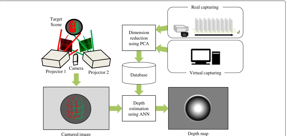
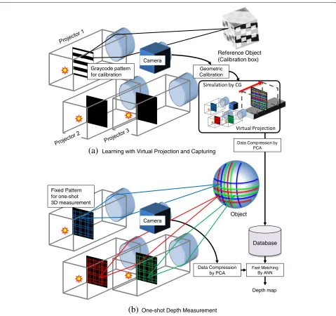
Figure 1 shows the overview of the proposed shape reconstruction technique. The key to our technique is based on the fact that such a projector-sourced light field is locally smooth and consists of similar blocks in 3D space; the multiple projectors project some regular pat-terns that coalesce to form a continuous light field in the space [1,2]. Our solution is to sample a large num-ber of small image areas or patches from the light field and apply a machine learning technique to reduce the size of the dataset as well as shorten the depth calcula-tion time. The method can be divided into two phases: a learning phase and a shape reconstruction phase. In the learning phase, because there is no medium to reflect the light rays in the air, the patterns are invisible and
unobservable, and therefore, we put a planar board in the scene to capture the patterns. Further, we conduct a principal component analysis (PCA) to eliminate redun-dant dimension and thus compact the data. In the shape reconstruction phase, to reduce both the dataset size and a calculation time, we use an approximated nearest neigh-bor (ANN) search algorithm combined with a belief prop-agation (BP) algorithm, which efficiently removes noise thereby increasing robustness and quality in the final output.
The main contributions of this paper are as follows.
1 Multiple depth cues (e.g., disparity and defocus) can be superposed into a single captured image to make depth measurements stable and accurate. Also, multiple projectors can be used simultaneously. Note that the number of the projectors need not be limited to the number of color channels because our
technique is not based on pattern separation approach, which is common in previous techniques. 2 Capturing all possible sample images is not always
necessary; virtually generated images can be used for supervisory signals in the learning phase.
3 Our proposed system can incorporate various feature extraction and learning algorithms. We venture to propose a simple method, which uses PCA and ANN as it does not require hyperparameters except for the number of dimensions, whereas deep learning techniques [3] require many fine-tuned hyperparameters and a long processing time for learning.
Depth map Captured image
d
Virtual capturing Projector 2
Camera Projector 1
Target Scene
Real capturing
Depth estimation using ANN Database Dimension
reduction using PCA
2 Related works
In an active stereo system, a video projector is often used as a light source to measure a wide area in a short period of time, and the history of those techniques was sum-marized in [4]. Such systems usually rely on just a single depth cue, and therefore, 3D shapes are reconstructed by standard stereo imaging, by DfD or by photometric stereo techniques. Recently, several techniques that use multiple depth cues for active stereo systems have been proposed. A method devised by Masuyama et al. relies on both stereo and DfD cues by projecting multiple patterns along the same optical axis but using different focal lengths [5]. However, sharing the same optical axis complicates the system, and overlapping multiple patterns severely lowers the contrast. Zhang et al. proposed a method
for projecting different patterns and successfully recon-structed a high-density depth map by analyzing the cap-tured defocused image set [6]. Achar proposed a method projecting a pattern with different foci to enlarge the pos-sible depth range [7]. However, because those approaches require multiple images for reconstruction, they are com-plicated and have only a limit range of application. Our technique is based on a single image and free from these problems.
Another approach to increase the depth cues using a video projector is to attach a coded aperture mask to the projector. Girod et al. used an asymmetric aperture to distinguish the forward and backward blur for depth from defocus (DfD) [8]. Moreno-Noguer et al. installed a small circular aperture to use the DfD technique [9], and
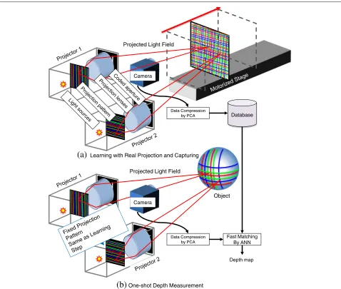
Camera
Database Data Compression
by PCA
Camera
Object
Data Compression by PCA
Fast Matching By ANN
Depth map
(a)
Learning with Real Projection and Capturing(b)
One-shot Depth Measurement Projected Light FieldProjected Light Field
Kawasaki et al. put a coded aperture on a video projec-tor to improve accuracy and density while applying the DfD method [10,11]. However, for all those techniques, depth range is limited and reconstruction is unstable and inaccurate because the analysis of defocus blur is still an unsolved problem and difficult to apply.
Because patterns formed by video projectors construct a synthetic light field, the above techniques can be consid-ered extractions of depth cues from a sampled light field projected onto an object surface. However, as mentioned earlier, because of its complicated nature, only limited research has been done to analyze of a synthetic light field
created by projectors. Kawasaki et al. proposed a tech-nique to capture the entire light field by a special sampling machine [12], but the dataset size proved to be very large and calculation time high. In contrast, we propose two approaches to create a blur-free light field and to recover 3D information using compact data representation and low computational time.
Sagawa et al. proposed a depth measurement method based on a convolutional neural network (CNN) [3]. Although purposes of both Sagawa’s and our methods are the same, such as dimension reduction of patch fea-ture, the approaches of our and Sagawa’s methods are
Reference Object (Calibration box)
Database
Geometric Calibration
Object
Fast Matching By ANN
Depth map
Camera
Data Compression by PCA
Data Compression by PCA
(a)
Learning with Virtual Projection and Capturing Graycode patternfor calibration
Fixed Pattern for one-shot 3D measurement
Camera
(b)
One-shot Depth MeasurementFig. 4Pattern projection with coded aperture for different target depths
totally different, i.e., Sagawa et al. tried to explicitly separate overlapped patches into each projector’s pat-tern and trained a CNN to reduce the effects of color crosstalks caused by using multiple projectors, whereas our method learns to use the overlapping light fields as a whole. Also, the CNN requires many hyperparam-eters and a long processing time for training, whereas our method using PCA does not require hyperparameters (except for specifying the number of dimensions of the
reduced data space), nor a long computational time for learning.
Fanero et al. [13] proposed to use a camera with infrared illumination for close-range human 3D capturing. Their method assume close-range measurement and limited kinds of materials (e.g., limiting to human hands or faces), where illuminated intensity can be a range cue, whereas our method can deal with much wider object classes, object shapes, and working ranges.
Camera and Projector calibration
Sample image synthesis for all depths
PCA for extracting eigenimages from patches of sample images
Capture
Calculate low dimensional representation using basis of eigenimages
Calculate the distances for all the pixels of the captured image
Belief propagation using all costs (distances)
3D reconstruction I. Learning phase II. Reconstruction phase
Virtual system Real system
Capturing image for all depths
3 Overview
3.1 System configuration
The learning-based 3D shape reconstruction method pro-posed in this paper is characterized by integrating multi-ple types of depth cues. Our technique can be applied to various system configurations of active 3D measurement, particularly where conventional analytical reconstruction methods are difficult to apply. Examples of our system configuration are shown in Figs.2and3.
Figure2shows a configuration using a single or multi-ple video projectors incorporating a coded aperture [12]. In this system, both the aperture mask and projected pat-tern involve mutually parallel lines. Figure 4 shows an example of how a projector with a coded aperture con-structs the light field in the space. As the distance from the projector to the target surface changes, the projected patterns change. Because the aperture mask has many small slits, the projector preserves both high-frequency patterns and the total amount of light energy. By pro-jecting a pattern that varies according to the depth, it is possible to perform depth measurements based on depth cues from defocus blur. In theory, if there are multiple projectors, shape can be recovered with depth cues by disparity. However, because in practice, those depth cues are intermixed, common techniques cannot be applied.
Figure 3 shows an example system configuration that consists of one charged coupled device (CCD) camera and multiple common (off-the-shelf ) projectors. In general, it has been necessary to project patterns with different wavelengths in order to separate depth cues after mea-surement. However, because our proposed method has the advantage that single color patterns from multiple projectors can be differentiated by a machine learning approach, simpler 3D shape reconstruction systems are possible without needing different wavelengths.
Fig. 6Extracting image features of sample images
In addition to the example system configuration, Figs.2 and 3 show the processes involved in our proposed method, which has two main stages: the image database learning phase and the depth measurement phase. In the learning phase, the database is constructed from the actual or virtually captured images using data compres-sion. Then, in the measurement phase, a 3D shape of the target scene is reconstructed from a captured image using the database.
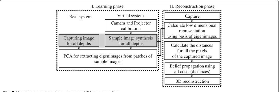
3.2 Algorithm overview
Figure5outlines the algorithm of our proposed method. When constructing an image database in the learning phase, a large number of small image patches are sam-pled from the light field and stored in the database (see Section 4.1). However, this means that the size of the image dataset as sampled from the light field becomes extremely large. In particular, because complicated pro-jection patterns with different types of disparities and defocus effects are projected from multiple projectors, spatial frequency becomes high. For this reason, we pro-pose feature extraction using PCA to reduce the size of the image dataset and thereby shorten the processing time for distance estimation [14,15]. The same process is per-formed not only when constructing the database but also when matching the input image with those already in the database.
Next, distance is estimated by matching each input image patch with image patches already in the database in the depth shape reconstruction phase (Section4.3). Origi-nally, this matching process required full search, and thus, the calculation cost was high. In the proposed method,
Fig. 7Samples of eigenvectors visualized in image format
Table 1The depth cues for the two proposed methods and previous method
Multiple projector Depth cue Learning data Reconstruction
Disparity Defocus ANN PCA
Previous method [12] x Real x
System 1: two projectors equipping a coded aperture Real
System 2: three general video projectors x Simulation
ANN processing is used to perform high-speed match-ing (see Section4.2). Regardless of the projection patterns and/or the number of projectors, learning-based recon-struction processing as described above can perform 3D measurement.
4 Learning-based 3D shape reconstruction 4.1 Database creation
In the learning phase, we capture an image for each depth and build a database consisting of image patches with depths as labels. In order to reduce the size of the samples dataset, we then perform feature extraction based on the eigenimages obtained through PCA. The image patches then are represented by feature vectors and stored in the database.
In the proposed method, image databases are cre-ated from either actual images or virtually captured images. Figure 2a shows an example of a case requir-ing actual image capturrequir-ing. When a coded aperture is installed in a projector, interference between the light source and the lens makes virtual capture of sample images difficult [12]. Therefore, actual image captur-ing is necessary. In this case, patterns from the pro-jector are imaged on a white planar board placed on a motorized stage, are captured, and are stored in the database.
When using off-the-shelf projectors that do not have a coded aperture or similar modification, the virtual image capture approach can be applied. Figure 3a shows an example of a configuration and procedure for creating a pattern using multiple projectors, which can be simulated
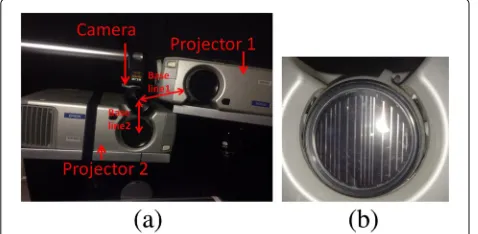
Fig. 8Actual optical system.aSetup with two projectors.bCoded aperture installed on the right projector lens
easily by computer graphics (CG). In practice, external parameters for each projector and a camera as well as internal parameters of them are acquired by geometric calibration of the real system. Then, a pattern is simulta-neously projected from all virtual projectors onto a virtual planar board, and sample images are captured by a virtual camera while moving the planar board.
4.2 Low-dimensional representation by PCA
When the proposed method estimates pixel depth, an image patch around the pixel is compared with the pre-viously obtained sample images. By repeating this pro-cess for all pixels in the captured image, the 3D shape of the target object is reconstructed. As this is a time-consuming process, in practice, we use PCA to obtain low-dimensional feature representation (also known as eigenspace representation) of the image patches to reduce the calculation time for data matching.
PCA has long been used in computer vision studies to reduce the dimensionality of image data. Examples of PCA has been used for such processing including facial image recognition or analysis to represent or separate changes of illumination or facial expressions [14,15], object recog-nition across various images captured from different 3D
Fig. 10Eigenimages created by PCA. Eigenimages with high contribution ratios are arranged in order from the top left
viewpoints [16], and fast image matching achieved by dimension reduction of raw image data vectors [17].
Figure6shows the process of extracting features from projected patterns. To apply PCA, we first collect the training set from the sample images to calculate the eigenspace of the dataset. In the proposed method, the sample images are obtained in the calibration process, where the images of the fronto-parallel planes are cap-tured by an actual setup of a projector camera system or are generated by a virtual projector simulation. From the sample images, image patches of the same size are extracted.
The image patches are first represented as column vec-tors ofp1,p2,· · ·,pNby simple rasterization. If the image patches areMbyMpixels, the dimension of the column vectors isM2. Here, we useL = M2for simplicity. The average image patch is calculated byp¯ = N1 Nk=1pk, and deviation from the average data byqk = pk− ¯p. A set of orthonormal bases for representingqk can be calculated using PCA.
In normal PCA, eigenvectorsu1,u2,· · ·,uLof theL×L
covariance matrix:
C= 1 N
N
k=1
qkqk =A A, (1)
where A =[q1 q2 · · · qN], are used for the orthogonal basis set. However, in computer vision problems, often N < L, and then, we can use eigenvectorsv1,v2,· · ·,vN
of the N ×N matrixL = A Afor forming the basis set to save the computational cost of eigenvector calcu-lation [14]. The basis vectors, then, can be calculated by ui = Nk=1(vi)k (qk)fori = 1,· · ·,N, where(vi)k is the
kth element of vectorvi.
From the obtained basis, the representation of a new image patch r is (w1 w2 · · · wN), where wi = ui (r− ¯p). Let eigenvectors v1,v2,· · ·,vN be sorted by
the descending order of the associated eigenvalues. Then, u1,u2,· · ·,uN are aligned in the order of optimal
repre-sentation of the training set{q1,· · ·,qN}for minimizing the sum of errors ofl2norm. Thus, if the image patchris similar to the training set,(w1w2· · · wL)whereL≤N,
is a goodL’-dimensional representation ofr. The process to determine the basis set using PCA can be regarded as a process of learning the image features for representing the pattern training set.
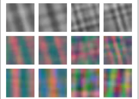
Figure7shows the eigenvector basis for different pat-tern projections in the system shown in Fig.3a. The top row images are extracted from grid patterns created by a single projector, the middle row images are from grid patterns made using two projectors, and the bottom row images are from grid patterns made using three projec-tors. These results show that the basis represents the features of the training image set for different types of light field.
0 2 4 6 8 10 12 14
250 300 350 400 450 500 550
]
m
m[
E
S
M
R
Depth [mm]
Kinect2 Random dot stereo
PCA+ANN (1 proj. 12x12 window) PCA+ANN (1 proj. 16x16 window)
PCA+ANN (2 projs. 12x12 window) PCA+ANN (2 projs. 16x16 window)
0 0.5 1 1.5 2 2.5 3
no texture checker dappled milk drop newspaper wooden
]
m
m[
E
S
M
R
kinect
NCC
ANN (Hand-craft, 20D)
Proposed (PCA, 20D)
Proposed (PCA, 48D)
Fig. 12RMSE of planes with texture. Manual decode means a hand-crafted feature proposed in [12]. Our method performed better than the previous technique except Kinect
In the database construction step, we calculate the low-dimensional (L’-D) representations for the sample patch images. In the 3D measurement step, we calculate theL’ -D vectors for the image patches around each pixel. These patches are matched with the images sampled for each depth in theL’-D vector space.
4.3 Efficient depth estimation by ANN and MRF
In the depth estimation phase, we use the proposed tech-nique to capture a target object as shown in Figs.2b or 3b. Then, we convert the input images to low-dimensional representations by calculating the coefficients of eigenim-ages. Next, we search for the sample image patch most similar to each input image pixel. Although the proposed method requires only 10 to 40 dimensions, computational cost to find such patches for all the depths is still high. To reduce the calculation cost, we use an ANN search [18], where input data are stored in a k-d tree structure, which reduces the processing time with minimal sacrifice in accuracy.
Although a reconstructed 3D shape inevitably contains some amount of noise cased by wrong depth estimation, such wrong depths are efficiently removed or corrected by a Markov random field (MRF) approach. For MRF, cost volume is usually required; however, ANN originally returns just a single cost for maximum similarity. Because top 10% depth candidate values ordered by similarity includes the correct depth with a 90% probability based on our survey, we modified ANN to output that top 10% with cost (the reciprocal of similarity). We use BP [19] to solve the MRF.
5 Experiments
In order to verify the effectiveness of the proposed method, we implemented two kinds of systems. The first
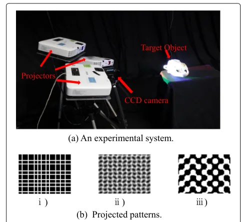
system uses one camera and two projectors fitted with coded apertures. The second system uses three unal-tered (off-the-shelf ) projectors with one camera. The depth cues for each system are summarized in Table1. Experimental results using each system are described sequentially in the following Sections 5.1 and 5.2, respectively.
5.1 System 1 using projectors fitted with coded apertures Generally, the shallow depth of field of an off-the-shelf projector limits the depth measurement range of a pro-jector camera system. Kawasaki et al. proposed a method to install a coded aperture to extend the depth range [12]. In the proposed system, we extend the technique by increasing the number of projectors, as shown in Fig.8a. With this setup, because the optical phenomenon is complicated, we construct a database from the learn-ing phase by capturlearn-ing actual images. Figure 9 shows the actually observed patterns generated using a projec-tor with a coded slit pattern aperture installed and those created by a normal (off-the-shelf ) projector with a cir-cular aperture for comparison. As shown in the figure, high-frequency patterns for all ranges are preserved by the coded aperture, whereas patterns are rapidly blurred out by the circular aperture.
Fig. 13Textures used in the experiments.aChecker pattern.b
(a) Input image (b) Result by NCC
(c) Result by the proposed method (PCA+ANN, 12D)
(d) Result by [12] with hand-crafted features (12D)
(e) Result by the proposed method (PCA+ANN, 48D)
(f) Result by [12] with hand-crafted features (48D)
Fig. 14Reconstruction results (depth images) of the real object using system 1.aInput image.bResult by NCC.cResult by the proposed method (PCA+ANN, 12D).dResult by [12] with hand-crafted features (12D).eResult by the proposed method (PCA+ANN, 48D).fResult by [12] with hand-crafted features (48D)
5.1.1 Eigenimages created by PCA
We installed one of this projector and a camera1 and acquired images for depths in the 250 to 550 mm range at sampling intervals of 0.5 mm. Because of the limitation of the length of the motorized stage, we put a close-up lens to change the scale as to be 1/3 of real length. As a result of a dimensional compression by PCA, the eigenimages obtained are as in Fig.10, showing vertical, horizontal, and combined vertical-horizontal patterns.
5.1.2 Accuracy evaluation
In order to verify the depth estimation accuracy of the proposed method, we conducted a depth measurement
(a) NCC (48D) (b) Proposed (PCA+ANN, 48D)
Fig. 15Reconstruction results (point clouds) of the real object using system 1.aNCC (48D).bProposed (PCA+ANN, 48D)
Fig. 16System 2 implementation and projected patterns.a
Experimental system with a camera and a video projector.bSeveral patterns for one-shot scan. (i) Random grids, (ii) Wave grids [20]. (iii) Wave grids2 [21]
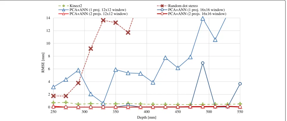
experiment on a flat board. In this experiment, vertical and horizontal patterns were projected at focusing dis-tances of 250 mm and 350 mm, respectively. The target screen is placed on the motorized stage and moved to a depth of 250 to 550 mm while capturing at 10 mm inter-vals. The depth value was estimated using the proposed method. In addition to the case using two projectors, the case using only one projector that projects the vertical pat-tern was also tested. The matching window sizes were set to 16×16 or 12×12 pixels, and the number of feature dimensions was reduced to 12 by PCA. Note that the win-dow size and the number of feature dimensions were set
(a) hand (b) buffalo skull
(c) boots (d) monkey
Fig. 17Objects used in the experiments.aHand.bBuffalo skull.c
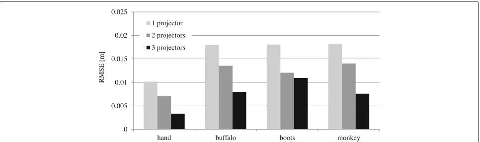
0 0.005 0.01 0.015 0.02 0.025
hand buffalo boots monkey
]
m[
E
S
M
R
1 projector
2 projectors
3 projectors
Fig. 18Comparison on RMSE with varying the number of projectors. The larger number of projectors results in better accuracy
relatively small to verify the effectiveness of increasing the depth cue, i.e., the number of projectors. Other two meth-ods, Microsoft Kinect 2 and an active stereo method using a random dot pattern, were also evaluated for comparison. Figure11shows the the root mean square error (RMSE) of the estimated depth value. The graph demonstrates that, even with smaller window, the proposed method using two projectors could recover the correct depth for all the tested ranges with almost the same accuracy as Kinect 22. Accuracy of the case using one projector was deteriorated when using smaller matching window; even when using larger window, its accuracy was degraded at depths of 480 mm and 550 mm.
5.1.3 Evaluation of learning-based feature extraction In the next experiment, the robustness against the tex-tures on a target object was evaluated; a vertical pattern was projected onto a flat board at a focusing distance of 250 mm. For comparison, the shapes were recon-structed by NCC without dimension reduction, by NCC with dimension reduction by hand-crafted feature [12], and by using Microsoft Kinect. In the experiments, the size of the image patch was set to 24×24 pixels for all techniques. Therefore, the length of the feature vector before dimensional compression is 24×24×3 =1, 728. Then, it is reduced to 20 or 48 dimensions by PCA and hand-crafted feature technique. The experimental results are shown in Fig.12. The proposed method, combining
Fig. 19Eigenimages created by PCA. Eigenimages with a high contribution rate are arranged in order from the top left
PCA and ANN, achieved a lower RMSE than the hand-crafted feature technique, although it is inferior to NCC.
The same experiment was also carried out on different textures shown in Fig.13, and the experimental results are shown in Fig.12. When we measured these variously textured objects, reconstruction accuracy was equal to or higher than NCC. In addition, some textures (e.g., dap-pled, milk drop, and newspaper) show that the accuracy improves when more dimensions are used. Furthermore, if a checkered or dappled pattern image was measured, the proposed technique can perform with almost the same accuracy as Kinect, whereas it gets worse if the texture is strong (e.g., milk drop, newspaper, or wood board).
5.1.4 Evaluation by 3D object reconstruction
Next, we reconstructed the shape of a real object. As with the previous section, we compared our reconstruction method with NCC and hand-crafted feature [12]. The experimental results are shown as depth images in Fig.14
Fig. 21Reconstruction results of textured and curved surface object with wave pattern.aInput.bDepth map (PCA).cDepth map (NCC)
and as point clouds in Fig. 15. Hand-crafted feature provides good reconstruction results for 48 dimensions. However, when the reduction is performed for 12 dimen-sions, the reconstruction quality is significantly degraded. On the other hand, the proposed method can estimate stable depths even when the feature dimensions are compressed to 12 dimensions because of the efficient dimensional reduction by PCA.
5.2 System 2 using multiple projectors
This system consists of three video projectors and a single CCD camera. Because three projectors are off-the-shelf products and just a static pattern is projected from each device, virtual data creation by CG simulation is possible, as shown in Fig.16a.
Fig. 22Reconstruction results of textured and curved surface object with wave pattern 2 proposed by [21].aInput.bdepth map (PCA).c
Depth map (NCC)
Our proposed technique does not depend on projec-tion patterns. To demonstrate this advantage, we used several well-known patterns (Fig. 16) for one-shot scans (spatial encoding patterns) in our experiment: a random grid pattern, a wave grid pattern [20], and a pattern (wave 2) that is commonly used for single color one-shot scans [21].
5.2.1 Effect of increasing the number of projectors
We first tested the effectiveness of increasing the num-ber of projectors while using NCC and the unicolor wave pattern, which has relatively high reconstruction accuracy. The unicolor wave pattern was used in each projector. Red and green patterns were assigned to two projectors; in the case of three projectors, blue was added to the two-projector setup. In the learning phase, we used CG simulation to create sample images in the 400 to 700 mm range at sampling intervals of 1 mm. For NCC, when com-paring a captured image to sample images, the window size was 32×32 for the coarse process and 24×24 for the fine process.
In this experiment, four objects with arbitrary shape and texture were measured and reconstructed: a pair of boots, a buffalo skull (buffalo), a hand, and a monkey doll (Fig.17). Measurement results using a conventional gray-code method were referenced as ground truth. Figure18 shows the results. As the number of projectors increased, the accuracy improved for all four objects. This is because more projectors could make more complicated patterns, which produce better depth cue information.
5.2.2 Reconstruction of textured and curved surface objects with various patterns
To evaluate the dimension reduction of feature values using PCA, the following two methods were compared: NCC without dimension reduction and the proposed method involving dimension reduction by PCA. In this
(a) (b) (c) (d)
Fig. 23Point clouds and reconstructed shapes of textured and curved surface objects with wave pattern 2 proposed by [21].aPoint cloud (ANN).bPoint cloud (NCC).cReconstructed shape (ANN).d
0 0.002 0.004 0.006 0.008 0.01
hand buffalo boots monkey
]
m[
E
S
M
R
Grid (NCC) Grid (PCA)
Wave (NCC) Wave (PCA)
Wave 2 (NCC) Wave 2 (PCA)
Fig. 24Comparison on RMSE with varying reconstruction method (NCC and PCA) and projection pattern. Note that accuracy is almost the same between NCC and PCA (our method) where the data size and computational cost of PCA are much lower than NCC
experiment, three projectors were used. For the proposed method with PCA, as the same condition with the experi-ment of Section5.1, the patch size was set to 24×24. For the PCA, principal components up to the 30th level were applied.
As a result of dimensional compression by PCA, eigen-images were obtained (Fig. 19). A combination of line patterns was observed in the images.
Depth maps and the reconstruction results are shown in Figs.20,21, and22, and point clouds and 3D surfaces reconstructed from wave 2 pattern are shown in Fig.23. We found that the proposed method could reconstruct object shapes with curved surfaces and non-uniform texture using any tested projection patterns. However, we observed some individual pattern tendencies, such as our PCA-based reconstruction method was affected by the complicated curve and texture while using the grid pattern (Fig.20).
5.2.3 Precision evaluation
We validated the 3D reconstruction precision of NCC and the proposed PCA-based method by comparing the results of the experiments described in Section 5.2.2. Figure24shows the comparison results on RMSE, which show no significant difference for RMSE between NCC and PCA methods. This means that the dimension reduc-tion by PCA did not degrade the reconstrucreduc-tion accuracy. Next, we discuss the difference between CNN and PCA for dimension reduction by reviewing the results of earlier work [3] using three of the same objects (hand, buffalo, and boots). In that earlier work, RMSE values for the CNN-based method for the three objects were 1.03, 1.41, and 1.22, and those for NCC were 1.22, 1.74, and 1.553, respectively. This is naturally understood that CNN out-performs other methods if the condition is the same in recent vast studies. Since the feature extraction processes
are almost the same for both Sagawa’s and our techniques, if CNN is used for our method for feature extraction pro-cess, it is expected to produce better results. Incorporating deep learning techniques into the proposed method is our important future work; however, we believe that it does not reduce the contribution of our paper.
5.2.4 Processing time for reconstruction
The results comparing the reconstruction time (Fig.25) clearly shows that PCA reduced the reconstruction time4, despite the combination of a coarse-to-fine approach for NCC. This is because PCA requires just 30 dimen-sional features, whereas NCC requires 24× 24× 3 = 1, 728 dimensions. The computational complexity of reconstruction is O(n) for NCC andO(logn) for PCA, wherenis the number of sample images.
6 Conclusions
We propose a learning-based 3D reconstruction tech-nique for active stereo systems. With our techtech-nique, a
0 10 20 30 40 50
NCC PCA
]s
[
e
mit
n
oit
c
urt
s
n
oc
e
R
Coarse search
Fine search
light field is formed by attaching a coded aperture to the projector and/or by using multiple projectors that project arbitrary patterns and are in arbitrary poses. The resulting light field forms patterns on 3D surfaces with rich depth cue information. Because these cues are not easily extracted by existing analysis, we propose a learning-based approach that can be applied universally for various arbitrary types of image cues. The dataset of sample images for different depths is generated by real (actual) scan or by CG simulation. To realize efficient matching to sample data when processing the depth mea-surement, the dimensionality of the raw data of image patches in the sample image dataset is reduced by PCA so that the the image patches in the captured image can be compared with the sample image dataset in low-dimensional space. Experimental results prove that our technique is stable irrespective of target object materials, sensor noise, and projection patterns. In the future, deep learning techniques and real-time parallel processing will be applied.
Endnotes
1In this experiment, one projector was used because
using two projectors increases the robustness of the pro-posed method, making it difficult to assess the robustness against the object textures.
2Note that the scale was converted to 1/3 of the real
length [12].
3 The accuracy of NCC was better in that earlier work
because images were captured while changing the planar board angle in the learning phase, but the same was not done in our experiment.
4The reconstruction was performed on a personal
com-puter equipping Intel Core i7 3770 (3.4 GHz, 4 core) and 32 GB RAM.
Acknowledgements
Not applicable.
Authors’ contributions
All the authors were responsible for designing the method, writing the code, implementing the systems, performing the experiments, and writing and modifying this manuscript. All authors read and approved the final manuscript.
Funding
This work was supported in part by JSPS KAKENHI Grant Nos. 15H02758, 15H02779, and 16H02849; MIC SCOPE 171507010; and MSR CORE12.
Availability of data and materials
For requirements, please contact the authors via e-mail.
Competing interests
The authors declare that they have no competing interests.
Author details
1Kagoshima University, Kagoshima, Japan.2Hiroshima City University, Hiroshima, Japan.3Kyushu University, Fukuoka, Japan.
Received: 6 April 2018 Accepted: 27 May 2019
References
1. Jurik J, Jones A, Bolas M, Debevec P (2011) Prototyping a light field display involving direct observation of a video projector array. In: Computer Vision and Pattern Recognition Workshops (CVPRW), 2011 IEEE Computer Society Conference On. IEEE, Colorado Springs. pp 15–20
2. Visentini-Scarzanella M, Hirukawa T, Kawasaki H, Furukawa R, Hiura S (2015) Two plane volumetric display for simultaneous independent images at multiple depths. In: Pacific-Rim Symposium on Image and Video Technology. Springer-Verlag, New York. pp 113–126
3. Sagawa R, Furukawa R, Matsumoto A, Kawasaki H (2017) Learning-based feature extraction for active 3d scan with reducing color crosstalk of multiple pattern projections. In: 2017 IEEE International Conference on Robotics and Automation (ICRA). IEEE, Singapore. pp 5074–5080 4. Salvi J, Pages J, Batlle J (2004) Pattern codification strategies in structured
light systems. Pattern Recog 37(4):827–849
5. Masuyama H, Kawasaki H, Furukawa R (2014) Depth from projector’s defocus based on multiple focus pattern projection. IPSJ Trans Comput Vision Appl 6:88–92
6. Zhang L, Nayar S (2006) Projection defocus analysis for scene capture and image display. ACM Transactions on Graphics (TOG), New York Vol. 25. pp 907–915
7. Achar S, Narasimhan SG (2014) Multi focus structured light for recovering scene shape and global illumination. In: European Conference on Computer Vision. Springer, Cham. pp 205–219
8. Girod B, Scherock S (1990) Depth from defocus of structured light. In: 1989 Advances in Intelligent Robotics Systems Conference. International Society for Optics and Photonics, Philadelphia. pp 209–215
9. Nayar SK, Watanabe M, Noguchi M (1996) Real-time focus range sensor. IEEE Trans Pattern Anal Mach Intell 18(12):1186–1198
10. Kawasaki H, Horita Y, Masuyama H, Ono S, Kimura M, Takane Y (2013) Optimized aperture for estimating depth from projector’s defocus. In: 3D Vision-3DV 2013, 2013 International Conference On. IEEE, Seattle. pp 135–142
11. Kawasaki H, Horita Y, Morinaga H, Matugano Y, Ono S, Kimura M, Takane Y (2012) Structured light with coded aperture for wide range 3D
measurement. In: IEEE Conference on Image Processing (ICIP). Orlando, IEEE
12. Kawasaki H, Ono S, Horita Y, Shiba Y, Furukawa R, Hiura S (2015) Active one-shot scan for wide depth range using a light field projector based on coded aperture. In: Proceedings of the IEEE International Conference on Computer Vision. IEEE, Santiago. pp 3568–3576
13. Fanello SR, Keskin C, Izadi S, Kohli P, Kim D, Sweeney D, Criminisi A, Shotton J, Kang SB, Paek T (2014) Learning to be a depth camera for close-range human capture and interaction. ACM Trans Graph 33(4):86–18611 14. Turk M, Pentland A (1991) Eigenfaces for recognition. J Cogn Neurosci
3(1):71–86
15. Bowyer KW, Chang K, Flynn P (2006) A survey of approaches and challenges in 3D and multi-modal 3D + 2D face recognition. Comput Vision Image Underst 101(1):1–15
16. Murase H, Nayar SK (1995) Visual learning and recognition of 3-d objects from appearance. Int J Comput Vision 14(1):5–24
17. Uenohara M, Kanade T (1997) Use of Fourier and Karhunen-Loeve decomposition for fast pattern matching with a large set of templates. IEEE Trans Pattern Anal Mach Intell 19(8):891–898
18. Muja M, Lowe DG (2009) Fast approximate nearest neighbors with automatic algorithm configuration. In: International Conference on Computer Vision Theory and Application. INSTICC. pp 331–340 19. Felzenszwalb P, Huttenlocher D (2006) Efficient belief propagation for
early vision. IJCV. Washington, 70:41–54
20. Sagawa R, Sakashita K, Kasuya N, Kawasaki H, Furukawa R, Yagi Y (2012) Grid-based active stereo with single-colored wave pattern for dense one-shot 3D scan. In: Proc. 2012 Second Joint 3DIM/3DPVT Conference. IEEE, Zurich. pp 363–370
21. Vuylsteke P, Oosterlinck A (1990) Range image acquisition with a single binary-encoded light pattern. IEEE Trans PAMI 12(2):148–164
Publisher’s Note
![Fig. 12 RMSE of planes with texture. Manual decode means a hand-crafted feature proposed in [12]](https://thumb-us.123doks.com/thumbv2/123dok_us/842898.1582024/9.595.59.541.86.263/rmse-planes-texture-manual-decode-crafted-feature-proposed.webp)