Genemutant: Test Suite Adequacy Check For
Path Coverage Testing Based On Mutating Test
Suite Using Genetic Algorithm
Dr Namita Gupta
Computer Science and Engineering Department, Maharaja Agrasen Institute of Technology, Rohini, Delhi, India Email: [email protected]
ABSTRACT: Code coverage is a measure used to describe the degree to which the source code of a program is tested by a particular test suite. A program with high code coverage has been more thoroughly tested and has a lower chance of containing software bugs than a program with low code coverage. Many different metrics can be used to calculate code coverage like statement coverage, decision coverage, condition coverage, path coverage etc. Path coverage ensures that every independent path in the program should be executed at least once by the give test suite. The proposed technique check the adequacy of given test suite and design new test cases (if required) by mutating the existing test cases, for path coverage testing based on genetic algorithm using XNOR fitness function.
Keywords :Genetic algorithm, Mutation testing, Path testing
1.
I
NTRODUCTIONSoftware testing is done to detect the faults in the given source code. Test cases are developed to test the software. Static and dynamic testing techniques are available to test the software. Static testing techniques analyze the target software without actually executing the code to identify the errors. Dynamic testing executes the code using given test cases to detect presence of faults. Mutation testing also called Mutation analy-sis or Program mutation is the testing technique, used to eva-luate the quality of existing software test suite and design new test cases. Mutation testing involves modifying a program's source code. Each mutated version is called a mutant and tests detect and reject mutants if the behavior of the original version of the source code differs from the mutant. This is called killing the mutant. Test suites are measured by the per-centage of mutants that they kill. New tests can be designed to kill additional mutants. The purpose is to help the tester devel-op effective tests or locate weaknesses in the given test data used for the program or in sections of the code that are sel-dom or never accessed during execution. Mutants are created based on mutation. Many mutation operators have been ex-plored by researchers. Here are some examples of mutation operators for imperative languages:
Statement deletion.
Replace boolean expression with true or false.
Replace arithmetic operator with another, e.g. + with *, - and /.
Replace relational operator with another, e.g. > with >=, == and <=.
Replace variable with another variable declared in the same scope (variable types must be compatible).
Adequacy of the given test suite is evaluated through mutation score defined as:
mutation score
= number of mutants killed / total number of mutants (1)
Although powerful, Mutation Testing is complicated and time-consuming to perform without an automated tool. Efficiency of the technique depends on the number of mutants created. Few mutants may miss some areas of programs to test if the corresponding test case is missing in the give test suite. Too
many mutants increase overhead and technique complexity. To check the adequacy of test suite efficiently and to design new test cases, a new technique is proposed. Instead of mod-ifying the source code to create new mutants, test case is mu-tated i.e., an input value of the single variable in the given test case is changed to satisfy the given condition at the predicate node. The proposed algorithm is based on Path testing. The objective of path testing is to ensure that each possible inde-pendent path through the program is executed at least once. An independent program path is one that traverses at least one new edge in the flow graph. In program terms, this means exercising one or more new conditions. Both the true and false branches of all conditions must be executed. The starting point for path testing is a program flow graph. A flow graph consists of nodes representing decisions and edges showing flow of control. The flow graph is constructed by replacing program control statements by equivalent diagrams. Each branch in a conditional statement (if-then-else or case) is shown as a sep-arate path. An arrow looping back to the condition node de-notes a loop. Each statement in the program graph is represented as a separate node where the node number cor-responds to the line number in the program. To reduce the complexity of program graph, control flow graph is created where sequential nodes are replaced by single node. Control graph contain following different types of nodes:
i. Starting Node / Initial Node
ii. Terminating Node / Stop Node / End Node iii. Sequential Node
iv. Predicate/Decision Node v. Junction Node
1.1GENETIC ALGORITHM
Genetic algorithm starts with initial pool of chromosomes and attempts to improve the set by evolution [1][2]. It typically has five parts:
1) a representation of a chromosome - . A chromosome can be a binary string or a more elaborate data structure. 2) an initial pool of chromosomes - It can be randomly
pro-duced or manually created.
3) a fitness function - The fitness function measures the sui-tability of a chromosome to meet a specified objective i.e., a chromosome is fitter if it corresponds to greater coverage.
4) a selection function - The selection function decides which chromosomes will participate in the evolution stage of the genetic algorithm made up by the crossover and mutation operators.
5) a crossover operator and a mutation operator - The cros-sover operator exchanges genes from two chromosomes and creates two new chromosomes. The mutation opera-tor changes a gene in a chromosome and creates one new chromosome.
Basic algorithm for a Genetic Algorithm [3] follows well-defined steps:
initialize (population) evaluate (population)
while (stopping condition not satisfied) do {
selection (population) crossover (population) mutate (population) evaluate (population) }
The algorithm will iterate until the population has evolved to form a solution to the problem (sufficient test cases), or until a maximum number of iterations have taken place (suggesting that a solution is not going to be found given the resources available). In this paper, we discussed the proposed GENEmu-tant algorithm for path testing. To evaluate the effectiveness of given test suite and identify the section of codes not covered by the given test cases, proposed method applies genetic al-gorithm based on f(XNOR) fitness function.
2.
RELATED
WORK
Many researchers have proposed the application of genetic algorithm in different areas of software testing. Riccardo and Langdon [4] described two forms of crossover, one-point cros-sover and the new strict one-point croscros-sover. Strict one-point crossover, behaves exactly like one-point crossover except that the crossover point can be located only in the parts of the two trees which have exactly the same structure (i.e. the same functions in the nodes encountered traversing the trees from the root node). Sean and Lee [5] showed that crossover is better over mutation given the right parameter settings (primar-ily larger population sizes). It is observed that mutation is more successful in smaller populations, and crossover is more suc-cessful in larger populations. Leonardo [6] proposed a fitness function that incorporates the three basic conditions required by a test case to kill a given mutant of some subject program. Method uses genetic algorithm to search for test cases that satisfy the reachability condition. The proposed fitness function has been implemented, together with a genetic algorithm and
posed algorithm is discussed; case studies based on pro-posed method are discussed in section 4. We conclude in sec-tion 5.
3.
PROPOSED
ALGORITHM
-
GENE
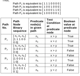
MUTANTFor the given source code, cyclomatic complexity technique is used to find all possible independent paths. Test suite is then used to identify the paths covered by the given test. Each in-dependent path is represented as a binary sequence showing 1 if node is present in the path and 0 if node is absent. Thus, each path Pi is represented as a binary sequence containing
nodes [ n1 n2…… nk ], where k is the total no. of nodes in flow
graph. Likewise, for each given test case Tj, identify the binary
sequence of nodes appearing in the path traversed by it and represent the same as [ n1 n2 …… nk]. Next step is to select
the test case for each independent path from the given test pool and design new test case(s) for non-traversed path(s). Genetic algorithm is applied to select/design the test cases. Steps for the genetic algorithm are:
1. Fitness Function
Compute Rji= ij [Tj XNOR Pi] (2)
such that,
function
(3)
i.e., ( 0 XNOR 1 ) is 0 ( 1 XNOR 0 ) is 0 ( 0 XNOR 0 ) is 1 ( 1 XNOR 1 ) is 1
A test case Tj is fitted for path Pi if it contains all 1’s in
resul-tant row after applying between them. To avoid
re-dundancy among test cases and minimize the number of test cases, the following rules should be followed:
Rule 1 : If more than one test case traverses the same path, then randomly select single test case for final test suite.
Rule 2 : If a test case traverses more than two independent paths, then preference should be given to such test case over others while selecting the test case for Rule 1.
2. Selection
The selection procedure selects individuals of the current popu-lation for development of the next generation. Various alterna-tive methods exist but all follow the idea that the fittest have a greater chance of survival. Selection chooses the chromo-somes to be recombined and mutated out of this initial popula-tion. [n.gupta] Identify the non-zero predicate nodes np in the
non-traversed path nodes sequence. If, the immediate next node nx is not a predicate node then,
If nx = (4)
If nx is a predicate node then,
If nx = (5)
Check the condition at the predicate nodes in the non-traversed path. Match within the selected chromosomes (test case) that satisfy the give condition(s). Test cases that match maximum number of Boolean values of predicate nodes in the non-traversed path are selected to have their solution passed onto the next generation.
3. Crossover
Selected chromosomes are crossover to create next genera-tion. It combines two chromosomes (parents) to produce a new chromosome (child). The new chromosome takes the best characteristics from each of the parents. One point, two points, uniform, arithmetic are few crossover operators [9]. In GENEmutant algorithm, arithmetic operator is used. Arithmetic operator linearly combines two parent chromosome vectors to produce two new children according to the following equa-tions:
Child1 = a * parent1 + (1-a) * parent2 (6)
Child2 = (1-a) * parent1 + a * parent2 (7)
where a is a random weighting factor between 0 and 1, cho-sen before each crossover operation. Take a = 0.5 initially and then increase or decrease its value based on the results ob-tained.
4. Mutation
Even though the crossover produces a large range of solutions, it may lead the evaluation function towards local maxima. The purpose of mutation in Genetic algorithm is preserving and introducing diversity. For different genome types, different mu-tation types are available [9] like flip bit, Gaussian, insert, swap, inversion, scramble mutation etc. In GENEmutant algorithm, if the predicate condition is not satisfied by the selected somes after multiple crossover iterations, then existing chromo-some is mutated based on the predicate condition.
4.
CASE
STUDY
EXAMPLE 1
Consider the source code given below start int isabsequal(int x, int y)
{
1 if (x==y) 2 return 1; 3 else if (x==-4) 4 return -1;
5 Else
6 return 0; stop }
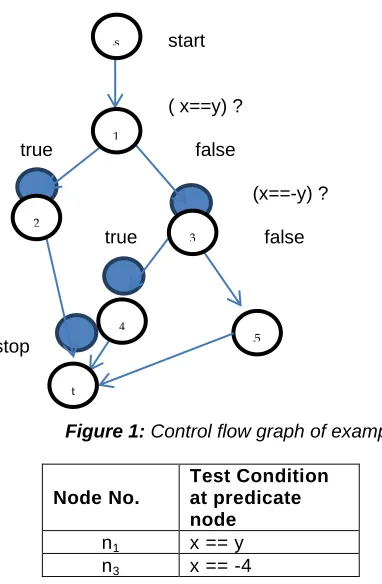
Given source code is represented as control flow graph shown as figure 1 below.
start
( x==y) ?
true false
(x==-y) ?
true false
stop
Figure 1: Control flow graph of example 1
Node No.
Test Condition at predicate node
n1 x == y
n3 x == -4
Table 1 : Shows the predicate nodes in the flow graph and the
condition at each predicate node
On applying cyclomatic complexity technique,
No. of independent paths = no of predicate nodes + 1 = 2+1 = 3
Independent paths are
(Path 01)P1= [ start n1 n2 stop ]
(Path 02)P2= [ start n1 n3 n4 stop]
(Path 03)P3= [ start n1 n3 n5 n6 Stop ]
There is a total of 6 nodes from n1 to n6 (excluding the Start
and Stop node). Each path is represented as a binary se-quence of nodes [ n1 n2 n3 n4 n5 n6 ] showing 1 against
tra-versed node and 0 against untratra-versed node in corresponding path.
Thus,
Path P1 is equivalent to [ 1 1 0 0 0 0 ]
Path P2 is equivalent to [ 1 0 1 1 0 0 ]
Path P3 is equivalent to [ 1 0 1 0 1 1 ]
Path No.
Path Node Binary sequence
Predicate node(s) in given path
Test Condition at predicate node
Boolean value at predicate node
P1
[n1 n2]
[ 1 1 0 0 0 0 ]
n1 x == y True
P2
[ n1 n3 n4 ]
[ 1 0 1 1 0 0 ]
n1 x == y False
n3 x == -4 True
P3
[n1 n3 n5 n6
]
[ 1 0 1 0 1 1 ]
n1 x == y False
n3 x == -4 False
Table 2: Shows the details about predicate nodes appearing
in each independent path
Given input test cases T1: {x=5, y=3}
T2: {x=9, y=9}
Test case No.
Test Case
Predicate node(s) in flow graph
Test Condition at
predicate node
Boolean value at predicate
node
T1
{x=5, y=3}
n1 x == y False
n3 x == -4 False
T2
{x=9, y=9}
n1 x == y True
n3 x == -4 False
Table 3: Shows the Boolean value of predicate nodes for the
given test case(s)
Each test case Tj, is represented as a binary sequence of
nodes appearing in the path traversed by it. Thus, each test case is represented as a binary sequence containing [n1 n2 n3
n4 n5] by traversing the flow graph (Figure 1) and using the
information given in table 1 and 3.
Test T1 is equivalent to [ 1 0 1 0 1 1 ]
Test T2 is equivalent to [ 1 1 0 0 0 0 ]
Compute Rji= ij [Tj XNOR Pi ], i.e.,
T1XNOR P1=[ 1 0 1 0 1 1 ] XNOR [ 1 1 0 0 0 0 ]= [ 1 0 0 1 0 0 ]
T1XNOR P2=[ 1 0 1 0 1 1 ] XNOR [ 1 0 1 1 0 0 ]= [ 1 1 1 0 0 0 ]
T1 XNOR P3=[ 1 0 1 0 1 1 ] XNOR [ 1 0 1 0 1 1 ] = [ 1 1 1 1 11 ]
T2 XNOR P1= [1 1 0 0 0 0 ] XNOR [ 1 1 0 0 0 0 ] = [ 1 1 1 1 11 ]
T2 XNOR P2=[ 1 1 0 0 0 0 ] XNOR [ 1 0 1 1 0 0 ]= [ 1 0 0 0 1 1 ]
T2 XNOR P3=[ 1 1 0 0 0 0 ] XNOR [ 1 0 1 0 1 1 ]= [ 1 0 0 1 0 0 ]
Now, a test case Tj is selected corresponding to path Pi that
contains all 1’s in resultant row.
5
5 5 5
3
5
4
5
t
5
2
5
So, in final test suite, test case T1 is selected corresponding to path P3 and test caseT2 is selected corresponding to path P1. It is analyzed that there is no test case corresponding to path P2. Next step is to design new test case from the given test suite. Genetic algorithm is applied to design the new test case for path P2. Steps for the genetic algorithm are:
1. Selection
Test cases are selected from the given population (test suite) that matches maximum number of boolean values of predi-cate nodes in the non-traversed path P2.
Using Tables 2 and 3, following observation is recorded:
Table 4: Shows test case matching to missed path
As test case T1 matches one test condition of P2 non-traversed
path, so only test case T1 is selected for designing new test
case for path P2. Now, next step is to mutate the test case so
that it will satisfy all the test conditions of non-traversed path.
2. Mutation
Test case T1{x=5, y=3} matches the required predicate
condi-tion at node n1(x==y), but violates the predicate condition at
node n3 (x==-4). If the predicate condition is not satisfied by
the selected chromosomes, then existing chromosome is mu-tated based on the predicate condition. Hence chromosome T1
is mutated as {x=-4, y=3}. Now both the conditions at the pre-dicate nodes are satisfied and mutated test case successfully traverse path P2. Hence, three test cases T1 : {x=5, y=3} for
path P3, T2 : {x=9, y=9} for path P1 and new test case T3 :
{x=-4, y=3} for path P2 are required to test all the independent
paths of the above problem.
EXAMPLE 2
Consider the source code given below start int product (int exp)
{ 1 int i = exp; 2 int j = 1;
3 while ( i > 0 ) { 4 j = 2*j;
a. 5 i--; } 5 return j; stop }
start
(i>0) ?
true
false
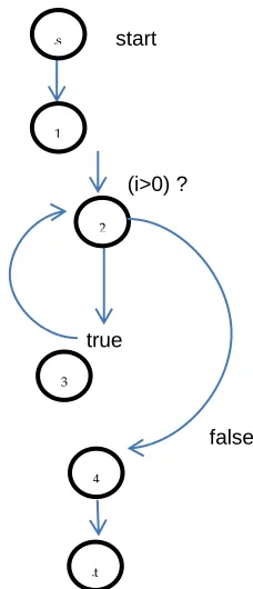
Figure 2: Control flow graph of example 2
Node No.
Test Condition at predicate node
n2 i > 0 (initially i = exp)
Table 5 : Shows the predicate node(s) in the flow graph and
the condition at predicate node
On applying cyclomatic complexity technique, No. of independent paths
= no of predicate nodes + 1 = 1+1 = 2
Independent paths are
(Path 01) P1= [ start 1 2 4 stop ]
(Path 02) P2= [ start 1 2 3 ((2 3)) 4 stop]
((2 3)) shows n iterations of loop.
There is a total of 4 nodes from n1 to n4 (excluding the Start
and Stop node). Each path is represented as a binary se-quence of nodes [ n1 n2 n3 n4 ] showing 1 against traversed
node and 0 against untraversed node in corresponding path. Thus,
Path P1 is equivalent to [ 1 1 0 1 ]
Path P2 is equivalent to [ 1 1 1 1 ]
Path No.
Path Node Binary sequence
Predicate node(s) in given path
Test Condition at predicate node
Boolean value at predicate node
P1
[ n1 n2 n4 ]
[1 1 0 1] n1
i > 0 (initially i =
exp)
False
P2
[ n1 n2 n3 n4]
[1 1 1 1] n1
i > 0 (initially i =
exp)
True
Table 6: Shows the details about predicate nodes appearing
in each independent path
3
5
5t 5 5
4
5
2
5
1 5 5 5s 5 5
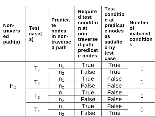
Non-traversed
path(s) Test case(s)
Predicate nodes in
non-traversed
path
Required test conditio n at
non-traverse d path predicat e nodes
Test condition
at predicate nodes as satisfied by test
case
Number of matched conditions
P2
T1
n1 False False 1
n3 True False
T2
n1 False True
0
Given input test cases T1: {exp=0}
T2: {exp=1}
T3: {exp=-5}
Each test case Tj, is represented as a binary sequence of
nodes appearing in the path traversed by it. Thus, each test case is represented as a binary sequence containing [n1 n2 n3
n4 ].
Test case No.
Test Case
Predicate node(s) in flow graph
Test Condition at
predicate node
Boolean value at predicate node
T1 {exp=0} n1
i > 0 (initially i =
exp)
False
T2 {exp=1} n1
i > 0 (initially i =
exp)
True
T3 {exp=-5} n1
i > 0 (initially i =
exp)
False
Table 7: Shows the Boolean value of predicate nodes for the
given test case(s)
Each test case Tj, is represented as a binary sequence of
nodes appearing in the path traversed by it. Thus, each test case is represented as a binary sequence containing [n1 n2 n3
n4] by traversing the flow graph (Figure 2) and using the
infor-mation given in table 5 and 7.
Test T1 is equivalent to [ 1 1 0 1 ]
Test T2 is equivalent to [ 1 1 1 1 ]
Test T3 is equivalent to [ 1 1 0 1 ]
Compute Rji= ij [Tj XNOR Pi ], i.e.,
T1XNOR P1=[ 1 1 0 1 ] XNOR [ 1 1 0 1 ] = [ 1 1 1 1 ]
T1XNOR P2= [ 1 1 0 1 ] XNOR [ 1 1 1 1 ] = [ 1 1 0 1 ]
T2 XNOR P1= [ 1 1 1 1 ]XNOR [ 1 1 0 1 ] = [ 1 1 0 1 ]
T2 XNOR P2=[ 1 1 1 1 ] XNOR [ 1 1 1 1 ] = [ 1 1 1 1 ]
T3 XNOR P1=[ 1 1 0 1 ] XNOR [ 1 1 0 1 ] = [ 1 1 1 1 ]
T3 XNOR P2= [ 1 1 0 1 ] XNOR [ 1 1 1 1 ] = [ 1 1 0 1 ]
Now, a test case Tj is selected corresponding to path Pi that
contains all 1’s in resultant row. So, in final test suite, test case T1 and T3 is selected corresponding to path P1 and test caseT2 is selected corresponding to path P2. It is analyzed that there is two test cases corresponding to path P1. According to Rule 1 either of the two test cases T1 or T3 is selected in final test suite to minimize the size of final test suite. Hence, two test cases T1 : {exp=0} for path P1, T2 : {exp=1} for path P2 are
re-quired to test all the independent paths of the above problem.
EXAMPLE 3
Consider the source code given below start int largest(int x, int y, int z)
{ 1 if (x > y) 2 if (x > z)
3 return x;
4 else
5 return z; 6 else if (y > z) 7 return y;
8 else
9 return z;
stop }
Given source code is represented as control flow graph as shown in figure 3.
start
(x>y) ?
false true
(y>z)? (x>z) ?
false true false true
stop
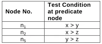
Figure 3: Control flow graph of example 3
Node No.
Test Condition at predicate node
n1 x > y
n2 x > z
n5 y > z
Table 8: Shows the predicate nodes in the flow graph and the
condition at each predicate node
On applying cyclomatic complexity technique,
No. of independent paths = no of predicate nodes + 1 = 3+1 = 4
Independent paths are
(Path 01)P1= [ start n1 n2 n3 stop ]
(Path 02)P2= [ start n1 n2 n4 stop]
(Path 03)P3= [ start n1 n5 n6 Stop ]
(Path 04)P4= [ start n1 n5 n7 Stop ]
There is a total of 7 nodes from n1 to n7 (excluding the Start
and Stop node). Each path is represented as a binary se-quence of nodes [ n1 n2 n3 n4 n5 n6 n7] showing 1 against
tra-t
5
53
5
5
2
5
4
5
5
5
1 5 5 5s 5 5
6
5
7
versed node and 0 against untraversed node in corresponding path.
Thus,
Path P1 is equivalent to [ 1 1 1 0 0 0 0 ]
Path P2 is equivalent to [ 1 0 0 1 0 0 0 ]
Path P3 is equivalent to [ 1 0 0 0 1 1 0 ]
Path P4 is equivalent to [ 1 0 0 0 0 0 1 ]
Path No.
Path Node Binary sequence
Predicate node(s) in given path
Test Condition at
predicate node
Boolean value at predicate node
P1
[ n1 n2 n3 ]
[1 1 1 0 0 0 0]
n1 x > y True
n2 x > z True
P2
[ n1 n2 n4 ]
[1 0 0 1 0 0 0]
n1 x > y True
n2 x > z False
P3
[ n1 n5 n6 ]
[1 0 0 0 1 1 0]
n1 x > y False
n5 y > z True
P4
[ n1 n5 n7 ]
[1 0 0 0 1 0 1]
n1 x > y False
n5 y > z False
Table 9: Shows the details about predicate nodes appearing
in each independent path
Given input test cases T1: {x=5, y=2, z=4}
T2: {x=2, y=7, z=9}
T3: {x=2, y=7, z=4}
T4: {x=2, y=7, z=1}
Test case No.
Test Case
Predicate node(s) in flow graph
Test Condition at
predicate node
Boolean value at predicate node
T1
{x=5, y=2, z=4}
n1 x > y True
n2 x > z True
n5 y > z False
T2
{x=2, y=7, z=9}
n1 x > y False
n2 x > z False
n5 y > z False
T3
{x=2, y=7, z=4}
n1 x > y False
n2 x > z False
n5 y > z True
T4
{x=2, y=7, z=1}
n1 x > y False
n2 x > z True
n5 y > z True
Table 10: Shows the Boolean value of predicate nodes for the
given test case(s)
Each test case Tj, is represented as a binary sequence of
nodes appearing in the path traversed by it. Thus, each test case is represented as a binary sequence containing [n1 n2 n3
n4 n5 n6 n7] by traversing the flow graph (Figure 3) and using
the information given in table 8 and 10.
Test T1 is equivalent to [ 1 1 1 0 1 0 1 ]
Test T2 is equivalent to [ 1 0 0 0 1 0 1 ]
Test T3 is equivalent to [ 1 0 0 0 1 1 0 ]
Test T4 is equivalent to [ 1 0 0 0 1 1 0 ]
Compute Rji= ij [Tj XNOR Pi ], i.e.,
T1XNOR P1
=[1 1 1 0 0 0 0] XNOR [1 1 1 0 0 0 0]=[ 1 1 1 1 1 1 1 ]
T1XNOR P2
= [1 1 1 0 0 0 0] XNOR [1 0 0 1 0 0 0]=[ 1 0 0 0 1 1 1 ]
T1 XNOR P3
= [1 1 1 0 0 0 0] XNOR [1 0 0 0 1 1 0] = [ 1 0 0 1 0 0 1 ]
T1 XNOR P4
= [1 1 1 0 0 0 0] XNOR [1 0 0 0 1 0 1] = [ 1 0 0 1 0 1 0 ]
T2 XNOR P1
= [1 0 0 0 1 0 1] XNOR [1 1 1 0 0 0 0] = [ 1 1 1 1 1 1 1 ]
T2 XNOR P2
= [1 0 0 0 1 0 1] XNOR [1 0 0 1 0 0 0] = [ 1 1 1 0 0 1 0 ]
T2 XNOR P3
= [1 0 0 0 1 0 1] XNOR [1 0 0 0 1 1 0] = [ 1 1 1 1 1 0 0 ]
T2 XNOR P4
= [1 0 0 0 1 0 1] XNOR [1 0 0 0 1 0 1] = [ 1 1 1 1 1 1 1 ]
T3 XNOR P1
= [1 0 0 0 1 1 0] XNOR [1 1 1 0 0 0 0] = [ 1 0 0 1 0 0 1]
T3 XNOR P2
= [1 0 0 0 1 1 0] XNOR [1 0 0 1 0 0 0] = [ 1 1 1 0 0 0 1]
T3 XNOR P3
= [1 0 0 0 1 1 0] XNOR [1 0 0 0 1 1 0]= [ 1 1 1 1 1 1 1 ]
T3 XNOR P4
= [1 0 0 0 1 1 0] XNOR [1 0 0 0 1 0 1] = [ 1 1 1 1 1 0 0]
T4 XNOR P1
= [1 0 0 0 1 1 0] XNOR [1 1 1 0 0 0 0] = [ 1 0 0 1 0 0 1]
T4 XNOR P2
= [1 0 0 0 1 1 0] XNOR [1 0 0 1 0 0 0] = [ 1 1 1 0 0 0 1]
T4 XNOR P3
= [1 0 0 0 1 1 0] XNOR [1 0 0 0 1 1 0] = [ 1 1 1 1 1 1 1]
T4 XNOR P4
= [1 0 0 0 1 1 0] XNOR [1 0 0 0 1 0 1] = [ 1 1 1 1 1 0 0 ]
Now, a test case Tj is selected corresponding to path Pi that
P2. Genetic algorithm is applied to design the new test case for path P2. Steps for the genetic algorithm are:
1. Selection
Test cases are selected from the given population (test suite) that matches maximum number of boolean values of predi-cate nodes in the non-traversed path P2.
Using Tables 2 and 3, following observation is recorded:
Table 11: Shows test case matching to missed path
As test cases T1 , T2 and T3 matches single test condition each
of P2 non-traversed path, so T1 , T2 and T3 test cases are
se-lected for designing new test case for path P2. Now, next step
is to mutate the test cases so that mutant test case will satisfy all the test conditions of non-traversed path .
2. Fitness function
Compute Ri= i [Tj XNOR P2 ] , i=1,2,3
Select the test case Ti corresponding to path P2 that
contains all 1’s in resultant row.
3. CrossOver
Test case T1{ x=5, y=2, z=4} matches the required predicate
condition (true) at node n1 (x > y), test case T2{ x=2, y=7, z=9}
and T3 {x=2, y=7, z=4}matches the required predicate
condi-tion (false) at node n2 (x > z). Since both the predicate
condi-tions n1 and n2 are not being satisfied by any single selected
chromosome, hence existing chromosomes T1 and T2 or T3
are crossover to create new chromosome satisfying both the required predicate conditions.
T1: {x=5, y=2, z=4}
T2: {x=2, y=7, z=9}
Predicate condition at node n1 =(x > y) and at node n2 =(x >
z). Since gene x is common in both conditions, it is selected for single arithmetic crossover. Initially, α is chosen as 0.5 randomly.
Child1 is {α.x1 + [1- α].x2, y1, z1}
Child2 is {[1- α]. x1 + α.x2, y2, z2}
Child1 is {x=3.5,y=2,z=4}
Child2 is {x=3.5,y=7,z=9}
Non-traversed
path(s)
Test case(s)
Predicate nodes in
non-traversed
path
Required test condition
at non-traversed
path predicate
nodes
Test condition
at predicate nodes as satisfied by test
case
Number of matched conditions
P2
child1
n1 True True 2
n2 False False
child2
n1 True False 1
n2 False False
Table 12: Shows new test case matching missed path
Since both the predicate conditions n1 and n2 are being
satis-fied by single child chromosome child1 , so test case child1 is selected corresponding to path P2 in final test suite. Hence, test cases T1 : {x=5, y=2, z=4} for path P1, T2 : {x=2, y=7, z=9}
for path P4 , T3 : { x=2, y=7, z=4} for path P3 and new test case
child1 : { x=3.5,y=2,z=4} for path P2 are required to test all the
independent paths of the above problem.
5.
CONCLUSION
AND
FUTURE
SCOPE
In the paper, Genetic algorithm has been used to search the input domain of the subject program for suitable test cases. Guidance is provided by the fitness function which assigns a non-negative value to each candidate input test case. A test case that matches the maximum predicate nodes in the path is selected for the next generation. But, there are certain limita-tions of the proposed method.
Testing all the paths does not mean that all bugs in a program are found. Bugs may be due to missing statements in the code, so there are no paths to ex-ecute.
Some bugs are related to the order in which code segments are executed.
Also it is practically impossible to test all program paths (e.g., loops).
Nested conditions in the path are handled in simplified way.
In future, efforts will be made to overcome the above men-tioned limitations and hence improve the proposed algorithm. Also more case studies containing complex source code will be considered to measure the efficiency of the proposed me-thod.
R
EFERENCES[1] N.K. Gupta and M.K. Rohil, “Using Genetic Algorithm For Unit Testing Of Object Oriented Software”, Pro-ceedings of the International Conference on Emerging Trends in Engineering and Technology, 16-18 July 2008, pp. 308-313,.
[2] M. Mitchell, An Introduction to Genetic Algorithms, MIT press, 1996.
[3] Praveen Ranjan Srivastava and Tai-hoon Kim, “Appli-cation of Genetic Algorithm in Software Testing”, In-ternational Journal of Software Engineering and Its Applications , vol. 3, no. 4, October 2009, pp. 87-95.
Non-travers ed path(s)
Test case( s)
Predica te nodes in non-traverse d path
Require d test conditio n at non-traverse d path predicat e nodes
Test conditio n at predicat e nodes as satisfie d by test case
Number of matched condition s
P2
T1
n1 True True
1 n2 False True
T2
n1 True False
1 n2 False False
T3
n1 True False 1
n2 False False
T4
n1 True False
[4] RICCARDO POLI AND W.B. LANGDON, “GENETIC P
RO-GRAMMING WITH ONE-POINT CROSSOVER AND POINT M
U-TATION”,SOFT COMPUTING IN ENGINEERING DESIGN AND
MANUFACTURING, 1997, PP.180-189.
[5] Sean Luke and Lee Spector, “A Revised Comparison of Crossover and Mutation in Genetic Programming”, Proceedings of the Second Annual Conference on Genetic Programming 1997, 1998, pp. 240-248.
[6] Leonardo Bottaci, “A Genetic Algorithm Fitness Func-tion for MutaFunc-tion Testing”, Proceedings of the first In-ternational Workshop on Software Engineering using Metaheuristic Innovative Algorithms, Toronto, Ontario, Canada, May 2001.
[7] Tzung-pei Hong , Hong-shung Wang , Wen-yang Lin and Wen-yuan Lee, “Evolution of appropriate cros-sover and mutation operators in a genetic process”, Applied Intelligence, Vol. 16, 2002, pp. 7-17.
[8] MARIA CLÁUDIA FIGUEIREDO PEREIRA EMER, AND SILVIA
REGINA VERGILIO,“GPTEST:ATESTING TOOL BASED ON
GENETIC PROGRAMMING”,PROCEEDINGS OF THE GENETIC
AND EVOLUTIONARY COMPUTATION CONFERENCE
(GEC-CO2002),SEPTEMBER 2002, PP.1343-1350.
[9] Wen-Yang Lin, Wen-Yung Lee and Tzung-Pei Hong, “Adapting Crossover and Mutation Rates in Genetic Algorithms”, Journal Of Information Science And En-gineering, Vol. 19, 2003, pp. 889-903.
[10] Abdelaziz M. Khamis, Moheb R. Girgis and Ahmed S. Ghiduk, “Automatic Software Test Data Generation for Spanning Sets Coverage Using Genetic Algo-rithms”, Computing and Informatics, vol. 26, no. 4, 2007, pp. 383–401.
[11] LAWRENCE BEADLE AND COLIN G JOHNSON, “S
EMANTI-CALLY DRIVEN MUTATION IN GENETIC PROGRAMMING”,
PROCEEDINGS OF THE IEEE CONGRESS ON E
VOLUTIO-NARY COMPUTATION (CEC2009),2009, PP.1336-1342.
[12] WILLIAM B.LANGDON,MARK HARMAN AND YUE JIA,“M
UL-TI OBJECTIVE HIGHER ORDER MUTATION TESTING WITH
GENETIC PROGRAMMING”, TESTING: ACADEMIC AND I
N-DUSTRIAL CONFERENCE - PRACTICE AND RESEARCH
TECHNIQUES,2009(TAICPART'09. ),4-6SEPT.2009,
PP.,21-29.
[13] WANG JUN , ZHUANG YAN AND JIANYUN CHEN, “TEST
CASE PRIORITIZATION TECHNIQUE BASED ON GENETIC
ALGORITHM”,PROCEEDINGS OF THE INTERNATIONAL C
ON-FERENCE ON INTERNET COMPUTING &INFORMATION S
ER-VICES (ICICIS),17-18SEPT.2011, PP.173–175.
[14] PRENAL B. NIRPAL AND K.V.KALE, “USING GENETIC A
L-GORITHM FOR AUTOMATED EFFICIENT SOFTWARE TEST
CASE GENERATION FOR PATH TESTING”, INTERNATIONAL
JOURNAL OF ADVANCED NETWORKING AND APPLICATIONS,
VOL.2, NO.6,2011, PP.911-915.
[15] TIMO KÖTZING,ANDREW M. SUTTON, FRANK NEUMANN
AND UNA-MAY O’REILLY,“THE MAX PROBLEM REVISITED:
THE IMPORTANCE OF MUTATION IN GENETIC P
ROGRAM-MING”, PROCEEDINGSOF THE GENETIC AND
EVOLUTIO-NARY COMPUTATION (GECCO’12), JULY 7–11,2012, PP.
1333-1340.