A Study of Temperature Effects on Car Coated
Substrate in Laser Paint Removal
*Mohammad Khairul Azhar Abdul Razab
1,2, Mohamad Suhaimi Jaafar
2, Azhar Abdul Rahman
21. Faculty of Earth Sciences, Universiti Malaysia Kelantan Jeli Campus, Locked Bag No. 100, 17600 Jeli, Kelantan, Malaysia.
2. School of Physics, Universiti Sains Malaysia Main Campus, 11800 Minden, Penang, Malaysia.
Abstract--
Cynosure Cynergy Pulse Nd:YAG laser was used to remove the painted material of 54 car coated substrate samples A, B and C by manipulating the laser fluence energy (F), pulse width (PW), repetition rate (RR) and beam size (BS). Alicona IFM G4 was used to analyze irradiated crater depths and obtained the optical surface micrograph which provides a pattern of graphical illustration of the removal process. Average temperature (ΔTAV) of car metal substrate was determined
during the laser paint removal process by using TC 6621 thermocouple. The maximum ΔTAV (0C) reached were 30.36 and
34.89 with BS 3 mm and 5 mm for sample A, 30.25 and 32.6 with BS 3 mm and 5 mm for sample B whereas 28.16 and 33.15 with BS 3 mm and 5 mm for sample C.
Index Term--
Laser paint removal, Average temperature, Nd:YAG laser, Alicona IFM G4, Car coated substrate.
1. INTRODUCTION
Nowadays, chemical based strippers and grit blasting are the core techniques practiced by Malaysian automotive industry for car repaint. However, neither of these techniques is ideal as both resulting in environmental imbalance due to the generation of a large amount of waste and the process is unfavourable due to high cost especially labour cost [1, 2]. To overcome this problem, laser based paint removal process is found to offer these advantages. The use of laser technology to remove paint layers from a surface has been under development for many years with a variety of lasers, paints and substrates were considered [3]. This superior characteristic has proved to be successful in cleaning industry of polymers, rubber tire moulds, large mirrors, artworks and historical heritage pieces, semiconductor and many more [4, 5]. However, the information of laser cleaning techniques in automotive industry is less discussed as well as their temperature effects and heat transfer on car coating system and metal substrates.
Pulse Nd:YAG laser in infra red (IR) region tends to vibrates and excites free electrons within the coatings and metal substrate which leads to dissipate the laser energy into heat in a short time [6]. Thus, energy absorbed during laser processing material is mostly transformed to heat [7]. Thermal effects in restricted laser ablation is known as heat affected zone (HAZ) [8]. HAZ resulted in a remaining fraction of directly absorbed laser energy on irradiated target during laser ablation mechanism [9]. HAZ is minimal in short laser interaction due to fully absorption of laser energy by painted
material, hence the laser ablation is considered to finish before the heat diffusion starts to occur [8].
Rapid vaporization or thermal stress in paint spallation occurred if the energy of laser beam absorbed is high enough and exceeds thermal threshold of paint adhesion [8]. Significant vaporization observed above the threshold fluence is corresponding to the critical temperature reached for paint layers start to ablate [10]. During the process, heat transfer is considered to contribute in paint ablation and spallation as long as the paint layers is not totally removed [11]. For paint material which has low thermal conductivity, the thermal effect is presented by thermal confinement regime as shown in Equation 1 [10].
LT = Eq. 1
Where LT is thermal diffusion length, D is the thermal diffusivity of irradiated material and τp is pulse duration. From the Equation 1, LT is directly proportional to τp. Thus, application of long pulse duration laser beam was considered to give major influenced to the thermal diffusion length in thermal confinement regime of painted material [10, 12, 13].
Metal substrate damage during paint removal is mainly due to thermal effects induced strain and stress [14]. Thermal effects on metal substrate is critical when the heat is considered to directly dissipate through the metal surface since the entire paint layer has been removed [11]. Directly exposure to high temperature gradients in metal substrate may cause material cracking, depletion of certain material components, thermal stress, ductility deterioration and fatigue life extension effects [6, 14, 15].
2. EXPERIMENTAL
In this study, 54 rectangular shapes of car coated substrate samples were acquired from three types of car models A, B and C. Samples A and B were acquired from two national car model made in the year of 2008 and 2000 with the coating system were orange metallic acrylic and black metallic acrylic, whereas samples C was obtained from an imported car model made in the year of 1992 with the coating system was green solid (non-metallic) acrylic paint and never repaints. The paint thickness was determined by using CEM DT-156 Paint Coating Thickness Gauge Tester F/NF Probe and ranged from 92 – 134 μm, 196 – 450 μm, 219 – 283 μm for substrate samples A, B and C, respectively.
International Journal of Engineering & Technology IJET-IJENS Vol:14 No:02 40
irradiations. The F was increased with 10 J/cm2 for each shoot and PW, RR and BS were manipulated as listed in the Table I.
Table I
Laser parameters considered for 3 mm and 5 mm BS with varies in F, PW and RR.
Sample number
Number of irradiation
BS (mm)
F (J/cm2)
PW (ms)
RR (Hz)
1 10 3 210 - 300 100 1.0
2 10 3 210 - 300 200 1.0
3 10 3 210 - 300 300 1.0
4 10 3 210 - 300 100 1.5
5 10 3 210 - 300 200 1.5
6 10 3 210 - 300 300 1.5
7 10 3 210 - 300 100 2.0
8 10 3 210 - 300 200 2.0
9 10 3 210 - 300 300 2.0
10 10 5 150 - 240 100 1.0
11 10 5 150 - 240 200 1.0
12 10 5 150 - 240 300 1.0
13 10 5 150 - 240 100 1.5
14 10 5 150 - 240 200 1.5
15 10 5 150 - 240 300 1.5
16 10 5 60 - 150 100 2.0
17 10 5 60 - 150 200 2.0
18 10 5 60 - 150 300 2.0
Note: Maximum F for 3 mm BS is 300 J/cm2 for all laser parameters. Meanwhile the maximum F for 5 mm BS is 240 J/cm2 set-up with RR 1.0 and 1.5 Hz whereas 150 J/cm2 set-up with RR 2.0 Hz.
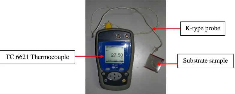
TC 6621 thermocouple was used to measure the metal substrate temperature during laser irradiation. This device consists of K-type probe and was connected to the back of the metal substrate as shown in Figure 1. It has very high reading accuracy which is ± 0.01 °C resolutions. TC 6621 thermocouple was used to determine the metal substrate temperature before, during and after of each laser irradiation. Back side of the metal substrate samples was cleaned and swapped with soft tissue paper to ensure no foreign matters or particulate contaminants existed. This condition ensured the optimum conductivity between the metal substrate to the thermocouple probe for effective temperature measurements.
Initial temperature reading was recorded prior proceed to the first laser irradiation. During laser irradiation, the highest temperature reading was recorded. Second laser irradiation was then restarted on the same substrate sample after the temperature reading reduced to 24 °C. This condition ensured the substrate sample as well as the laser source was cooling down for the next thermal assessments. Thus, the initial, highest and based temperatures (Tbase = 24 °C) were recorded for each irradiation on a certain substrate sample considered.
Fig. 1. Tc 6621 thermocouple and K-type probe detector used to measure the temperature changes on metal substrate during laser paint removal process.
Prior start the experiment, each substrate sample considered was hold by using a sample holder and the laser source to the target distance was fixed at 5 cm. The experimental set-up for this experiment was shown in Figure 2.
K-type probe
Fig. 2. Experimental set-up of Tc 6621 thermocouple for metal substrate temperature measurements during laser paint removal was done in a closed wood box.
Alicona IFM G4 was used to obtain the optical surface micrograph which provides a pattern of graphical illustration between crater surface level and top coating surface level with precise vertical measurement of the irradiated crater depth [16]. Thus, the thermal effects on the painted material of selected crater depth can be easily analyzed. For this study, the selected crater depth considered was the maximum temperature reached, Tmax with its highest F for each type of substrate samples A, B and C as shown in Figure 9, 10 and 11, respectively.
3. RESULTS AND DISCUSSIONS
The results were sorted into 3 main group types of samples A, B and C as shown in Figures 3 - 8. The average of
temperature changes, ΔTAV was determined for each laser parameters applied on the sample substrate A, B and C by using the Equation 2 and was represented in Table II.
ΔTAV = Σ ΔT / nshots Eq. 2
Where ΔTAV (0C) is the average of temperature changes measured on a metal substrate sample, Σ ΔT (0C) is the total of temperature changes for nshots measured from temperature base, Tbase (0C) whereas nshots is the number of laser irradiation obtained on a substrate sample. Tbase is the temperature measured prior initiated each laser irradiation and was fixed at 24 0C.
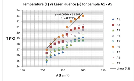
Fig. 3. Increasing of metal substrate temperature, ΔT (0C) with increasing of F for sample A1 – A9. The highest ΔT
AV (0C) was obtained on sample A6 with BS 3
y = 0.0696x + 12.603 R² = 0.9713
24 25 26 27 28 29 30 31 32 33 34
150 200 250 300 350
T (
0C)
F
(J cm
-2)
Temperature (T) vs Laser Fluence (
F
) for Sample A1 - A9
A1
A2
A3
A4
A5
A6
A7
A8
A9
Linear (A6)
Laser source
TC 6621
Thermocouple
Substrate
sample
International Journal of Engineering & Technology IJET-IJENS Vol:14 No:02 42
Fig. 4. Increasing of metal substrate temperature, ΔT (0C) with increasing of F for sample A10 – A18. The highest ΔT
AV (0C) was obtained on sample A15 with
BS 5 mm. Meanwhile, the highest temperature reached, Tmax (0C) was obtained at 40 °C with PW 300 ms, RR 1.5 Hz, BS 5 mm and F 240 J/cm2 for sample A15
on crater depth number 10.
Tmax = 40 0 C
y = 0.1011x + 15.166 R² = 0.9695
24 26 28 30 32 34 36 38 40 42
0 50 100 150 200 250 300
T (
0C)
F
(J cm
-2)
Temperature (T) vs Laser Fluence (
F
) for Sample A10 - A18
A10
A11
A12
A13
A14
A15
A16
A17
A18
Linear (A15)
y = 0.0678x + 12.972 R² = 0.9602
24 26 28 30 32 34 36
150 200 250 300 350
T (
0C)
F
(J cm
-2)
Temperature (T) vs Laser Fluence (
F
) for Sample B1 - B9
B1
B2
B3
B4
B5
B6
B7
B8
B9
Fig. 5. Increasing of metal substrate temperature, ΔT (0C) with increasing of F for sample B1 – B9. The highest ΔTAV (0C) was obtained on sample B6 with BS 3
mm.
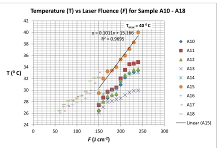
Fig. 6. Increasing of metal substrate temperature, ΔT (0C) with increasing of F for sample B10 – B18. The highest ΔTAV (0C) was obtained on sample B12 with
BS 5 mm. Meanwhile, the highest temperature reached, Tmax (0C) was obtained at 38.25 °C with PW 200 ms, RR 1.5 Hz, BS 5 mm and F 240 J/cm2 for sample
B14 on crater depth number 10.
Fig. 7. Increasing of metal substrate temperature, ΔT (0C) with increasing of F for sample C1 – C9. The highest ΔT
AV (0C) was obtained on sample C1 with BS 3
mm.
Tmax = 38.25 0 C
y = 0.0662x + 19.695 R² = 0.9111
24 26 28 30 32 34 36 38 40
0 50 100 150 200 250 300
T (
0C)
F
(J cm
-2)
Temperature (T) vs Laser Fluence (
F
) for Sample B10 - B18
B10
B11
B12
B13
B14
B15
B16
B17
B18
Linear (B12)
y = 0.0529x + 14.655 R² = 0.9285
24 25 26 27 28 29 30 31
150 200 250 300 350
T (
0C)
F
(J cm
-2)
Temperature (T) vs Laser Fluence (
F
) for Sample C1 - C9
C1
C2
C3
C4
C5
C6
C7
C8
C9
International Journal of Engineering & Technology IJET-IJENS Vol:14 No:02 44
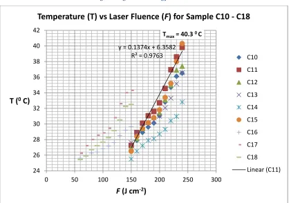
Fig. 8. Increasing of metal substrate temperature, ΔT (0C) with increasing of F for sample C10 – C18. The highest ΔTAV (0C) was obtained on sample C11 with
BS 5 mm. Meanwhile, the highest temperature reached, Tmax (0C) was obtained at 40.3 °C with PW 300 ms, RR 1.5 Hz, BS 5 mm and F 240 J/cm2 for sample C15
on crater depth number 10. Table II
Summarize of ΔTAV and Tmax (0C) for substrate samples A1 – A18, B1 – B18 and C1 – C18.
Sample n
shots Tbase (0C) ΔTmin (0C) ΔTmax (0C) Σ ΔT (0C) ΔTAv (0C)
A1 10 24 24.8 29.15 272.4 27.24
A2 10 24 26.35 30.95 291.3 29.13
A3 10 24 25.2 28.75 273.4 27.34
A4 10 24 26.4 30.5 285.25 28.53
A5 10 24 25.7 28.55 275.6 27.56
A6 10 24 26.95 33 303.6 30.36
A7 10 24 27.2 31.4 297.5 29.75
A8 10 24 25.8 31.5 289.8 28.98
A9 10 24 26.2 29.6 279.35 27.94
A10 10 24 26.5 33.4 303.75 30.38
A11 10 24 27.4 34.85 315.8 31.58
A12 10 24 26.5 33.65 306.6 30.66
A13 10 24 26.1 29.95 284.8 28.48
A14 10 24 27.6 33.1 309.5 30.95
A15 10 24 29.5 40 348.85 34.89
A16 10 24 26.5 30.1 282.3 28.23
A17 10 24 26 33.1 289.5 28.95
A18 10 24 26.4 32.2 293.65 29.37
B1 10 24 24.9 27.57 265.57 26.56
B2 10 24 26.25 30.45 288.05 28.81
Tmax = 40.3 0 C
y = 0.1374x + 6.3582 R² = 0.9763
24 26 28 30 32 34 36 38 40 42
0 50 100 150 200 250 300
T (
0C)
F
(J cm
-2)
Temperature (T) vs Laser Fluence (
F
) for Sample C10 - C18
C10
C11
C12
C13
C14
C15
C16
C17
C18
B3 10 24 27 30.2 287.25 28.73
B4 10 24 25.1 29.7 275.5 27.55
B5 10 24 26.05 31.6 290.55 29.06
B6 10 24 27 33.7 302.5 30.25
B7 10 24 26.5 32.75 296.2 29.62
B8 10 24 26.6 32.2 296.2 29.62
B9 10 24 26.3 32.45 294.5 29.45
B10 10 24 26.2 36.2 313.65 31.37
B11 10 24 26.55 31.75 293.7 29.37
B12 10 24 28.4 34.9 326 32.6
B13 10 24 26.2 35.7 312 31.2
B14 10 24 26.4 38.25 324.55 32.46
B15 10 24 27.15 36.5 325.4 32.54
B16 10 24 26.7 30.8 291.4 29.14
B17 10 24 26.4 30.5 285.3 28.53
B18 10 24 26.3 30.35 284.8 28.48
C1 10 24 25.2 29.9 281.55 28.16
C2 10 24 25.8 30.05 280.1 28.01
C3 10 24 26.6 29.35 280.9 28.09
C4 10 24 26.35 29.4 278.85 27.89
C5 10 24 25.1 28.95 269 26.9
C6 10 24 24.5 28.1 261.2 26.12
C7 10 24 26.35 29.95 279.4 27.94
C8 10 24 25.45 29.2 271.7 27.17
C9 10 24 24.35 27.7 261.4 26.14
C10 10 24 26.5 36.5 314.15 31.42
C11 10 24 27.25 39.8 331.5 33.15
C12 10 24 26.9 37.4 319.25 31.93
C13 10 24 27.6 36.55 315.05 31.51
C14 10 24 25.5 32.8 287.35 28.74
C15 10 24 26.5 40.3 323.95 32.4
C16 10 24 25.6 29.65 273.1 27.31
C17 10 24 26.25 34.3 300 30
International Journal of Engineering & Technology IJET-IJENS Vol:14 No:02 46
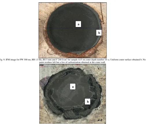
Fig. 9. IFM image for PW 300 ms, RR 1.5 Hz, BS 5 mm and F 240 J/cm2 for sample A15 on crater depth number 10: a. Uniform crater surface obtained b. No
paint residues left but a few of carbonization obtained at the crater wall.
Fig. 10. IFM image for PW 200 ms, RR 1.5 Hz, BS 5 mm and F 240 J/cm2 for sample B14 on crater depth number 10: a. Uniform surface texture of crater depth
b. Thin residues of paint flakes attached around the crater wall obtained carbonization.
a
a
b
Fig. 11. IFM image for PW 300 ms, RR 1.5 Hz, BS 5 mm and F 240 J/cm2 for sample C15 on crater depth number 10: a. Uniform surface texture at the centre of crater depth b. Thick residues of unremoved top and base surface layers and major carbonization occurred c. Effected of surface painted layer outside the
irradiated area due to non-uniform of thermalization.
3.1 Factors in increasing the substrate temperature
Average temperature changes ΔTAV (0C) was increased as laser F energy increased, but did not give any clear information effects to the small range scale of RR and PW as shown in the Tables II. From the results, the highest ΔTAV (0C) for sample A, B and C were 34.89 ° C, 32.6 ° C and 33.15 ° C, respectively. Meanwhile, the maximum temperature reach, Tmax was 40.0 ° C for sample A, 38.25 ° C for sample B and 40.3 ° C for sample C as shown in Figure 4, 6 and 8, respectively. From the results, Tmax was considered to obtain at F 240 J/cm2, RR 1.5 Hz, and BS 5 mm for all three types of substrate sample as shown in Table I. However, the substrate sample with Tmax obtained was not produced the highest ΔTAV (
0
C) for sample B and C but conversely happen to sample A as shown in Figure 6, 8 and 4, respectively. This condition might be due to the random diffusivity of temperature into the painted material of sample B and C. In addition, the density of the plumes produced during the paint stripping process was also influenced the thermal conductivity [17]. This condition was reduced the dissipation of laser beam onto the target material and directly reduced the ΔT (0C) of the metal substrates.
Furthermore, the results also show that the highest ΔTAV (0C) for all three type of substrate sample were always obtained at 5 mm beam size whereas the lowest ΔTAV (0C) measurements were obtained at 3 mm beam size as shown in Table II. Since the coating was a good insulator and has low thermal conductivity, the size of irradiated area on coating surface plays as a major role for temperature distribution. Thus, wider irradiated area was provides more space for thermocouple sensitivity probe to detect the ΔT (0C) behind the irradiated area.
3.2 Effects to the paint material
During laser paint removal process, some portion of laser beam energy was absorbed by the painted material and induced a temperature gradient that depends on its absorptivity [14]. Since diffusivity inside the painted material was very low, thermal effects was characterized by thermal diffusion length, LT as explained in the Equation 1. The LT described the distance over which ΔT (0C) propagated in some characteristics time of pulse duration [18].
Paint material was melted as the temperature increased, which leads to loosen and roughen the crater surface [14, 15, 19]. The LT gives significant effects to alter the paint material characteristics since the laser used was within long PW regime, [8, 10, 15, 20, 21]. Hence, the melting and carbonization of paint residues due to thermalization at heat affected zone (HAZ) was considered inevitable to occur during the stripping process.
By the way, metallic types of sample A and B which consisted of Al flakes which has high thermal conductivity was considered to intensify the diffusivity of painted material, hence increased the uniformity and widen the LT process to occur. Meanwhile, solid (non-metallic) acrylic paint tends to lowest diffusivity of sample C, which leads to shorter the LT. This condition leads the thermal interactions to occur only at small restricted area of painted material. Thus, the results show the paint residues and carbonization was obtained more on sample C, followed by sample B and sample A as shown in Figure 11, 10 and 9, respectively.
3.3 Effects to the metal substrate
Metal substrates of samples A, B and C for this study were considered excluded from thermal damage since the
a
b
International Journal of Engineering & Technology IJET-IJENS Vol:14 No:02 48
whole layer of painted material was not totally removed as shown in Figures 9 -11. This is because paint residue layers were still existed after laser irradiation due to the redeposition process was always occurred. It was noted that thermal damage only critical when the entire paint layer was totally removed and the metal substrate is directly irradiated [11].
For this study, all the ΔT (0C) for sample A, B and C were ranged from 24 – 40 ° C, which considered in safe thermal regime for ordinary metal substrate as shown in Figures 3 – 8 [11]. Thus, it was assumed the thermal effect mainly occurred in the paint material of samples A, B and C instead of metal substrates as shown in Figures 9 – 11.
Moreover, the Nd:YAG laser used in this study was categorized as low power laser unit which enables to produce 70.7 Watt maximum power. Hence, thermal effect to the metal substrate was considered very low and did not give any significant impacts. In addition, ability of laser penetration depth to reach the metal substrate behind the painted material was considered very weak since long PW laser parameter produced a broad energy range. These conditions reduced the risk of thermal damage on the surface and inside of the metal substrates.
4. CONCLUSION
Changing of the metal substrate temperature, ΔT (0C) is depending on thermal diffusivity of the painted material as well as the F, PW, RR and BS of laser irradiation. The maximum ΔTAV (0C) reached were 30.36 and 34.89 with BS 3 mm and 5 mm for sample A, 30.25 and 32.6 with BS 3 mm and 5 mm for sample B whereas 28.16 and 33.15 with BS 3 mm and 5 mm for sample C. All the ΔT (0C) for sample A, B and C were ranged from 24 – 40 ° C. This thermal effect was considered did not give any risk to the metal substrate for all available laser parameters applied but dominantly effected the painted material via thermalization process.
ACKNOWLEDGMENT
The authors acknowledge the support of the Research University-Postgraduate Research Grant Scheme (RU-PRGS) [Grant Number 1001/PFIZIK/845008] awarded by Universiti Sains Malaysia. Great appreciation goes to Ministry of Higher Education and Universiti Malaysia Kelantan for providing a scholarship and financial assistance for this research project. Appreciation also goes to Mr. Mohd Ashamuddin Hashim of the School of Mechanical Engineering, Universiti Sains Malaysia for his help in Alicona IFM G4 analysis.
REFERENCES
[1] Walters, C.T., B.E. Campbell, and R.J. Hull. Laser cleaning of metal surfaces. in High-Power Laser Ablation. 1998: International Society for Optics and Photonics.
[2] Razab, A.A., et al., A study of particulate matter concentration released during laser paint removal process on car coated substrate. IOSR Journal of Applied Physics (IOSR-JAP), 2014.
6(2): p. 40 - 48.
[3] Schmidt, M., L. Li, and J. Spencer, An investigation into the feasibility and characteristics of using a 2.5 kW high power diode laser for paint stripping. Journal of Materials Processing Technology, 2003. 138(1): p. 109-115.
[4] Shu-Dong, S., et al., Removing paint from a metal substrate using a flattened top laser. Chinese Physics B, 2012. 21(10): p. 104209. [5] Lu, Y.-F., et al., Laser surface cleaning in air: mechanisms and
applications. Japanese journal of applied physics, 1994. 33(part 1): p. 7138-7143.
[6] Bäuerle, D., Laser processing and chemistry. 2011: Springer. [7] Poprawe, R., Tailored Light 2: Laser Application Technology. Vol.
2. 2011: Springerverlag Berlin Heidelberg.
[8] Targowski, P., et al. Picosecond laser ablation system with process control by Optical Coherence Tomography. in SPIE Europe Optical Metrology. 2009: International Society for Optics and Photonics.
[9] Vorobyev, A.Y. and C. Guo. Residual thermal effects in laser ablation of metals. in Journal of Physics: Conference Series. 2007: IOP Publishing.
[10] Brygo, F., et al., Laser fluence, repetition rate and pulse duration effects on paint ablation. Applied surface science, 2006. 252(6): p. 2131-2138.
[11] Coutouly, J.-F., et al., Optimisation of a paint coating ablation process by CO2 TEA laser: Thermal field modelling and real-time
monitoring of the process. Journal of Materials Processing Technology, 2009. 209(17): p. 5730-5735.
[12] Rode, A., et al., Scanning the laser beam for ultrafast pulse laser cleaning of paint. Applied Physics A, 2008. 93(1): p. 135-139. [13] Liu, K. and E. Garmire, Paint removal using lasers. Applied
optics, 1995. 34(21): p. 4409-4415.
[14] Labuschagne, K. and S. Pityana, Laser induced damage threshold on metallic surfaces during laser cleaning. 2005.
[15] Razab, M.K.A.A., et al., Identification of optimum operatives parameters for Pulse Nd: YAG laser in paint removal on different types of car coated substrate. International Journal of Education and Research, 2014. 2(2).
[16] Alicona, I.G., IFM G4 3.5.1.5 EN 27.04. 2011. Alicona GmbH, 2011.
[17] Mościcki, T., J. Hoffman, and Z. Szymański, Modelling of plasma formation during nanosecond laser ablation. Archives of Mechanics, 2011. 63(2): p. 99–116.
[18] Brown, M.S. and C.B. Arnold, Fundamentals of Laser-Material Interaction and Application to Multiscale Surface Modification, in
Laser Precision Microfabrication. 2010, Springer. p. 91-120. [19] Chen, G., et al., Laser cleaning of steel for paint removal. Applied
Physics A, 2010. 101(2): p. 249-253.
[20] Malavallon, O., Paint Removal Principles. AGARD, 1995. [21] Razab, A.A., et al., Determination of Average Coating Removal