ISSN (Online): 2320-9364, ISSN (Print): 2320-9356
www.ijres.org Volume 5 Issue 3 ǁ Mar. 2017 ǁ PP.08-12
Finite Element Analysis of Roll Cage
Malatesh Godi
1, Md.Manazir
1, Bhuvan Harlapur
1, N.Chitresh
1.
1Ug Scholar, Mechanical Engineering, B.V.B. College Of Engineering And Technology, HubliABSTRACT:
The roll cage is used as a structural base for all terrain vehicles and it also protects the occupant in case of impact and roll-over accidents so determining the strength and impact withstanding capacity of the roll Cage plays important role for the design and it is also a supporting structure for the engine. Most of the forces are taken up by the roll cage.This paper aims at Finite Element analysis of roll cage. Stress analysis carried out using Ansys workbench and it includes torsional analysis .modal analysis for the maximum operating speed of the vehicle.Key words: Roll cage, Modal analysis, Static analysis, Fatigue life.
I.
INTRODUCTION
A Roll Cage is protective outer frame of an automobile, sometimes referred as skeleton of an automobile. The main function is to provide safety to the driver and passengers in case of an accident or a roll over.
II.
DESIGN OF ROLL CAGE
As the roll cage is used for the protection of the driver and passenger, it has to have high strength. This might lead to heavy weight of the vehicle. For this reason the roll cage is made of hollow tubes of material C45. The model of the roll cage was generated in Solid works modelling software and later analyzed through Ansys software. Dimensions were referred from the Baja rulebook.
Figure 1 Dimensions of the roll cage
III. Material
To make a high strength and low weight roll cage the material selection is a critical parameter. The properties of the material is following.
Subject Property
Material Name C 45 Poisson’s Ratio 0 .290
Density 7850kg/m^3
yield strength(tensile) 515MPa
Ultimate strength (tensile) 655MPa
Bulk modulus 1.627*10^2GPa
Shear modulus 79.457GPa
Table: 2 Material of roll cage
The materialcomposition isshown in below table.
Material Name Composition
Carbon, C 0.42 - 0.50 % Iron, Fe 98.51 - 98.98 % Manganese, Mn 0.60 - 0.90 % Phosphorous, P <= 0.040 % Sulfur, S <= 0.050 %
Table: 3 Material composition
Later the total weight of roll cage is calculated. Total Volume of the model: 4.872e+006 mm³ Total Mass of the model: 38.245 kg
Max. Mass of person (assumed): 100 kg
Mass of additional parts attached to the roll cage (assumed): 60kg Total Mass = 200 kg.
[Ref 1, 2, 3, 4, 5, 6, 7].
IV. FINITE ELEMENT ANALYSIS
After finalizing the material type and total weight of roll cage, we further analyze the model in Ansys software for different type of loadings.As the total weight carried by roll cage is around 200kg, the force due to acceleration is three times that of the total weight i.e. 200 X 3 =600 Kg=6000N.
By the following equation we found the velocity of the vehicle. Kinetic energy of vehicle = kinetic energy of the roll cage. Therefore the velocity of the vehicle is 40.8m/s.
4.1 Meshing the model
The meshing is done by Ansys pre-processor. Default mesh control with 18318 elements and 39412 nodes are generated.
4.2 Static structural analysis 4.2.1 Boundary Conditions
Initially the base is fixed assuming that the loading takes place on the upper plane of the base due to these: i. Weight of the roll cage and vehicle parts.
ii. Weight of person.
iii. Acceleration of the vehicle.
Figure
3 Fixed Support
This type of the analysis is carried out because of the load of the vehicle acts on the roll cage. The load acts on the four parts where the wheels are fixed.
Figure 3 Method 1
4.2.2 Results of static analysis
Figure 6 Stress for Method 2
Figure 7 Deformation for Method 1
Figure 8 Deformation for Method
Loading Type1 Loading Type 2 Equivalent stress 307.59Mpa 277.83Mpa Total
deformation
20.854 mm 19.364 mm
Table: 4 Static analysis results
As the maximum deflection of the model is 20.854mm which is less than 76.2(3 inches) hence the design is safe. The deflection is considered because it is the clearance between the rider and the roll cage. [Ref 8]
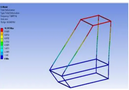
4.3 Modal Analysis:
The modal analysis is done to know the different natural frequency of the roll cage, because the resonance occur when the external frequency matches the natural frequency of the vehicle. So the vehicle is not run at these speeds or these speeds are past by very quickly.
Figure 9 Modal analysis: Mode1
Figure 11 Modal analysis: Mode3 Mode 1 Mode2 Mode3 Frequency
(Hz)
7.6497 10.422 16.498
Total deformation
10.305 mm 9.7753 mm 10.624 mm
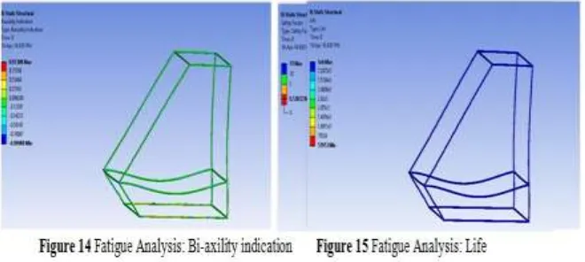
4.4Fatigue Analysis:
As it is the all-terrain-vehicle cyclic load acts on it, hence the fatigue analysis has to be done on the vehicle. Figure 12 Fatigue Analysis: Safety Factor
Figure 13 Fatigue Analysis: Safety Factor critical section
Results of fatigue analysis:
i. The equivalent alternating stress obtained is 160.13Mpa and it is less than the 327.5Mpa.i.e. it is less than the endurance limit of the material.[ref 1-7]
ii. According to the above analysis maximum fatigue life for the roll cage is 10^6.
iii. Factor of safety for the design varies from 0-15 and we obtained the factor of safety as 0.538.
Name Figure Design life Minimum maximum
Life Fig 15 52953 1.0X10⁶
Damage None 1.0X10⁶ 1000 1000
Safety factor Fig 12&13 1.0X10⁶ 0.538 15 Bi-axiality indication Fig 14 - - -0.9999 0.9998 Equivalent alternating stress None - - 0.01Mpa 160.13Mpa
Table:6 Fatigue results
III.
CONCLUSION
Roll cage used for the all-terrain vehicles is necessary to be analyzed in the context of maximum safe load that the design can withstand and hence from the static structural analysis of the roll cage it is clear that for the overall load of 6000N which is acting on the roll cage generates a stress of 307.59 MPa and it is within the yield stress which is 515Mpa hence the design is safe. From the modal analysis of roll cage 3 modes of vibrations are obtained (table 4) and from the fundamentals of vibrations it is clear that any force corresponding to those natural frequencies should not act on the roll cage and the roll cage should not be subjected any load corresponding to those frequencies .From the fatigue analysis of the roll cage maximum alternating stress developed was 160.13Mpa which is less than the endurance limit of 327.5 Mpa and the design is safe for the fatigue load also and it has a design life of 10^6 cycles.
REFERENCES
[1]. ASM Metals Reference Book, Third edition, Michael Bauccio, Ed. ASM International, Materials Park, OH, 1993.
[2]. ASM Specialty Handbook - Carbon and Alloy Steels, edited by J.R. Davis, Davis & Associates, ASM International, Metals Park, OH, (1996).
[3]. Engineering Properties of Steels, Philip D. Harvey, editor, American Society for Metals, Metals Park, OH, (1982).
[4]. Metals Handbook, Vol.1 - Properties and Selection: Irons, Steels, and High-Performance Alloys, ASM International 10th Ed. 1990.
[5]. Metals Handbook, Howard E. Boyer and Timothy L. Gall, Eds., American Society for Metals, Materials Park, OH, 1985.
[6]. Physics for Scientists and Engineers with Modern Physics, 2nd ed., Douglas C. Giancoli, Prentice Hall Publishers, Englewood Cliffs, NJ (1989).
[7]. SAE Ferrous Materials Standards Manual, 1999 ed., HS-30, Society of Automotive Engineers, Inc., Warrendale, PA, (1999).