Capacity and Performance Analysis of STC MBOFDM UWB
Systems
Ines Ben Hassine*, Ridha Bouallegue
Innov'Com Laboratory, Higher School of communications Of Tunis, Sup’COM, Carthage University, Tunis, Tunisia.
* Corresponding author. Email: [email protected] Manuscript submitted January 10, 2015; accepted May 5, 2015. doi: 10.17706/jcp.10.3.203‐212
Abstract: Next generation communication systems aim mainly to data throughput improvement for any wireless channel conditions. According to Shannon formula, UWB system with gigahertz band can reach ultra‐high data transmission rate. Multiband orthogonal frequency division multiplexing (MB‐OFDM) for ultra wideband (UWB) technology presents a potential candidate for the diverse set of high‐rate performance short‐range applications. When combined with a multiple‐input multiple‐output (MIMO) and a space time code (STC) transmission scheme, MB‐OFDM UWB presents a viable way to improve channel capacity and expand coverage area. This paper presents an analysis on the capacity and performance of MIMO STC‐MB‐OFDM systems over UWB channels. Also, this work will compare the Alamouti code and the algebraic space–time–code (ASTC) capacity when used in MIMO MB‐OFDM system. It will be shown that ASTC code can provide significantly higher channel capacity and better BER performance when used in a MIMO MB‐OFDM system.
Key words: BER, channel capacity, MB‐OFDM UWB, MIMO, STC.
1.
Introduction
Recently the heavier use of digital imaging and multimedia applications introduce huge demands for high data rate wireless links. Due to its use of a high‐frequency bandwidth, UWB system is a good candidate to meet such requirement by offering high data rates for a low cost and at a low transmission power level [1]. Federal communications commission (FCC) has already assigned the spectrum from 3.1 GHz to 10.6 GHz for unlicensed use by UWB applications [2].
Information theory indicates that by exploiting appropriate space–time signal‐processing techniques in a multipath wireless channel scattering, a multi‐input–multi‐output (MIMO) system is able to support enormous capacities [3]. By using a temporal and a spatial multiplexing modulation, the space‐time codes (STC) are used to improve MIMO performances. Among various STCs, of particular interest are the Alamouti codes [4] and the Algebraic Space‐Time Codes (ASTCs), which have many advantages than other STCs [5].
Indeed, the association of UWB MB‐OFDM, MIMO, and STCs technologies will provide a significant improvement in the maximum achievable communications range, bit error performance, data rate and also system capacity.
specifications. In Section 3, we analyze the mathematical model of STC MIMO MB‐OFDM system. In Section 4, we present the channel capacity expression. Simulation results are mentioned in Section 5 and conclusions are drawn in Section 6.
2.
MB
OFDM
UWB
Overview
The technique for designing an MB‐OFDM UWB system is to combine OFDM modulation technique with a multi‐banding. The spectrum is divided into several sub‐bands, whose bandwidth is approximately 500 MHz [6], [7]. The system operates in one sub‐band and then switches to another sub‐band after a short time. In each sub‐band, OFDM modulation is used to transmit data symbols. In order to exploit the spectral diversity, the transmitted symbols are time interleaved across the sub‐bands. This approach possess many advantages such as: having the same average transmitted power as a system operating over the entire bandwidth, processing the information over much smaller bandwidth, which reduces power consumption and lowers cost, improving spectral flexibility and worldwide compliance.
For MB‐OFDM transmission, the bandwidth is subdivided into five frequency parts [8]. Each part is divided into sub‐bands, each having a bandwidth of 528 MHz. In each sub‐band, orthogonal frequency division multiplexing (OFDM) is applied. Frequency Hoping (FH) between different bands is supported so that the transmitted signal hops between sub‐bands in every OFDM symbol duration that is 312.5 ns [7]. Fig. 1 presents the MB‐OFDM spectrum allocation. Each sub‐band contains 128 subcarriers. Ten of these are used as guard tones, twelve of the subcarriers are devoted to the pilot signals, and 100 are for information. The remaining six tones are set to zero, according to [7]. Different information data rates of 55, 80, 110, 160, 200, 320, and 480 Mb/s can be achieved. The system parameters for the MB‐OFDM solution are given in Table 1.
MB‐OFDM system utilizes time‐frequency coding (TFC) to interleave data over sub‐bands. As an example in Fig. 2, TFC is performed over three OFDM symbols and sub‐bands and using a TFC of length 3. The TFCs are used not only to supply frequency diversity in the system, but also to supply multiple accesses. Guard intervals of 9.47 ns are providing sufficient time for transmitter and receiver to switch to the next carrier frequency.
Fig. 1. Band allocation for MB‐OFDM system. Fig. 2. TFC over three OFDM symbols.
3.
STC
MB
OFDM
MIMO
System
frequency division multiplexing (OFDM) modulation. ASTC codes combined with OFDM modulation maintain their properties and outperform the classical Alamouti MIMO‐OFDM systems [5]. In this sub‐section, we propose to study the ASTC codes under UWB channel and for a MB‐OFDM system design compared to Alamouti‐MB‐OFDM one.
Table 1. System Parameters for the MB‐OFDM System
3.1.
System
Model
The fundamental transmitter and receiver structure of an STC MB‐OFDM system is illustrated in Fig. 3. At the transmitter, binary information sources are first whitened by the scrambler, then encoded by the convolutional encoder and afterwards interleaved in order to exploit time–frequency diversity and combat multipath fading. The resulting bit sequence is mapped into constellation symbols. Let’s denote S=[S1, S2,
..., Sn] of size N= n*Nfft, where Nfft is the number of subcarriers of the OFDM modulator, defined as an OFDM
packet. Structures of S are the same as the structure of OFDM system, except that every element Si is a
column vector and not a number, Si=[Si,1, Si,2, ..., Si,Nfft]T. The vectors Si are the original transmitted data
before IFFT. The vectors Si,j are drown from a QPSK constellation.
The traditional single antenna MB‐OFDM system can be improved by exploiting the space‐time code (STC), with Nt transmit antenna and Nr receive antenna. In this section, we consider the Alamouti code and
the proposed ASTC code in MB‐OFDM system using Nt=2 transmit antennas and any number of receive
antennas. The STC transmission matrix XSTC corresponding to Alamouti code is:
⎥
⎦
⎤
⎢
⎣
⎡
−
=
+ +
* *
1 1
i i
i i Alamouti
S
S
S
S
X
(1)For the ASTC code, let’s denote vk=[S4k−3, S4k−2, S4k−1, S4k]T the mapped symbols (k=1…n/4). The STC
transmission matrix XSTC corresponding to ASTC code is given by:
⎟⎟
⎠ ⎞ ⎜⎜
⎝ ⎛
+ +
+ +
=
)) 2 ( ) 1 ( ( )) 4 ( ) 3 ( (
)) 4 ( ) 3 ( ( )) 2 ( ) 1 ( ( . 5 1
k k k
k
k k k
k ASTC
v v v
v
v v v
v X
θ
α
θ
α
θ
α
θ
α
(2)
where
2 5
1+
=
θ ,
2 5 1− =
θ , α =1+i−iθ ,
α
=
1
+
i
−
i
θ
.We are coding L=4*Nfft symbols at the same time with ASTC code; however we code only 2*Nfft symbols
T n i n i n i n i Alamouti i i i i
S
S
S
S
X
⎟
⎟
⎟
⎟
⎟
⎠
⎞
⎜
⎜
⎜
⎜
⎜
⎝
⎛
−
=
+ + + + ) 2 , ( * ) 2 , ( 1 ) 1 , ( * 1 ) 1 , ( 1 1)
(
)
(
)
(
)
(
(3) T n k k n k k n k k n k k k ASTC i i i i v v v v v v v v v X ⎟ ⎟ ⎟ ⎟ ⎟ ⎠ ⎞ ⎜ ⎜ ⎜ ⎜ ⎜ ⎝ ⎛ + + + + = Φ = + + ) 2 , ( ) 2 , ( ) 1 , ( ) 1 , ( 1 1 ))] 2 ( ) 1 ( ( [ ))] 4 ( ) 3 ( ( [ ))] 4 ( ) 3 ( ( [ ))] 2 ( ) 1 ( ( [ . 5 1 . θ α θ α θ α θ α (4) where ⎟⎟ ⎟ ⎟ ⎟ ⎠ ⎞ ⎜⎜ ⎜ ⎜ ⎜ ⎝ ⎛ = Φ 0 0 0 0 0 0 0 0 αθ α αθ α αθ α αθ α ii (5)
After applying the Nfft‐point IFFTs of STC transmission matrix elements, we have
X
OFDM=
{
IFFT
{
X
STC,i}
} {
=
x
OFDM,i}
(6)where fft fft N k j N k i STC fft i
OFDM
X
k
e
N
x
π 2 1 0 , ,(
)
1
∑
−=
=
(7)A cyclic prefix of length NCP (NCP ≤ Nfft) is added to the IFFT rows outputs to eliminate ISI. Let’s denote XCP= {
x
CP,i} where CPi[
CPi CPi CPiN N]
TCP fft
x
x
x
x
;=
,,1,
,,2,....,
,, +i CP
x
, are converted into a continuous‐time baseband signalx
i,n(
t
)
(n=1...Nt) for transmission: elementsk i CP
x
,, in each row of XCP are transmitted in the same frequency band, whereas different rows of XCP mightdevolve in different frequency bands, by applying a certain TFC. As shown in Fig. 2, the first row of XCP is
transmitted on sub‐band 1, the second row is transmitted on sub‐band 3, the third row is transmitted on sub‐band 2, the fourth row is transmitted on sub‐band 1, and so on.
(a) (b)
Fig. 3. Block diagrams of the transmitter (a) and the receiver (b) of an STC‐MB‐OFDM system.
The statistical description of the IEEE 802.15.3a UWB channel employs a Saleh–Valenzuela model [10]. This model describes the time of arrival of the scattered rays at the receiver after multipath propagation where multipath components arrive in clusters. Independent fading is assumed for each cluster as well as each ray within the cluster. In MIMO systems we deal with the space diversity of the multi‐antenna. In order to reflect this effect, the antenna relativity is neglected; therefore we may rewrite the channel model expression as:
∑∑
= =−
−
=
L l K k l k j i l j i l k j i ji
t
X
t
T
h
0 0 , , , , ,,
(
)
α
δ
(
τ
)
(8)where
α
k,l are the multipath gain coefficients, l refers to the cluster, and k refers to the arrival within the cluster; Tl is the delay of the l‐th cluster;τ
k,l is the delay of the k‐th multipath component relative to thel‐th cluster arrival time Tl ; X is the log‐normal shadowing. i and j represent the i‐th transmit and the j‐th
receive antenna. We define a Nr× Nt step matrix Hk,t , as follows:
⎥
⎥
⎥
⎥
⎦
⎤
⎢
⎢
⎢
⎢
⎣
⎡
=
t k NrNt t k Nr t k Nr t k Nt t k t k t k Nt t k t k t kh
h
h
h
h
h
h
h
h
H
, , 2 , 1 , 2 , 22 , 21 , 1 , 12 , 11 ,…
…
…
(9)
where kt m n
h
,, expressed channel frequency response from the n‐th transmission antenna to the m‐th receiveantenna in the k‐th subcarrier at the t time.
3.3.
Receiver
Structure
The signal received at each receive antenna is a superposition of the Nt transmitted signals corrupted by
additive white Gaussian noise t m
w
:t
m t m n Nr n n i m
i
t
x
t
h
w
r
=
∑
⊗
+
=1 ,
,
,
(
)
(
)
n=1…Nt, m=1..Nr (10)where
⊗
defines linear convolution and[
N t]
m n t m n t m n t m n fft
h
h
h
h
,=
1,,,
2,,,....,
, , .The received RF signal at each receive antenna is down‐converted to a complex baseband signal, and then sampled before passing through an OFDM demodulator to have
X
ˆ
CP=
{
x
ˆ
CP,i,n}
, n=1..Nt. After carrierdemodulation and CP elimination, we can apply this linear convolution property: ,, ,
(
(
,,)
(
,))
t m n n i OFDM t m n n iOFDM
h
IFFT
FFT
x
FFT
h
x
⊗
=
•
=
IFFT
(
X
STC,i,n•
n,m)
(11)where
•
defines element‐wise (or Hadamard) product andT Nfft m n m n m n t m n m
n,
=
FFT
(
h
,)
=
[
, ,1,
, ,2,...,
, ,]
.Then we perform the unitary fast Fourier transform on the remaining streams
∑
=+
•
=
Nt n m m n n STCm
X
w
r
1
,
, n=1…Nt, m=1..Nr (12)
where
[
]
fft N m m m t m
m
FFT
w
w
w
w
w
ˆ
=
(
ˆ
)
=
ˆ
,1,
ˆ
,2,...,
ˆ
,We can rewrite the last equation in matrix form as follows
In fact mathematical model of wireless STC MIMO system and the STC MB‐OFDM UWB system are similar except that the matrix elements are scalar numbers in the conventional STC MIMO system, while they are Nfft‐length vectors in the STC MB‐OFDM UWB system. The ML decoding algorithm is then applied
{ }
{ } 2min
arg
ˆ F s H S RS = − • (14)
S has the similar structures as the conventional STCs, so the MB‐OFDM symbols Si preserve their
orthogonality, and the ML decoding metric isn’t too complicated to be performed. Therefore, the STC MB‐OFDM UWB decoding preserve decoding simplicity, i.e., each MB‐OFDM symbol Si can be decoded
separately, rather than jointly. Thus, based on decoding metrics for the respective STC of S, decoding metrics for the MB‐OFDM symbols Si will be readily to find. Thus the decoding process is completely linear,
and relatively simple.
3.3.1.
Alamouti
MB
OFDM
decoding
process
At the receiver side, we can re‐express the received signal by antenna m during two time slots as
⎥ ⎦ ⎤ ⎢ ⎣ ⎡ + ⎥ ⎦ ⎤ ⎢ ⎣ ⎡ ⎥ ⎦ ⎤ ⎢ ⎣ ⎡ − = ⎥ ⎦ ⎤ ⎢ ⎣ ⎡ ∗ ∗ m m m m m m w w S S S S r r , 2 , 1 , 2 , 1 1 2 2 1 , 2 ,
1 (15)
Which can be written as
⎥
⎦
⎤
⎢
⎣
⎡
+
⎥
⎦
⎤
⎢
⎣
⎡
⎥
⎦
⎤
⎢
⎣
⎡
−
=
⎥
⎦
⎤
⎢
⎣
⎡
∗ ∗ ∗ ∗ m m m m m m m mw
w
S
S
r
r
, 2 , 1 2 1 , 1 , 2 , 2 , 1 , 2 ,1 (16)
This is equivalent to *
ˆ
ˆ
mw
S
H
r
m=
m+
, m=1,2,…Nr, whereH
H
m mI
H m
m
(
)
2 2 , 2 1 ,
+
=
. We assume that the receiver has full channel knowledge, a decision statistics can be obtained as⎥
=
=
+
∗⎦
⎤
⎢
⎣
⎡
=
m H m m H m m H m m mm
H
r
H
H
S
H
w
z
z
z
, 2 , 1(17)
Adding all statistics from all Nr receive antennas yields
∑
∑
∑
= = =⎥
⎦
⎤
⎢
⎣
⎡
+
⎥
⎦
⎤
⎢
⎣
⎡
+
=
⎥
⎦
⎤
⎢
⎣
⎡
=
⎥
⎦
⎤
⎢
⎣
⎡
=
r r Nrm m m N m m m N m m m
w
w
S
S
z
z
z
z
z
1 2, , 1 1 2 1 2 2 , 2 1 , 1 2,
, 1 2
1
)
(
(18)where
w
1,m andw
2,m are the noise terms. Thus, due to the space‐time code design and the receive side treatment, the decoding processing is simplified: data symbols S1 and S2 are decoupled and can be decodedindependently.
In the case of Nt=2 and Nr=1, we use Alamouti property to restitute original symbols, thus the ML
decision rule can be stated as: 2 1 * 2 1 , 2 1 * 1 , 1
1 argmin( )
ˆ
F
r S S
S = • + • −
(19)
2 1 * 2 1 , 1 1 * 1 , 2
2 argmin( )
ˆ
F
r S S
S = • − • −
3.3.2.
ASTC
MB
OFDM
decoding
process
At time (ni, ni+1), equation (14) can be re‐written as
i i
i n ASTC n
n
H
X
w
where
⎥ ⎥ ⎥ ⎥ ⎥
⎦ ⎤
⎢ ⎢ ⎢ ⎢ ⎢
⎣ ⎡
=
+ + +
+
1 2 , 2 2 , 1
1 1 , 2 1 , 1 1 2 , 2 2 , 1
1 1 , 2 1 , 1
0 0
0 0
0 0
0 0
i i
i i i i
i i
i
n n
n n n n
n n
n
H (21)
where ni are the N
fft channel coefficients at time ni. To decode the received signal we use the MMSE
decoder. The solution of the linear MMSE is given by [11]:
H m
m m H m
MMSE
I
H
H
H
R
SNR
X
ˆ
=
(
1
+
)
−1.
(22)where
H
m is a N*4 matrix,R
m is a N*1 vector and I is the identity N*N matrix. After channel compensation, we decode the decision variableX
ˆ
MMSE by using zero forcing sub‐optimum decoder whichreduces the numerical complexity without significant performance loss. The decision vector for each L transmitted symbol is then
v
MMSE=
Φ
−1X
ˆ
MMSE (23)4.
Channel
Capacity
In this part we determine the analytic capacity expression of MIMO STC‐MB‐OFDM system. First of all we should determine the mutual information between transmitted information S and received information R. Then we can deduce the analytic expression of the information capacity of an STC‐MB‐OFDM system for a given channel matrix H. The mutual information is given by
I
(
S
,
R
)
=
Η
(
R
)
−
Η
(
R
S
)
=
Η
(
R
)
−
Η
(
W
)
(24)where Η( )R denotes the entropies of multivariate distribution R. The capacity is obtained by maximizing
the mutual information
C=max(I(S,R))=max(Η(R))−Η(W) (25)
So we have to determine the exact expression of Η( )R to obtain the capacity expression. For a MIMO
Alamouti system, the capacity expression is given by [12]:
⎥
⎦
⎤
⎢
⎣
⎡
+
=
log
2det(
H
H
)
N
I
C
Ht Nr
ρ
bits
/
s
/
Hz
(26)where
ρ
presents mean signal to noise ratio.It has been shown in [13] that the expression of the capacity of a MIMO ASTC system can be expressed as
⎥
⎦ ⎤ ⎢
⎣ ⎡
+
=log2 det(I * 12 Q H H )
C X H
W Nt
Nfft
σ
bits
/
s
/
Hz
(27)where
Q
Xis the covariance matrix and can be expressed as
{
H}
Nfft NtX
I
Q
=
Φ
Φ
* (28)and
Φ
is a copy ofΦ
(Nfft*Nt/4) times.log ( 1 1 . . . 2 ) 2
2 ⎥
⎦ ⎤ ⎢
⎣ ⎡
+
≤ h
w
P L Nt Nfft C
σ
(29)where Ph denotes the power to each channel coefficient in time domain.
5.
Simulation
Results
In this part, we first begin by analyzing the BER performance and then the capacity of MIMO MB‐OFDM system under UWB channels, and using two STC coding schemes: the Alamouti code and the ASTC code.
5.1.
ASTC
MB
OFDM
UWB
vs.
Alamouti
MB
OFDM
UWB
Performances
Compared to the conventional MB‐OFDM system, simulation results in Fig. 4 show that the Alamouti MB‐OFDM system achieves a significant improvement in bit error ratios (BER). The use of tow Rx and Tx antennas evolves the BER of Alamouti MB‐OFDM systems by approximately 5 dB at BER = 10−3 for CM1
channel.
By comparing the BER performances of the ASTC code and the classical Alamouti code in UWB MB‐OFDM environment for two Rx antennas, we can see that for a high SNR, the ASTC code have a good performance in terms of BER. It provides a gain of about 4 dB for a BER equal to 10‐4 and for CM1 channel, compared to
Alamouti code. This gain comes from the fact that we are coding 4*Nfft symbols at the same time with
Golden code, however we code only 2*Nfft symbols with Alamouti code, then the gain still significant in
terms of rate.
0 5 10 15
10-7 10-6 10-5 10-4 10-3 10-2 10-1 100
SNR(dB)
B
it
E
rro
r
ra
te
MB-OFDM,SISO,CM1 Alamouti MB-OFDM,CM1 Alamouti MB-OFDM,CM2 Alamouti MB-OFDM,CM3 Alamouti MB-OFDM,CM4 ASTC MB-OFDM,CM1 ASTC MB-OFDM,CM2 ASTC MB-OFDM,CM3 ASTC MB-OFDM,CM4
Fig. 4. Performance of SISO MB‐OFDM UWB system, Almouti MB‐OFDM UWB system and ASTC MB‐OFDM UWB system.
5.2.
Capacity
Analysis
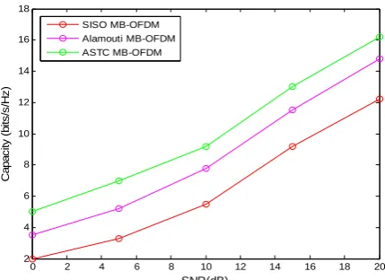
In this section we present a comparison between the capacity of a SISO MB‐OFDM system (using one Tx antenna and one Rx antenna), the capacity of a MIMO Alamouti MB‐OFDM system and the capacity of a MIMO ASTC MB‐OFDM.
0 2 4 6 8 10 12 14 16 18 20 2
4 6 8 10 12 14 16 18
SNR(dB)
C
a
p
a
ci
ty (
b
it
s/
s
/H
z
)
SISO MB-OFDM Alamouti MB-OFDM ASTC MB-OFDM
Fig. 5. Capacity of SISO MB‐OFDM UWB system, Almouti MB‐OFDM UWB system and ASTC MB‐OFDM UWB system.
6.
Conclusions
MB‐OFDM UWB technology presents a potential candidate for the diverse set of high‐performance short‐range applications. In this paper, we have studied a MIMO MB‐OFDM UWB system performance using two schemes of space‐time‐coding, in terms of BER and capacity. Numerical results show that ASTC code has a reasonable BER performance and capacity that outperform the classical Alamouti code when implemented in an UWB MB‐OFDM system over various realistic UWB channels.
References
[1] Roy, S., Foerster, J. R., Somayazulu, V. S., & Leeper, D. G. (2004). Ultrawideband radio design: the promise of high‐speed, shortrange wireless connectivity. Proceedings of the IEEE: Vol. 92 (pp. 295‐311).
[2] Federal Communications Commission (FCC). (2002). New Public Safety Applications and Broadband
Internet Access among Uses Envisioned by FCC Authorization of UltraWideband Technology.
Washington, DC.
[3] Foschini, G. J., & Gans, M. J. (1998). On limits of wireless communications in a fading environment when using multiple antennas”. Proceedings of the Wireless Personel Communications: Vol. 6 (pp. 311–335). [4] Alamouti, S. M. (1998). A simple transmit diversity technique for wireless communications. IEEE J.
Select. Areas Commun., 16(8), 1451‐1458.
[5] Ben, H. I. & Bouallegue, R. (2013). Algebraic space time code implementation in MIMO environment: Design criteria and performance. Proceedings of International Conference on Advanced Communication
Technology (pp. 291‐294).
[6] Somayazulu, S., Foerster, J. R., & Roy, S. (2002). Design challenges for very high data rate UWB systems.
Proceedings of Asilomar on Systems, Signals, and Computation Conference (pp. 717–721).
[7] Batra, A., et al. (2003). TI physical layer proposal for IEEE 802.15 task group 3a. IEEE
P802.1503/142r2TG3a.
[8] Batra, A., et al. (2004). Multi‐band OFDM physical layer proposal for IEEE 802.15 task group 3a. Proceedings of IEEE P802.15 Working Group for Wireless Personal Area Networks (WPANs).
[9] Belfiore, J. C., Rekaya, G., & Viterbo, E. (2004). The golden code: A 2×2 full‐rate space‐time code with non‐vanishing determinants. Proceedings of International Symposium on Information Theory (pp. 310–310).
Selected Areas in Communications, 5(2), 128‐137.
[11]Mody, A. N., & Stuber, G. L. (2001). Parameter estimation for OFDM with transmit receive diversity. Proceedings of 53rd Spring IEEE Vehicular Technology Conference VTC (pp. 820–824).
[12]Sergey, L. L. (2001). Channel capacity of MIMO architecture using the exponential correlation matrix. IEEE Communications Letters, 5(9), 369‐371.
[13]Ben, H. I., & Bouallegue., R. (2013). Performances analysis of algebraic space time code under correlated and uncorrelated channels. ICACTTACT Journal, 2(4), 262‐268.
Ines Ben Hassine was born in Mahdia, Tunisia, in 1984. She received the engineering degree in telecommunications in 2008 and the M.Sc. degree in communications system in 2009 from the National Engineering School of Tunis (ENIT), Tunisia. From 2010 to 2015, she was a research associate with the Laboratory of InnovCOM (Innovation of COMunicant and COperative Mobiles), High School of Communication of Tunis, Tunisia. She is currently an assistant at the Faculty of Science of Gabès. Her research interests include MIMO, OFDM systems, space time code, UWB.