ISSN (Online): 2320-9364, ISSN (Print): 2320-9356
www.ijres.org Volume 4 Issue 3 ǁ March. 2016 ǁ PP.60-67
Simple Applications of Solidworksin Design of Products
GAO Yunlu, Zhang Chunyan
*, HE Junhui, ZHAO Junhao, ZHANG Hongliang
School of Mechanical Engineering,Shanghai University Of Engineering Science,Shanghai,China 201620
Abstract:- Based on Solidworks, explain some simple applications of software Solidworks in design of a new
kind of umbrella though an example. Modeling with Top-down method and assembling them into virtualmachine, then, using the motion simulation to check motion interference can reduce the design errors. Use the
software of Photoview 360 and Solidworks to complete the industrial design. In the end, completing the entire
toy product design process by Solidworks 2D engineering drawing module processing drawings
Keywords:- Solidworks;Top-down,Product Design;Simulation;Photoview 360
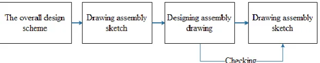
I.
INTRODUCTIONS
Solidworks, a computer-graphics aided three-dimensional interactiveapplication which is developed
completely based on Windows, is currently one of the mainstream computer-graphics aided softwares【1】 and it
includes a variety of modules, such as CAD, CAM, CAE, etc. Conforming to graphical interfaces and shortcut
operation of windows, it not only provides conveniences for many engineers and technicians to master and use
in the aspect of 3D modeling, but also greatly helps to shorten the learning cycle so as to reduce the costs of
human resources. With multinational standard parts and open secondary development environment, Solidworks
can actualize multiplayer design by using PDM and provide the function of advanced parametric modeling. The
features of relational designs can lead to the changes of manufacturing drawings according to the diversification
of the models so that it can greatly improves the drawing speed of 2D drawings, reduce errors, shorten the
development cycles and lower the development costs. All the things that mentioned above make sure that the
new products can be put on the market as soon as possible to improve the competitiveness of the company. This
thesis takes the umbrella as an example to introduce the application of Solidworks in the product design,
especially the top-down design method.
II.
UMBRELLA DESIGN
The traditional umbrella design is still adopted the method that combines the two-dimensional drawing
and manual model. Figure 1 is the umbrella model made by the traditional method, the design of which always
cannot accurately express the conception (idea) of innovation. With the development of technology, the
umbrella is developing from the one with traditional appearance and pure mechanical status to the new
interactive umbrella integrated with optical, mechanical and electronic functions. For example, Figure 2 is a
remote-controlled aircraft umbrella. To complete the design of this complex umbrella, it is required for new
design methods and new design tools. Adopting 3D software to design the umbrella has become an important
trend of modern umbrella design. It can use the entity, the surface and other parametric tools of Solidworks
Source of project:Innovation project of Shanghai College Student(cs1401002)
Top-down method to speed up the design. And then, use the built-in simulation plug-in Solidworks
Motion to finish the movement imitation and design optimization. Meanwhile, the powerful plug-in support
functions of Solidworks can help complete the industrial design of the umbrella with Keyshot rendering
software. At last, draw up the drawing according to the short-cut engineering drawing module standard in
Solidworks. The whole process is interrelated without interruption. During the design of the umbrella, these
simple applications of Solidworks can be completely qualified for the study on the new and complex umbrella
design.
Figure 1 the 3D model of the traditional umbrella Figure 2 The modern new interactive umbrella
2 The top-down design method of the umbrella
Currently, the common mechanical design methods are the traditional 2D and modern 3D. The modern
3D includes two kinds of design methods: bottom-up and top-down. The above design methods all have its
advantages and disadvantages and in different periods each plays a different role.
Figure 3 the flow Figure of traditional 2D design method
2.1 The comparison of the three design methods
With the popularity of the 3D design method, the traditional 2D has gradually been eliminated. Table 3
shows the flow Figure of the traditional 2D design method.
As Figure 4 shows, in all 3D design methods, the bottom-up design method is the most widely used.
However, this kind of design method also has its disadvantages. For example, interference easily appears during
the process of parts assembly. Assembly is very complex and time-consuming. What’s worse, it can’t make good
use of the parametric correlation feature of Solidworks to do some work such as repeat location dimension and
Figure 4 the flow Figure of bottom-up design method
In the Solidworks assembly environment, the existing model dimension can be used by adopting the
top-down design method to achieve relational design and linking dimension, which will greatly reduce the
frequency of location dimension and checking so that time can be saved. In the meanwhile, this kind of design
method enables the designers to consider the design process from overall rather than limit to one part. Thus the
designers can pay more attention to the design itself.
Figure 5 the flow Figure of top-down assembly method
Even thoughthere are some design problems in the later stages, since correlation dimensionhas been
established between the parts, if the dimension of one part is changed, the dimension of other parts related to it
will also be changed, which will reduces the missing problems during latermodification. In the meanwhile,
correlation dimensioncan be cancelled by hand so that the flexibility of modeling of Solidworks can be greatly
used. Figure 5 is the flow Figure of top-down design method.
2.2 The top-down design method
A primary basis reference should be established before adopting the top-down modeling method, then a
new assembly should be built, inwhich inserts the primary basis reference so as to provide reference dimension
for the new parts to be inserted. Here the designer takes the design of a backpack umbrella for an example. As
the Figure 6 shows, the shouldering serves as a reference. Click‖ insert—parts—new parts‖ in proper order.
Select ―new part‖ in Feature Manager. Then select ―edit‖ by right-hand button. When entering the
assembly parts editing environment, the basis reference turns into transparent mode.
Figure 7 theexternal storage of new parts
Then draw sketch according to the modeling method in the part environment. Establish a new part by
stretching, cutting, etc. Finally exit new parts editing. At this moment, a new part is inserted into the assembly. It
should be noted that this new part is not the one existing in the external file but the one still exists in the
assembly. Then save it according to options showed in Figure 7. Select the path to achieve external storage so
that a separate file is created.
Figure 8 the insertion of new parts in assembly
Figure 8 shows that a new part (umbrella fabric) is built by adopting the top-down design method. The
edge can fit the support frame arc well. But if conventional modeling and assembly method is adopted,
theprofile curve of the edge should be drew by hand to build umbrella fabric, which not only increases the
difficulties of drawing sketch, but also makes it difficult to fit the support rack well. Thus the top-down
modeling method can simplify the modeling process, reduce modeling time and ease workload of design.
In like manner, model the whole umbrella according to the method mentioned above. Figure 9 shows
the final model of the backpack umbrella.
III.
THE MOTION SIMULATION OF THEUMBRELLA ORGANIZATION
After the modeling, the motion simulation can find the design mistakes immediately to achieve the
purpose of optimum design. Before the motion simulation, all cooperative relationship should be partly mended,
such as deleting or compressing the fixed mode of the parts that need to move, those parts need mutual
movement should be changed from incidence relation to distance matching relation, etc. Then set value in
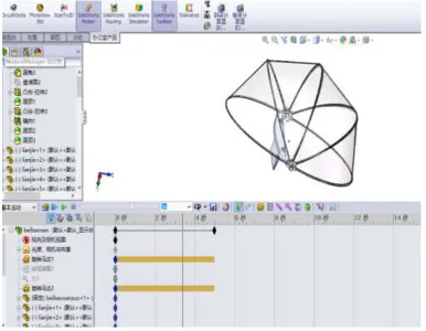
Motion Studies to achieve the mutual movement of two parts. This passage mainly operates the motion
simulation of opening the umbrella which is showed in Figure 9. Click ―Motion Studies‖ in the lower left corner
of the interface, add motor, select rotary parts and set the speed.
Figure 10 the motion simulation of remote boating umbrella
After the completion of installation, click the button to begin the calculation of the motion simulation.
If the color of the time bar which is used to computing time is buff, it shows the calculation is successful. If the
color is red, the calculation will be ended which proves that the model can’t achieve the motion simulation. At
this time, the design of computational process or the 3D model should be re – examined so as to modify the
mistakes. Then the motion simulation is repeatedly until it achieves the fixed action. Figure 10 shows the motion
IV.
THE RENDER DESIGN OF THE PRODUCT
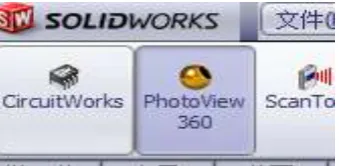
Photoview 360 isinteractionalsoftware that can achieve real-time ray tracing and global light rendering.
Since there are no need of complicated background and professional background knowledge, it is simple to learn
and operate and is very suitable for render design in industry. Its interface can connect seamlessly with
Solidworks, thus there is no need of re- allocation and update.
After umbrella modeling is achieved by using the Solidworks, click the interface button of
Photoview 360 in the tool bar of Solidworks. Then the model will be passed to Photoview 360, in which the
material of the parts will be fixed. After that the model can be updated into Photoview 360.
After the material parameters are fixed, rendering can begin. Figure 12 shows the design method of
rendering backpack umbrella. The generated effect drawing can be showed to customers and consumers. It can also be used to make package figure by combining with Solidworks Composer. What’s more, it also helps for the marketing and the writing of product manuals.
Figure 11 the interface of Photoview 360 in Solidworks
Figure 12 the drawing of rendering backpack umbrella
V.
THE GENERATION OF UMBRELLA SHOULDERING
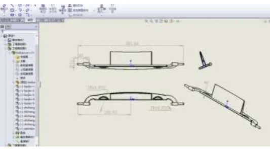
Fasten feature is the main basis of industrial production such as the design idea, manufacture,
debugging, usage and maintenance, etc. In general, Fasten feature is made up of view, dimension, technical
requirement and the specification of the title bar, etc. Solidworks supports GB and can establish national
standard of 2D drawing sheet. When Solidworks creates 2D fasten feature for parts and assembly, the feature of
the fully association of it enables the 3D model to interconnect with the fasten feature so that any modification
of parts or assembly will be promptly updated in the fasten feature, which will not only reduces repeat drawing,
and intercalating, the file format of ―dwg‖ and ―dxf‖ which are compatible with Autodesk CAD can be output to provide conveniences for communication about engineering.
Figure 13 2D manufacturing drawing of shouldering
VI.
THE REAL OBJECT OF CREATION OF BACKPACK UMBRELLA
According to the statistics in the drawing, select light aluminum product and firstly manufacture the
umbrella frame , then fix the transparent and plastic umbrella fabric on the shouldering, finally, such a
hands-free backpack umbrella is finished.
VII.
CONCLUSIONS
Recently more and more people like late-model umbrella, but designing this kind of complicated
backpack umbrella needs professional soft wares and advanced design method. As powerful 3D software under
the Windows system, Solidworks is easy to learn and use. It adopts top-down design method to improve the
speed of design, lower the error ratio as well as interposition checking and motion simulation, etc. Resourceful
plug-in units and secondary development will extend the function of Solidworks to make it more powerful.
Combining with the 3D rendering software of Key shot will be undoubtedly a good method to design umbrella.
The function of relational 2D fasten feature will improve the speed of drawing and make less mistakes. The
integrated application of these functions of Solidworks is of great importance to improve the overall level of
product design of our country and shorten the distance between our country and the developed countries.
REFERENCES
[1]. Youyong Jiang, Chun Xiang, Liangping Cui. The design and application for side-turn-over slap door by
the top-down method in Solid Works [J]. Coal Mine Machinery, 2011.32(2) : 229-231.
[2]. Qinghua Zhao, XinyuJia. A dynamic simulation of optimized plane four-bar mechanism based on Solid
Works [J]. Mechanical Design and Automation, 2007,(5) : 192-193.
[3]. Chunlan Liao. Research on dynamic simulation of umbrella mechanism based on SolidWorks Animator
[J]. Guangzhou Panyu Polytechnic, 2009. 8(1): 49-52.
[4]. Youyong Jiang, Chun Xiang, Liangping Cui. A study of two examples designed by top-down method in
the application of SolidWorks[J]. Guangzhou Chemical Industry. 2014.42(7):140—143.
[5]. Guoyan Chen, Xiaoli Guan. The simulation and analysis of structure movement based on SolidWorks Motion software[J]. ―Technology Wind‖ magazine, 2014, (1):125-125.
[6]. ZhengzhuJian. The application of SolidWorks software in industrial furnaces design[J]. Industrial
Furnace, 2014, 36(6).
SolidWorks[J]. ZhongZhou Coal, 2010, (5):44-44. DOI:10.3969/j.issn.1003-0506.2010.05.019.
[8]. Fan Wang, Yushu Chen. The application of top-down method in Hong Mu furniture based on
SolidWorks[J]. Furniture, 2014, (2):66-69.
[9]. JungangHao, Na Zhao. The application of keyshot in mechanical design software[J]. Computer
Development & Applications, 2013, (11):48-50. DOI:10.3969/j.issn.1003-5850.2013.11.016.
[10]. Xuelong Zhang, The investigation and analysis of umbrella design and manufacturing industry[J]. XU
Teli research: Journal of Changsha normal college, 2008, (2):51-55.
[11]. Sishuo Chen, Discussion on the education development of umbrella design[J]. Domestic and foreign
umbrella manufacture, 2012, (11):74-75.
[12]. Yang Huang, Dongbo Li, Xiang Shi. Methods for adding special marks and notes to engineering
drawings in SolidWorks[J]. Mechanical science and technology, 2003.
Corresponding author. Address:
School of Mechanical Engineering, ShanghaiUniversity of Engineering Science, No. 333, Longteng Road,
Songjiang District,Shanghai 201620, PR China. Tel.: +86 21 67791180; fax: +86 21 67791176.