Cleaning Process with Efficient Allocation
Scheme Improves Flash Memory Performance
Amir Rizaan Rahiman
Faculty of Computer Science and Information Technology, Universiti Putra Malaysia, Serdang, Selangor, MALAYSIA Email: [email protected]
Putra Sumari
School of Computer Sciences, Universiti Sains Malaysia, Penang, MALAYSIA Email: [email protected]
Abstract—Flash memory is a non-volatile storage device that offers lots of superiority features. However, it has two characteristics namely: 1) Out-place updating and 2) Cleaning process that affects its performance as an efficient storage sub-system. Both characteristics influence the access time requirement in enabling the continuity of data storing and updating. In this paper, we propose an efficient data allocation scheme that takes into account the data popularity as the main indicator in making the allocation decision. Then, we unveil the importance of the allocation scheme in the block cleaning algorithm process. The simulation studies have shown that the integration between the block cleaning algorithm and the proposed data allocation scheme has significant impact on the cleaning process performance in terms of the number of block erasure operation and the number of active block requirements.
Index Terms—flash memory, cleaning, algorithm, allocation, simulation
I. INTRODUCTION
Flash memory is a non-volatile storage device that offers superior features. Not only does it allow fast data access and has solid-state reliability, it is also small in size, light weight, emits zero noise, consumes less power and is more resistant to shock compared to other types of storage [1], [2], [3], [4], and [27]. It is popularly used in secured digital (SD), compact flash (CF) and personal computer memory cards international association (PCMCIA) cards. Flash memory is also extensively included in most electronic gadgets such MP3-players, PDAs (personal digital assistants), mobile phones and digital cameras, just to name a few.
However, two characteristics of flash memory namely 1) Out-place updating, and 2) Cleaning process, bring about several challenges concerning data management. Updating existing data by overwriting at the same physical location is strictly prohibited since it is a time consuming process. Therefore, the out-place policy was suggested [5], [6], and [7]. This policy works by storing
the updated data in a new location, while the original data is set as garbage1. However, when frequent updating occurs, the amounts of garbage increases and simultaneously decreases the amount of free space. Due to that problem, the cleaning process is necessary to ensure the continuity of data storing and updating. The cleaning process is commenced when the free size reaches a certain threshold of 20% – 35% of the total memory size, or it can also be commenced periodically [8]. In flash memory, the cleaning process is implemented by an erasing function and carried out on a block unit. However, the block may contain valid data currently being use by certain applications. Thus, any valid data residing in the block being cleaned must be copied out into other blocks. In particular, Douglis et al, [4] shown that the cleaning process and the block utilization level (i.e. the ratio between the valid data size and the block size) substantially impacts device access performance, energy consumption and block endurance.
Several block cleaning algorithms and data allocation schemes exist in the literature [6], [8], [9], [10], [13], [14], [18], [24], and [25]. The block cleaning algorithm determines the victim block to be cleaned with the lowest cleaning cost. We refer the cleaning cost to the access time required for valid data copying and block erasing. Conversely, data allocation deals with the problem of allotting the accessed data into a particular location in the memory array. According to Gal and Toledo [7], the right combination between the allocation scheme and the cleaning algorithm can improve flash memory cleaning process performance and also the block endurance. The main objective of the efficient data allocation in flash memory is to minimize the amount of active blocks required in realizing data storing and updating. When the amount of active blocks is minimized, the number of victim blocks needed during the cleaning process is reduced. However, the coordination between both processes in flash memory is not given much attention by most researchers. This paper proposes an allocation scheme called frequency-based (FB) scheme, and combines it with the existing block cleaning algorithms. By using a tracing file collected from real-world I/O
1Garbage is a dead data and shall not be used again.
systems as the workload and using the comprehensive simulations, we show that the amount of victim blocks can be reduced. Moreover, the proposed FB scheme performs better than the existing allocation scheme in terms of active block requirements, number of cleaning operations and cleaning cost.
The remainder of this paper is organized as follows. Section II discusses about the background of flash memory and related works. Section III provides detailed explanations about the proposed allocation scheme. The performance of the scheme is then evaluated in Section IV. Finally, this paper concludes with Section V.
II. BACKGROUND AND RELATED WORKS
There are two types of flash memory in the market: 1) NAND-flash, and 2) NOR-flash [11]. In this paper, we limit our focus to NAND-flash type and will simply refer to it as flash memory.
A. Flash memory characteristics
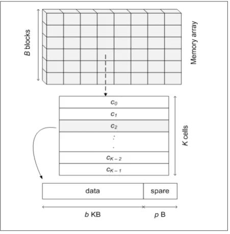
Flash memory is a block and cell units based storage device (Fig. 1). Data is stored in cell units where each cell is partitioned into two areas, namely, data and spare. The data area is used to store the actual data, while the spare area stores the assisting information for the data area (such as bad block identification, cell and block data structure, out-bound data and error-correction code (ECC)). A group of cells is called a block. According to the present production practices, the cell size is fixed from 512-Bytes to 4-Kilobytes, while the block size is between 4 and 128-Kilobytes [12].
Figure 1: Flash memory blocks and cells layout.
Flash memory offers three kinds of access functions, called, 1) Read, 2) Write/program, and 3) Erase with asymmetric access time (see Table I). The read and write functions are carried out in the cell units, while erase is performed in block units. Updating the existing data in flash memory is performed via out-place policy rather
than in-place updating. The updated data is stored into a new cell while its original cell is set as garbage. Therefore, as shown in Fig. 2, the cells in flash memory are separated into three categories namely, 1) Free, 2) Valid, and 3) Invalid. A free cell is an empty cell ready to store new or updated data. A valid cell contains the recent version of the data while an invalid cell contains an obsolete or “dead” data. As pointed out by Chou and Liu [13], blocks in the memory array can be categorized as either active or inactive. An active block refers to block that contains valid cells while blocks containing either free or invalid cells are referred to as inactive.
TABLE I.
FLASH MEMORY PROPERTIES
Notation Specification Value
p Cell size 2 KB
b Block size 128 KB
K Cells per block 64
B Number of blocks 8192
Rt Read access time in µs (10-6) 25 µs
Wt Write/program access time 200 µs
Et Erase access time in ms (10-3) 1.5 ms
Power consumption (Volts) 2.7 – 3.6 Size (h X w X d) (mm) 12 x 20 x 1.2
Noise ~ 0 db
Block endurance (erase and write) 100 K
B. Cleaning process in flash memory
As illustrated in Fig. 2, the cleaning process in flash memory is realized in three steps. Firstly, a victim block is determined. Then, all valid data residing in the block are identified and copied out into free cells in other blocks. Finally, the victim block is erased.
Figure 2: The three phases in cleaning process.
performed. Kawaguchi et al., [6] proposed cost-benefit (CB) algorithm where active block with a maximum value resulting from (1) is elected for cleaning.
((a x (1 – u))/2u) (1) The elapsed time from last data invalidation is
represented by a while u refers to block utilization level. Chiang and Chang [8] proposed the cost age time (CAT) algorithm to select victim blocks and the dynamic data clustering (DAC) reorganization technique to lessen number of block erasures. Active blocks that have minimum value resulting from (2) are chosen as the victim blocks.
(u/1 – u) x (1/a) x e (2) Then, the valid data are re-organized into new blocks
according to their updating frequency. Moreover, this algorithm considers the wear-leveling issue by considering the number of times the block has been erased (denoted by e) where blocks with fewest erasure counts have priority. Han et al. [17] proposed the costage time with age sort
(
CATA) algorithm that combines between the CAT and the age-sort algorithm which is inherited from the log-file structure (LFS) [10]. The blocks that maximize (3) are chosen for erasure.(1 – u/1 + u) x a x 1/e (3)
Kwon et al. [21] and [22] proposed the EF-Greedy and S-Greedy algorithms by extending the GR algorithm. The victim blocks are selected based on the GR algorithm and the valid data residing in the blocks are copied into new blocks using the predicted inter-update (PIU) time and the swapped-out time (SOT) information. Moreover, the wear-leveling policy is considered in both algorithms. C. Data allocation in flash memory
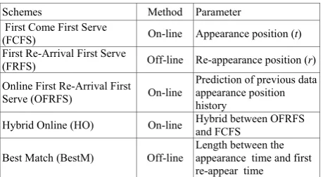
Data allocation in flash memory deals with the problem of deciding the block location due to out-place updating policy characteristic. The allocation scheme that requires lowest amount of active block will minimize the probability of blocks to be erased during the cleaning process. Several data allocation schemes with the aim of minimizing the amount of active blocks have been proposed in [13] and [14]. The details of the existing data allocation schemes are summarized in Table II.
TABLE II.
DATA ALLOCATION SCHEMES IN FLASH MEMORY
Schemes Method Parameter
First Come First Serve
(FCFS) On-line Appearance position (t) First Re-Arrival First Serve
(FRFS) Off-line Re-appearance position (r) Online First Re-Arrival First
Serve (OFRFS) On-line
Prediction of previous data appearance position history
Hybrid Online (HO) On-line Hybrid between OFRFS and FCFS
Best Match (BestM) Off-line
Length between the appearance time and first re-appear time
Two categories of data allocation schemes in flash memory are: 1) On-line, and 2) Off-line. The on-line scheme maps each data that appears in an access pattern (AP) into a free cell in a proper block at the time the data is accessed. The AP refers to a string of data involved in the storing and updating processes since both functions affect the cell state. On the contrary, the off-line scheme delays the allocation until all information in the AP is analyzed and the scheme results in minimum number of active blocks to be allocated. However, it needs knowledge of the entire information of the data in the AP. Thus, it is not suitable for time constraint applications. Moreover, the issue regarding the wear-leveling policy has been neglected in most allocation schemes. For instance, the block condition (such as the erasure count) is not taken into consideration when performing the allocation.
To increase the cleaning performance, however, there is no collusion between the data allocation scheme and the cleaning algorithm at the initial stage of the I/O operations. The data allocation schemes focus on minimizing the active block requirement by increasing the automatic cleaning process. Conversely, the cleaning algorithms try to reduce the semi-automatic cleaning. The automatic cleaning is being commenced when a particular active block turns into inactive state. Since, there is no valid data copying process, the block can be erased in the background during execution of the current operations (read or write) from/into the memory array. On the other hand, the semi-automatic cleaning is commenced when the memory array free spaces reach a certain threshold level. It is applied exclusively for the existing active blocks in the memory array with least utilization. Since the blocks contain valid data, the current operation to the memory array is temporarily halted. It is resuming back when the cleaning ended and the access time required is inconsistent. Equation (4) below shows the function used to clean n activeblocks with difference utilization level.
(1 – u/1 + u) x a x 1/Et (4) Due to these facts, we are motivated to combine the data
allocation scheme and block cleaning algorithm in order to guarantee the cleaning process performance. We propose an efficient data allocation step that considers the distribution pattern of the data in the AP and the block condition when performing the allocation.
III.EFFICIENT DATA ALLOCATION SCHEME IN FLASH MEMORY
A. Data accessing architecture in flash memory
Figure 3: Data allocation architecture in flash memory.
The allocation algorithm is the main part of the architecture. There are three procedures in the allocation algorithm, which are: 1) Interpreter, 2) Allocator, and 3) Cleaner. The interpreter elucidates the condition of the accessed data as being either popular or unpopular. The allocator is responsible for mapping the accessed data into a free cell in a particular block. Firstly, the allocator will generate the block ID. Then, it will map the accessed data into a first free cell in the block ID. After storing the data, the cell state where the data is stored is changed into valid state. For the data updating process, the updated data is stored into a new free cell while the cell containing the original data is set to an invalid state. The cleaner refers to the cleaning process that will be initiated automatically by the system software. If the block in the memory array turns from active to inactive, the block is erased automatically. Otherwise, the cleaning algorithm is invoked when a certain threshold pertaining to device free space is reached.
B. Frequency-based (FB) scheme
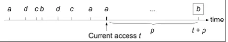
We present the FB scheme that takes into account the frequency of the data in the AP and the block circumstances when performing the allocation. The FB scheme is managed by the frequency() mechanism in the interpreter procedure. The appearance of data in the AP is autonomous because it is independently accessed by the users. Since its appearance is solely influenced by user access behaviors, the information regarding the particular data within a particular access interval in the AP is insufficient. Entirely depending on previous access information is not enough to establish the popularity of the data. The information gathered may become the final (data may appear only once in the AP). Besides, particular data may appear frequently at certain intervals within the AP (for instance, beginning, middle or ending parts of the AP).
For example, as illustrated in Fig. 4, data b only appears once at t and it may be the final appearance. However, after the p interval access, the data may appear again and again. Therefore, the accurate approach to determine the data popularity is by continuously calculating its appearance frequency throughout the AP. The reason is the current frequency can be used as an
estimate of the probability of specific data being accessed in the AP. Data with higher frequency is more likely to be accessed than data with lower frequency. Therefore, in the FB allocation scheme, the allocation for each data is according to its current appearance frequency. The data that has particular range of frequency are stored into different blocks in the memory array. The intuition of using the appearance frequency in storing the data is that we want to ensure particular blocks are not in the active state for the whole allocation process, which is a problem found in the FCFS scheme. We try to ensure that the blocks turn into inactive state as early as possible and they can be cleaned without the need to wait for the usual cleaning process. Therefore, when a particular turns into an inactive state (where it previous state is active) earlier and when the cleaning process is required, the number of active blocks involving in the cleaning process could be reduced. Hence, the cleaning cost required for copying the valid data could be minimized.
Figure 4: The inconstant data appearance in the AP.
Unlike the existing allocation schemes, firstly, the FB allocation scheme partitions the B blocks in the memory array into three clusters, namely, 1) Cold (denoted by Fcold), 2) Warm (denoted by Fwarm), and 3) Hot (denoted
by Fhot). The cold block specifically stores the first
appearance of each unique data in the AP while the hot block cluster stores the regularly appearing data. The remaining blocks are allocated for the warm cluster. We use the relative standard deviation of each data (denoted by R(pi)) to classify the frequency of the data in the AP
into the three main clusters. It is employed since it can forecast the regularity of the data that fall into a specific period of access time interval. Equation (5) shows the function that calculates the R(pi):
R(pi) = 100 x s(pi) / x(pi) (5) where s(pi) is the standard deviation of data pi while the
mean value is denoted by x(pi). The R value for each data
in the AP is expressed as a percentage representation. After obtaining the R(pi) values, the minimum and the
maximum among the evaluated values are determined in order to find the range of the access interval. The minimum value indicated by RMIN reveals the data that emerge frequently while the maximum value referred to as RMAX, reveals data that appear infrequently in the AP. Before that, the middle of the R(pi), denoted by Rmedian is
determined. Regularly appearing data are situated in the range 0 ≤ R(pi) < RMIN while the data that appears
irregularly fall in the range Rmedian≤R(pi) ≤RMAX. For the
middle regularity, the data relative standard deviation fall in the range RMIN≤R(pi) < Rmedian.
fractions; Fcold= 25%, Fhot = 55% and the remaining 20%
are allocated for Fwarm. The sequence of these partitions in
the memory array is in sequential order. In the FB scheme, we will allocate the first appearance of each unique data in the AP into the cold block cluster. For the second and the further appearance, the data is stored into the warm and hot block clusters according to their appearance frequency in the AP.
C. FB scheme illustration
Assume the AP is a, b, c, d, a, b, c, b, a, a, d, b, d, a, d, d, and number of blocks and cells (B and K are 4). The blocks are denoted as b0, b1, b2 and b3. A single block is
allocated for both Fcold and Fwarmwhile the remaining two
blocks are allocated for Fhot. Thus, the block ID for Fcold
and Fwarm is b0 and b1, respectively, while b2 and b3 are
allocated for Fhot. The first and the second appearance of
each unique data in the AP are allocated into the Fcoldand
Fwarm blocks. We assume the popular data with an
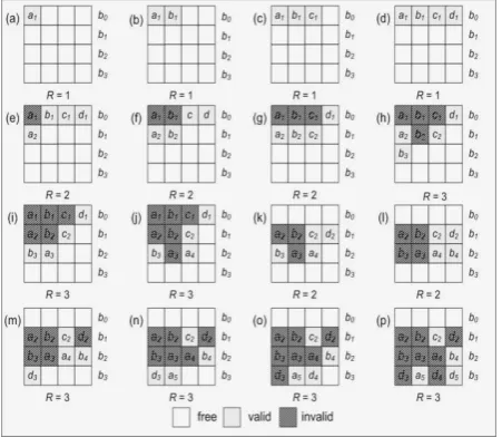
appearance frequency of three times or more (y ≥3). Fig. 5 gives an example of FB allocation scheme.
Figure 5: Example of the FB scheme where B and K are 4
From (a) to (p), data in the AP is allocated according to its present frequency. The first four data in the AP are the first appearance in the AP, therefore, from (a) to (d), the data are stored sequentially into the first free cell in block b0. Block b0 turns into active and it is inserted into
the list and the active block now is set to 1. In (e), data a re-appears for the second times and it is allocated into the first cell (c0) in block b1 while it first appearance in block
b0 is set to invalid. Since block b1 turns into active state,
active block now is increased to 2. Both in (f) and (g), the data appear for the second time and are stored into the free cell in block b1, while their first appearances are set
to invalid. In (h), data b reappears for the third time and is stored into the first free cell in the first block in the Fhot
cluster. Again, since block b2 turns into active state and
then inserted into the list, the active block is increased to 3. Next, when data d reappears for the second time in (k), it is stored into the first free cell in the available blocks in cluster Fwarm. At the moment, cell c3 in block b1 is free
and the data is stored into the cell. When its previous appearance (first appearance) in cell c3 at block b0
changes into invalid state, block b0 turns into inactive
state. The block is erased and its ID is removed from the active block list. Thus, the amount decreases to 2. In (m), the active block amount is increased back to 3 because block b3 is used to store the third appearance of data d in
the AP when block b2 is fully occupied. The block ID is
inserted into the list and the subsequent data in the AP, where their appearance is greater than 3 is stored sequentially in the block. At the end, the maximum number of active blocksrequired to store the data in the AP is 3.
IV. EXPERIMENTAL SETUP AND RESULT
A. Simuation model and parameters.
We evaluate the PB scheme by means of computer simulation. The performance of the PB scheme is compared with the existing allocation schemes FCFS, FRFS, OFRFS, HO and BestM in terms of the amount of active block requirement. This simulation model was programmed using the CSIM discrete-event simulation software [23]. The actual technical specifications of the experimental environment are summarized in the Table III.
TABLE III.
SIMULATION ENVIRONMENT AND EVALUATION PARAMETERS
Configuration Specification
Hardware
CPU: Intel Pentium IV (Dual Core) 1.6 GHz RAM : 4 Gbytes
HARD DISK: 120 Gbytes Operating System Microsoft Windows XP Professional
Simulation tools
CSIM 18
Programming tool: Borland C++ V. 5.02 Compiler: Borland C++ IDE (cppbc5) Components:
1. Processes
2. Facilities 3. Storages Flash memory
specification As shown in Table I.
The tracing file downloaded from Flash-Memory Research Group, National Taiwan University [26] as the workload in the experiments. The tracing file was recorded from a real system running I/O operations in disk sub-systems. The characteristic and the description of the tracing file are given in Table IV. The files were collected over 30 consecutive days using a personal computer running several general applications. The applications include Web browser (KKman, Firefox), P2P software, Windows Media Player, PowerPoint, Word, Acrobat Reader, and Outlook. In order to clarify the information displayed in Table IV, assume G = {1, 1, 4, 5, 2, 1, 2, 4, 5, 5} to be a sample of the AP. The size of sample (N) is 10, whereas the number of unique data (n) is equals to 4.
TABLE IV. TRACING FILE ATTRIBUTES
Data Sample Size (N)
Data (n)
Lowest frequency
Highest frequency
A set 1 45258 12948 1 4780
set 2 296182 103021 1 11228
B. Experiment results
The primary performance metric in this analysis is the amount of active blocks required in realizing the data storing and updating processes for the accessed data in the AP. The lowest amount of active blocks corresponds to a lower overhead for the cleaning process since the number of blocks involved in is minimized. Fig. 7 illustrates the evaluation result for the amount of active blocks required for the tracing file. The relationship between the access time of the data in the tracing files during the I/O operation and the average number of active block in realizing the storing and updating the data are presented in the figures.
As can be seen in the figures, the FCFS performs inferior as compared to other existing online allocation algorithms. On the other hand, the BestM results in the lowest amount of active blocks required for tracing all the files. For the tracing file, we found the average number of requested active blocks in realizing the updating process for FB scheme is lower than the existing online allocation algorithms, the FCFS, the OFRFS, and the HO. We use the frequency of appearance for each data that appears in the AP as the main measurement in determining the locations in the memory array.
In general, the FB scheme requires less active blocks than the probability-based (PB) allocation scheme, where the gap for both schemes does not see so obvious. The PB scheme allocates the accessed data in the AP according to the popularity factor. The popularity of the data in this scheme follows the Zipf’s distribution Law. For example, the gap between both algorithms is very small at the initial stage of the access time (almost similar). However, in the middle of the access, both algorithms consume more blocks than the HO at 12.01 pm (see Fig. 7a) and 12:56 pm (see Fig 7b). Then, the amount of active blocks begin to decrease when the access time increases and the gap between both FB and PB has become more obvious
at the end of the access pattern. On average, the FB requires approximately 8% less active blocks than PB scheme.
a) Set 1
b) Set 2
Figure 6: The average number of active blocks for different allocation schemes on Data A
C. PB scheme with block cleaning algorithms
We emphasize the importance of combining the FB allocation scheme with the existing cleaning algorithm in serving the accessed I/O operations. Efficient management between both procedures will achieve the goals of the cleaner in guaranteeing the performance of flash memory as storage sub-systems. The cleaning costs required for both conditions are totally different.
There are two categories of cleaning process in flash memory: 1) Automatic, and 2) Semi-automatic. The automatic cleaning is associated with the allocation scheme while the semi-automatic is employed by the block cleaning algorithm. Although the automatic cleaning requires constant access time (Et), the cost is
be cleaned during the semi-automatic process can be reduced. For that reason, the cleaning cost is reduced.
From the results shown in the Table V through X, several features can be summarized. First of all, both off-line allocation schemes FRFS and BestM require the largest amount of automatic cleaning compared to the online allocation schemes. For all block cleaning algorithms, both FRFS and BestM have similar amount of automatic and semi-automatic cleaning, approximately 85% and 12% on average. Since the allocation on these off-line schemes is decided after all accessed data are analyzed, the amount of active block involved when the cleaning process is initiated is smallest compared to the off-line allocation schemes.
TABLE V.
ALLOCATIONS WITH CAT CLEANING ALGORITHM
Allocation schemes Automatic cleaning performed (%)
Semi-automatic cleaning performed (%)
FCFS 44 56 OFRFS 47 53
HO 52 48
PB 56 44
FB 57 43
FRFS 84 16 BestM 86 14
TABLE VI.
ALLOCATIONS WITH CB CLEANING ALGORITHM
Allocation schemes Automatic cleaning performed (%)
Semi-automatic cleaning performed (%)
FCFS 43.5 56.5
OFRFS 45.5 54.5
HO 54.3 45.7
PB 58 42
FB 53.5 46.5
FRFS 86.5 13.5
BestM 86 14
TABLE VII.
ALLOCATION WITH GR CLEANING ALGORITHM
Allocation schemes Automatic cleaning performed (%)
Semi-automatic cleaning performed (%)
FCFS 42 58 OFRFS 47.6 52.4
HO 54 46
PB 55.6 44.4
FB 57.5 42.5
FRFS 85.67 14.33
BestM 87.5 12.5
TABLE VIII.
ALLOCATION WITH CATA CLEANING ALGORITHM
Allocation schemes Automatic cleaning performed (%)
Semi-automatic cleaning performed (%)
FCFS 44 56 OFRFS 46.5 53.5
HO 54 46
PB 58.5 41.5
FB 52.5 47.5
FRFS 86.8 13.2
BestM 89.5 10.5
TABLE IX.
ALLOCATION WITH EF-GR CLEANING ALGORITHM
Allocation schemes Automatic cleaning performed (%)
Semi-automatic cleaning performed (%)
FCFS 41 59 OFRFS 47.7 52.3
HO 55.5 44.5
PB 54.6 45.4
FB 58.9 41.1
FRFS 86.5 13.5
BestM 87.9 12.1
TABLE X.
ALLOCATIONS WITH S-GR CLEANING ALGORITHM
Allocation schemes Automatic cleaning performed (%)
Semi-automatic cleaning performed (%)
FCFS 43 57 OFRFS 49 51
HO 56.9 43.1
PB 55.6 44.4
FB 58.7 41.3
FRFS 85.1 14.9
BestM 86.5 13.5
There were slight increases and decreases between automatic and semi-automatic cleaning procedures in the on-line data allocation schemes, including our proposed FB scheme. Roughly, we can discover that there is a huge jump in the amount of semi-automatic cleaning for FCFS allocation scheme for all victim block selection algorithms. Among the on-line allocation schemes, the OFRFS records a little distinction between both cleaning procedures. The automatic erasure rate for PB and FB is between 52% and 59%, while for FCFS, OFRFS and HO, the erasure rate is between 38% - 44%, 45% – 48%, and 46% – 58%, respectively. Next, among the victim block selection algorithms, the CB algorithm requires the highest amount of block erasures while the EF-GR and S-GR algorithms (which are enhanced from the S-GR algorithm) record the lowest erasure amounts.
In all, the off-line allocation scheme requires the lowest erasure amount although the amount of automatic cleaning is the highest. Our proposed FB allocation schemes have shown that block erasures can be minimized and the cleaning cost could be reduced in comparison to the existing victim block selection algorithms. Hence, the analysis has shown and confirmed the efficient allocation scheme can minimized the cleaning cost requirement and increase the cleaning process performance.
V. CONCLUSION
In this paper, the proposed the FB allocation scheme is used to reduce the amount of active blocks in realizing the storing and updating of accessed data. Our scheme takes into account the data appearance frequency in AP while performing the allocation decision. The data with higher frequency are allocated into a similar cluster of blocks. By allocating the data into different cluster of blocks, the period for such block to be in the active state during the whole allocation process is reduced.The main idea of using this approach is to minimize the period of each block being in an active state. This can cause the block to become inactive earlier, thus minimizing the number of active blocks. We also showed the combination between data allocation scheme and the block cleaning algorithm. By combining both processes, there is significant improvement on the cleaning process performance. The evaluation performance has shown the relationship between both processes is necessary in guaranteeing flash memory efficiency as storage sub-systems. In this research, we perform the allocation together with the proposed cleaning process on a single memory chip. However, the memory chips can be packaged as a single storage device that can hold enormous capacity. Therefore, for the future research direction, we plan to extend the allocation scheme and the cleaning process among the multiple chips. By extending the studies, issues on striping can be utilized in order to increase the performance of the flash memory.
ACKNOWLEDGMENT
The authors wish to thank the reviewers for their constructive comments and suggestions helped to improve this paper. We would also like to thank University Putra Malaysia and University Sains Malaysia for providing technical assistance.
REFERENCES
[1] L. Chang, and T. Kuo, “An efficient management scheme for large-scale flash-memory storage systems,” Proceedings of the 2004 ACM Symposium on Applied Computing, SAC '04, Nicosia, Cyprus, pp. 862-868, 2004. [2] M. Breeuwsma, M.d. Jongh, C. Klaver, R.v.d. Knijff, and
M. Roeloffs, “Forensic data recovery from flash memory,” Journal of Small Scale Digital Device Forensics, vol. 1, pp. 1-17, June 2007.
[3] G. Lawton, “Improved flash memory grows in popularity,” Computer, vol. 39, pp. 16–18, January 2006. [4] F. Douglis, R. Caceres, F. Kaashoek, K. Li, B. Marsh, and
J.A. Tauber, “Storage alternatives for mobile computers,” Proc. 1st Symp. Operating Systems Design and Implementation (OSDI), Monterey, CA, USA, pp. 25 – 37, November 1994.
[5] Memory Technology Devices, http://www.linux-mtd.infradead.org/doc/nand.html.
[6] A. Kawaguchi, S. Nishioka, and H. Motoda, “A flash-memory based file system,” Proceedings of 1995 USENIX Annual Technical Conference, pp. 155-164, 1995.
[7] E. Gal and S. Toledo, “A transactions flash file system for microcontrollers,” Proceedings of the 2005 USENIX Annual Technical Conference, pp. 89-104, 2005.
[8] M.L. Chiang and R.C. Chang, “Cleaning policies in mobile computers using flash memory, “Journal of Systems and Software, vol. 48, pp. 213-231, November 1999.
[9] L.-P. Chang, “On efficient wear leveling for large-scale flash-memory storage systems,” Proceedings of the 2007 ACM symposium on Applied computing, Seoul, Korea, pp. 1126 -1130. 2007.
[10] M. Rosenblum and J. K. Ousterhout, “The design and implementation of a log-structured file system”, ACM Transactions on Computer Systems, vol. 10. pp. 26-52, 1992.
[11] NAND vs. NOR flash technology, http://www2.electronicproducts.com/NAND_vs_NOR_flas h_technology-article-FEBMSY1-FEB2002.aspx.
[12] K9K8G08U1A & K9F4G08U0A_Data Sheet for 512M Bit and 1G Bit NAND Flash Memory SAMSUNG.
[13] L.-F. Chou and P. Liu, “Efficient allocation algorithms for flash file systems,” 11th
International Conference on Parallel and Distribution Systems, pp. 634-641, 2005. [14] P. Liu, C.–H. Chuang, and J.–J. Wu, “Block-based
allocation algorithms for flash memory in embedded systems”, PaCT 2007, pp. 569–578, 2007.
[15] Chang, L.P. Kuo, T.W. and Lo, S. W. “Real-time garbage collection for flash-memory storage systems of real-time embedded systems,” ACM Transactions on Embedded Computing Systems, vol 3. pp. 837 – 863. 2004.
[16] Chang, Y.H. Hsieh, J.W. and Kuo, T.W. “Endurance enhancement of flash-memory storage systems: An efficient static wear leveling design,” Proceedings of 44th
ACM/IEEE Design Automation Conference (DAC 2007), pp. 212 – 217. 2007.
[17] L.-Z. Han, Y. Ryu, T.-S. Chung, M. Lee, and S. Hong, “An intelligent garbage collection algorithm for flash memory storages,” ICCSA 2006, pp. 1019-1027, 2006.
[18] Chang, L.P. and Kuo, T.W. “Efficient management for large-scale flash memory storage systems with resource conservation. ACM Transactions on Storage, vol. 1. pp. 381 – 418, 2005.
[19] Lee, C. Baek, S.H. and Park, K.H. “A hybrid flash file system based on NOR and NAND flash memories for embedded devices,” IEEE Transactions on Computers. vol. 57, no. 7, pp. 1002 – 1008, 2008.
[20] Wu, M. and Zwanepoel, W. “eNVy: a non-volatile, main memory storage system,” Proceedings of the 6th
International Conference on Architectural Support for Programming language and Operating Systems, Oct. 5 – 7, San Jose, California, pp. 86 –97, 1994.
[21] Kwon, O. Lee, J. and Koh, K. “EF-Greedy: a novel garbage collection policy for flash memory based embedded systems,” Proceedings of International Conference on Computational Science (ICCS 2007), Beijing, China, pp. 913 – 920, 2007.
[22] Kwon, O., Ryu, Y. and Koh, K. “An efficient garbage collection policy for flash memory based swap systems,” Proceedings of International Conference on Computer Science and Applications (ICCSA 2007), Oct. 24-26, pp. 213 – 223, 2007.
[23] CSIM Users’ Guide, http://www.cstp.umkc.edu/public/courses/cs522/notes/csim
_users_doc.pdf.
[24] Lee, S.W., Moon, B., Park, C., Kim, J.M. and Kim, S.W. “A case for flash memory SSD in enterprise database applications,” Proceedings of 28th ACM SIGMOD/PODS
[25] Jang, K.H. and Han, T.H. “Efficient garbage collection policy and block management method for NAND flash memory,” Proceedings of 2nd
International Conference on Mechanical and Electronics Engineering (ICMEE2010), Aug. 1-3, Kyoto, Japan. pp. V1-327-V1-331, 2010. [26] A trace of application executions over Windows XP,
http://newslab.csie.ntu.edu.tw/~flash/index.php?SelectedIt em=Traces.
[27] Caulfield, A., Grupp, L., and Swanson, S. “Gordon: An Improved Architecture for Data-Intensive Applications,” IEEE Micro, vol. 30, pp. 121 – 130, 2010.
A.R. Rahiman received the B.S degree in Computer Science from University Putra Malaysia (UPM) in 2000 and the M.Sc and Ph. D degrees in Computer Science from University Teknologi Malaysia (UTM), and University Sains Malaysia (USM), Malaysia in 2004 and 2011, respectively. Currently, he is lecturer at Faculty of Computer Science and Information Technology, UPM. His research interests include multimedia applications, e-learning solution, flash-based storage systems, and multimedia storage systems.
P. Sumari received the M.Sc. and Ph.D