Test Case Generation For Student Satellite
Soft-ware
Dinesha H A, Dr.V.K Agrawal
Information Science and Engineering, PESIT, Bangalore, India-560085 Information Science and Engineering, PESIT, Bangalore, India-560085 [email protected], [email protected]
ABSTRACT: PES Institute of Technology along with five other institutions is developing a student imaging satellite. This serves students as a platform to understand and work with advanced space technologies. In this student satellite, we use the approach of component-based software methodology to code and test the software components. In this methodology, all the components are developed as independent components and then are integrated under On Board Computer (OBC) software. OBC is a custom built board centered on the processor where student satellite software runs in the OBC. This paper reports the testing methodology we are using and test cases generation for On Board Computer software of student satellite. These test cases are used to assure the functional correctness of OBT software components of the student satellite.
Keywords :On Board Computer, Student Satellite, Test case generation, Functionality test case, Positive and negative test case;
1
I
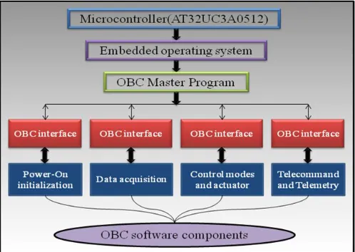
NTRODUCTIONThe primary objective of this student satellite is to stimulate the students in space technology, and to provide a learning oppor-tunity. It also empowers students with the skills to develop the satellite through different phases of analysis, design, fabrication and testing. The main scope of this student satellite is to capture the pictures of earth and downlinks to the ground station. It is planned to launch it in a polar sun synchronous orbit at an alti-tude of around 650 km and inclined at an angle of about 99º. The orbital period is around 90 minutes; eccentricity is about 0.001 and semi major axis of about 7000km. The hardware components used are: magnetic actuators, magnetometer, power sensors, sun sensors, thermistors, receiver, transmitter, camera and solar panels. The processor used here is UT32UC3A0512, which is of 32 bits, 512Kb memory and speed of 1.49 DMIPS (Dhrystone MIPS)/MHz which is sufficient enough for our mission [1]. Visual Studio is being used to devel-op OBC software. Programming language used here is Embed-ded C [2]. The OBC software system architecture depicted in figure 1 consists of OBC software components and interfaces. Here, the embedded operating system acts as an interface and co-ordinates between OBC master program and microcontroller. The components included in the OBC system architecture are: Power on initialization, data acquisition, control modes and ac-tuator, Telemetry and Telecommand. OBC master program calls and communicate with these OBC software components via OBC interface [3][4]. This paper is structured as follows: Initial-ly, the OBC hardware architecture is discussed in section II, and testing methodology is discussed in section III. The design of the test cases for OBC components are described in section IV. Section V concludes the paper with future enhancements.
Figure 1: OBC software system architecture
2
OBC
(O
NB
OARDC
OMPUTER)
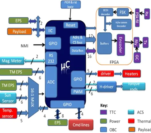
HARDWAREA
RCHITECTUREFigure 2: OBC Hardware Architecture
3
T
ESTINGM
ETHODOLOGYTesting is a process which checks the behavior and helps to identify the correctness, completeness of software compo-nents. Testing also determines whether there are any errors in the software. There are various general testing techniques. Among them most commonly used are: unit testing, black box testing, functional testing, integration testing, stress testing, security testing and acceptance testing. Unit testing tests the individual software components or modules. Black box testing is carried out based on the requirements and functionalities of software components. In functional testing, the software pro-gram or system under test is viewed as a “black box”, but func-tional testing is selection of test cases based on the require-ment or design specification of the software. Integration testing tests the integrated modules to verify combined functionality after integration of all the software components. Stress testing is stressed beyond its specifications to check how and when system will fail and also it is carried out under heavy load, like continuous input to system. Security testing is a technique to determine that an information system protects data and main-tains functionality as intended in the system. Acceptance Test-ing is done when the completed system is handed over from the developers to the users in order to give confidence that the system is working as intended. We saw so many testing techniques in figure 3, but this paper deals only with functionality test cases. Because, using functional testing we can know that the system behavior as it is expected and check whether all components are functioning properly. Testing methodology is designed to carry out testing in a procedural manner and it divides the testing life cycle into phases [5]. The testing methodology we are using to test OBC software components is shown in figure 4. Before testing any software, first we need to generate test cases, which describe an input and an expected output to determine whether the software components are working correctly. Our testing methodology includes functionality test cases. These test cases are written in a positive perception and also in a negative perception. So, test cases can be positive test cases or negative test cases. If the testing operation is performed using the valid data that is the actual input which gives the actual output, then this can be
done through positive test case. If the testing operation is performed using the invalid data and the expected output is an error, then this is done through negative test cases.
Figure 3: General Testing Techniques
Figure 4: Testing Methodology employed in OBC software
4
T
EST CASE GENERATION FOR THEOBC
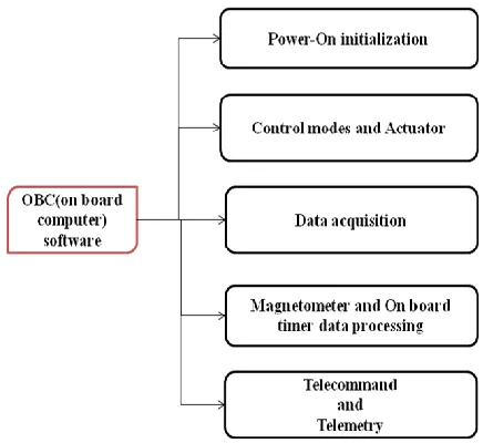
COMPONENTSSection below deals with the test cases for OBC software components. We are generating positive and negative test cases which are shown below: The OBC components are developed using the component-based development cycle. This is advantageous, because, we can start developing and testing each component independently. Figure 6 shows the student imaging satellite software components, namely, Power-on initialization, control modes and actuators, data acquisition, data processing, telecommand and telemetry. Shown below are the generation of functionality test cases with the perspective of generating positive test case and negative test case only to the components of Power-on initialization and data acquisition of OBC software
.
Power-on initialization: The power-on initialization module is called before execution goes, when system is powered on. Power-on initialization resets interrupt flags registers, clears output ports, initializes output ports, clears RAM memory, initializes global variables, configures components, and initializestelecommand & telemetry. Figure 6: OBC Software Components
Positive test cases for power-on initialization
Test case ID#
Test case description Test data Expected output Actual output Remarks
PPO1 To reset all the Interrupt Register
Registers old value
Interrupt flag values are reset to zero
Interrupt flag values are reset to zero
Success
PPO2
All out-put port pins of gpio should be cleared and initialized during power on initialization
Gpio out-put ports
Out-put port pins of gpio cleared
Out-put port pins of
gpio cleared Success
PPO3
To clear the memory of the RAM
RAM memory index
RAM memory is cleared to zero
RAM memory is
cleared to zero Success
PPO4
For initializing the components like, rtc,tc,usart,pwm,adc,twi
Usart pin,pwm channel,adc pin,pwm pin
All the specified components are initialized
All the specified components are initialized
Negative test cases for power-on initialization
Test case ID#
Test case description Test data Expected output Actual output Remarks
NPO1
If interrupt flags are not reset
Registers old value
Interrupt flag values are not reset, hence should not allow interrupts
Interrupt flag values are not reset, hence should not allow interrupts
failure
NPO2
If all out-put port pins of gpio are not cleared and initialized during power on initialization
Gpio out-put ports
While accessing should not get overwrite data or junk data through gpio ports
While accessing should not get overwrite data or junk data through gpio ports
failure
NPO3
If not clear the memory of the RAM
RAM memory index
RAM contains old garbage data which may mix up with new data
RAM contains old garbage data which may mix up with new data
failure
NPO4
If not initializing the components like rtc,tc,usart,pwm,adc,twi to access the data from analog ports
Usart pin,pwm channel,adc pin,pwm pin
Even though components are not initialized should be able to access data from analog ports
Even though components are not initialized should be able to access data from analog ports
failure
Positive test cases for data acquisition
Test case ID#
Test case description Test data Expected output Actual output Remarks
PDA1
Initializing ADC component by setting appropriate values to corresponding registers
Appropriate value for ADC component
Initialized ADC component with appropriate values to registers
Initialized ADC component with appropriate values to registers
Success
PDA2
Acquiring data from sun sensors, thermistors and power sensors for controlling and monitoring purpose
Data acquired from sun sensors, thermistors and power sensors
Analog data has been acquired from different hardwares
Analog data has been acquired from different hardwares
Success
PDA3
To convert the acquired data, enable the respective analog channel, then start converting
Particular analog channel has to be enabled
The data has been converted from analog to digital
The data has been converted from analog to digital
Success
PDA4
After completion of analog to digital data conversion, it is indicated by EOC(End of conversion)flag
Converted data EOC flag is set EOC flag is set Success
PDA5
Store the converted data
into particular address Address
Stored the converted data into a particular address
Stored the converted data into a particular address
Negative test cases for data acquisition
Test case ID#
Test case description Test data Expected output Actual output Remarks
NDA1
If not initializing ADC component with appropriate values to registers
No appropriate value for ADC
component
Not initialized ADC component should not allow further processing
Not initialized ADC component should not allow further processing
failure
NDA2
If data from sun sensors, thermistors and power sensors are not properly acquired
Data not acquired from hardwares
Analog data has not been acquired properly. This leads to data loss
Analog data has not been acquired properly this leads to data loss
failure
NDA3
To convert the acquired data ,first enable the respective analog channel then start converting
Particular analog channel is not enabled
The data conversion from analog to digital will not be allowed
The data conversion from analog to digital will not be allowed
failure
NDA4
If the completion of analog to digital data conversion is not indicated by EOC(End of conversion)flag
Converted data
EOC flag is not set hence cannot identify weather conversion is over or not
EOC flag is not set hence cannot identify weather conversion is over or not
failure
NDA5
Store the converted data into particular address
If no proper address is specified
Cannot store the converted data into a particular address
Cannot store the converted data into a particular address
failure
5.
C
ONCLUSION ANDF
UTUREE
NHANCEMENTSTest case generation the student imaging satellite has happened successfully. These test cases help to test the satellite in multiple scenarios. This facilitates testability, verification and correctness of the student satellite, which is made up of so many software components, but, here we generated test cases only for checking the functionalities of power-on initialization and data acquisition components. The future work deals with test case auto generation. considering the functionality of each and every software component. It also enables to write test cases to test the conditions, path of execution of the software components and this is also useful in doing integration testing.
A
CKNOWLEDGMENTOur sincere thanks to Prof. K N B Murthy, Principal and Prof. Shylaja S S, HOD, Department of Information Science and Engineering, PESIT, Bangalore, for their constant encourage-ment.
R
EFERENCES[1]. “Simplified Scheme for Data Acquisition in Student Imaging Satellite”, Mr.G.Raman Gouda, Mr.Dinesha H A, Prof.V.K Agrawal and Prof. R. Suguna, International Journal of Sci-entific & Engineering Research, Volume 3, Issue 3, March-2012, ISSN 2229-5518,1-6.
[2]. “AVR 8-bit and 32-bit Microcontroller - Atmel”, http://www.atmel.in/products/microcontrollers/avr/default.as px
[3]. “Systems Design of an Economical and General-Purpose
On-Board Computer for Low-Earth-Orbit Micro-Satellites”, Second International Conference on Electrical Engineering 25-26 March 2008 University of Engineering and Technolo-gy, Lahore, Muhammad Naeem Ayyaz, M. Riaz Suddle, Shakeel Zahid.
[4]. “Design of On-Board Software for an Experimental Satel-lite”, Alejandro Alonso, Emilio Salazar Juan A, de la Puente. [5]. Loubach, D.S.; Nobre, J.C.S.; da Cunha, A.M.; Dias, L.A.V.;
Nascimento, M.R.; Dos Santos, W.A.; , "Testing Critical Software: A Case Study for an Aerospace Application," 25th Digital Avionics Systems Conference, 2006 IEEE/AIAA , vol., no., pp.1-9, 15-19 Oct. 2006 doi:10.1109/DASC.2006.313741