Development of Digital Traffic Anti-Violation System
M. Nisha Angeline1, B. Aswini2, U. Devadharshini3, S. Gousalya4 and M. Aravind5
1Associate Professor, Department of ECE, Velalar College of Engineering and Technology, Tamilnadu. 2,3,4,5Final Year Student, Department of ECE, Velalar College of Engineering and Technology, Tamilnadu.
Article Received: 01 March 2018 Article Accepted: 09 April 2018 Article Published: 28 April 2018
1. INTRODUCTION
The main objective is to design a digital machine for avoiding traffic violation, monitoring and managing the
databases of crimes related to traffic rules and obtaining the original details about the vehicle digitally using
android application and RFID . RFID readers contain all the information about the vehicle and the owner. RFID
readers are devices that power & communicate wirelessly with tags. RFID deliver tag data to the operating system
software. RFID is an acronym for “radio-frequency identification” and refers to a technology whereby digital data
encoded in RFID tags or smart labels (defined below) are captured by a reader via radio waves. RFID is similar to
bar coding in that data from a tag or label are captured by a device that stores the data in a database. RFID, however,
has several advantages over systems that use barcode asset tracking software.
The most notable is that RFID tag data can be read outside the line-of-sight, whereas barcodes must be aligned with
an optical scanner .Advantages of this system is Traffic monitoring can be controlled, Corruption can be avoided,
Crime records will be maintained properly, Public receive the acknowledgement message immediately. It is used
for digital transaction of fine amount using android application and to control traffic violation act by avoiding
corruption. It is used to identify vehicle and owner information and to monitor the duty time of traffic police
through the time of login and logout.
2. EXISTING SYSTEM
In our state, for any traffic violation act the fine is acknowledged only through manual receipts which might be
fake in most of the cases. In Some other states, the billing is done with the electronic machine as shown in fig.1,
which has no any storage facility, so that the database cannot be maintained .The complete information about the
vehicle is checked just manually. Nowadays the charged fine are paid in the court. As there are many pending cases
in the court, the fine may not be received in proper time.
A B S T R A C T
For any traffic violation act the fine is acknowledged only through manual receipts which might be fake in most of the cases. The complete information about the vehicle is checked just manually. Nowadays the charged fine are paid in the court. As there are many pending cases in the court, the fine may not be received in proper time. Corruption may occur by receiving the fine without charging the crime. Using android application, the fine can be charged digitally as per the government tariff and the database is linked with government website. Using Radio Frequency Identification (RFID), the vehicles can be automatically identified using electromagnetic fields. The information about the vehicle and the owner can be viewed through RFID reader. RFID uses an attached antenna to capture data from tags. In this work, RFID reader reads the data from the RFID tag fixed in the vehicle. Then those data are transferred to the PIC microcontroller which is processed in the android application.
Fig.1.Fine collection machine
3. PROPOSED SYSTEM
Using android application, the fine can be charged digitally as per the government tariff and the database is
maintained and linked with government website. Using Radio Frequency Identification (RFID), the vehicles can be
automatically identified using electromagnetic fields. RFID readers contain all the information about the vehicles
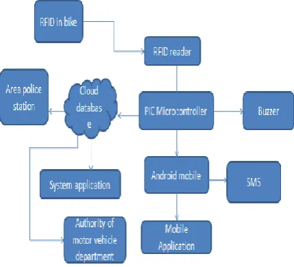
and the owner. The block of proposed system is shown in fig.2
Fig .2. Proposed System Block Diagram
3.1. RFID READER
Radio Frequency Identification (RFID) uses radio frequency signals to automatically identify objects. RFID
readers which are shown in fig .3, are devices that power and communicate wirelessly with tags. It delivers tag data
to the operating system software. The digital data encoded in the RFID tags or smart labels are captured by a reader
via radio waves as shown in fig.4. RFID is similar to bar coding in that data from a tag or label are captured by a
must be aligned with an optical scanner.
Fig.3.RFID card reader
Fig .4.How does RFID works
3.2. PIC MICROCONTROLLER
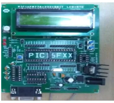
The PIC16F8X family of devices are CMOS microcontrollers consisting of the PIC16F83, PIC16C83, PIC16F84,
PIC16C84 and PIC16LF8X types(fig.5). CMOS technology offers a number of advantages over other
technologies. For example, CMOS circuits consume very little power, operate over quiet wide voltage range are
quiet forgiving of bad layout and electrical noise. The PIC16X8X is available in an 18 pin IC package. The IC
consists of two pins for the power supply, two pins for the oscillator, OSC1 and OSC2, a pin for the master reset
clear line MCLR and 13 pins for input/output ports, RA0 to RA4 and RB0 to RB7. The pin diagram of PIC
microcontroller is shown in fig.6.
Fig.6.Pin diagram of PIC16F8XX
3.3. USB2 SERIAL CONTROLLER
In telecommunications, RS-232(Recommended standard 232)is the traditional name for a series of standards for
serial binary single-ended data and control signals between DTE(Data terminal Equipment) and a DCE (Data
Circuit-terminating Equipment). It is commonly used in computer serial ports. An RS-232 port was once a standard
feature of a personal computer for connections to modems, printers, mice, data storage, un-interruptible power
supplies and other peripheral devices. RS-232 has mostly been replaced in personal computers by USB for local
communications. Compared with RS-232, USB is faster, uses lower voltages, and has connectors that are simpler to
connect and use. Serial ports with RS-232 are commonly used to communicate to headless systems such as servers,
where no monitors or keyboard is installed, during boot when operating system is not working yet and therefore no
network connection is possible. An RS-232 serial port can communicate to some embedded systems such as routers
as an alternative to network mode of monitoring.
3.4. BUZZER
A buzzer or beeper is an audio signalling device, which may be mechanical, electromechanical or piezoelectric.
Typical uses of buzzers and beepers include alarm devices, timers and confirmation of user input such as a mouse
click or keystroke. Buzzer is an integrated structure of electronic transducers, DC power supply, widely used in
computers, printers, copiers, alarms, electronics, automotive electronic equipment, telephones, timers and other
electronic products for sound devices. Active buzzer 5V Rated power can be directly connected to a continuous
sound, this section dedicated sensor expansion module and the board in combination, can complete a simple circuit
design, to "plug and play".
Specifications:
1. On-board passive buzzer
4. Working voltage: 5V
5. Board size:22(mm)x12(mm)
3.5. CCS COMPILER
Intelligent and highly optimized CCS C compilers contain standard C operators and Built-in function libraries that
are specific to PIC registers, providing developers with a powerful tool for accessing device hardware features from
C language level. Standard C pre processors, operators and statements can be combined with hardware specific
directive and CCS provides built-in functions and example libraries to quickly develop applications incorporating
leading edge technologies such as capacitive touch, wireless and wired communication, motion and motor control
and energy management.
3.6. PROTEUS
The Proteus design suite is wholly unique in offering the ability to co-simulate both high and low-level
micro-controller code in the context of a mixed mode SPICE circuit modulation. Proteus Virtual System
Modelling (VSM) improves efficiency, quality and flexibility throughout the design process. Proteus VSM is
possible to develop and test designs before a physical prototype is constructed. The simulation takes place in real
time. Proteus VSM also provides extensive debugging facilities including breakpoints, single stepping and variable
display for both assembly code and high level language source.
3.7. ANDROID
Android is Linux-based operating system designed primarily for touch screen mobile devices such as smart phones
and tablet computers. Initially developed by Android, Inc., which Google backed financially and later brought in
2005, Android was unveiled in 2007 along with founding of Open Handset Alliance: a consortium of hardware,
software, and telecommunication companies devoted to advancing open standards for mobile devices.
Android is open source and Google releases the code under the Apache License. The Open-source code and
permissive licensing allows the software to be freely modified and distributed by device manufacturers, wireless
carriers and enthusiast developers. Additionally, Android has a large community of developers writing applications
("apps") that extend the functionality of devices, written primarily in a customized version of the Java
programming language.
Applications are developed in the Java programming language using the Android software development kit (SDK).
The SDK includes a comprehensive set of development tool, including a debugger, software libraries, a handset
emulator based on QEMU, documentation, sample code and tutorials. The officially supported integrated
development environment (IDE) is eclipse using the Android Development Tools(ADT) plug in. Other
Google App Inventor, a visual environment for novice programmers, and various cross platform mobile web
applications frameworks.
4. RESULTS AND DISCUSSION
Thus the computerized view of digital fine collection using RFID and android application is shown in below
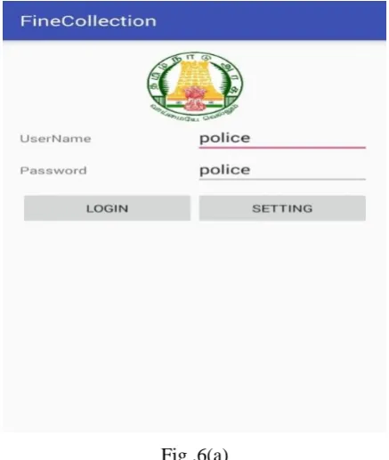
figures. The traffic police can login this application by entering the username and password as shown in fig.6(a)
Fig .6(a)
The required details about the fine collection, vehicle detail, payment backlogs, complain backlogs can be viewed
is shown in fig.6(b).
Thus the information about the vehicle, license period, and registration certificate has displayed as shown in
fig.6(c).
Fig.6(c)
The overall collection of a day by the particular traffic police can be consolidated and viewed as shown in fig.6(d).
Fig.6(d)
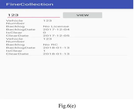
Fig.6(e)
Fig 6: Computerized view of digital fine collection
5. CONCLUSION
The proposal of this paper is to control the traffic violation and to maintain the records in a database thereby
avoiding corruption. In future, the backlogs in any cases can be verified.
REFERENCES
[1] T.Kumar, R.Sachan, D.S.Kushwaha., (2015),"Smart City Traffic Management and Surveillance System
For Indian Scenario". In Proceedings of International Conference on Recent Advances in Mathematics,
Statistics and Computer Science (ICRAMSCS).
[2] R.M.John, F.Finky, N.Joe, A.Alwyn, D.Ancy, and K.J.Jinesh (2014),"Smart Public Transport System", In
Embedded Systems (ICES),International Conference on pp.160-170.IEEE,2014.
[3] Vuza D.T.; Frosch R. ;Koeberl H. ; Vladescu M.,"A current-driven RFID reader with automatic antenna
tuning",2011 IEEE 17th International Symposium for Design And Technology in Electronic Packaging
(SIITME), DOI:10.1109/SIITME.2011.6102740, publication Year: 2011, page(s):299-304,2011.
[4] Dhawade Pooja J, Lathkar Y.V, Date Purushottam B, "Smart Home Using Android Application", IJRET:
International Journal of Research in Engineering and Technology, Volume: 3(4),pp.365-367, April 2014.
[5] Chaitanya R, Thiyagarajan M., "Finite State Machine model for Web service Access", Jokull Journal,
Vol.65, Issue No.4, April 2015.
[6] Yongqing Fu, Chun Zhang, and Jingchao Wang. A research on denial of service attack in passive RFID
system. In Anti-Counterfeiting Security and Identification in Communication (ASID), 2010 International
Conference on pages 24-28, 2010.
[7] T.Halevi, Haoyu Li, Di Ma, N. Saxena, J. Voris and Tuo Xiang. Context-aware defences to RFID
unauthorized reading and relay attacks. Emerging topics in Computing IEEE Transactions