Application of Semi-Perforated V-gutter
Flameholders in Heat-Generating Systems for
Autonomous Building Heating
Dias Raybekovich Umyshev, Issakhan Amantaevich Zholbaryssov, Nina Gavrilovna Borissova, Abay
Muhamediyarovich Dostiyarov, Nassipkul Kasszhanovna Dyussembekova, Olga Aleksandrovna Stepanova,
Musakul Elekenovich Tumanov
Abstract— This paper presents the results of experimental and numerical studies of semi-perforated V-gutter flameholders. The high-precision laboratory equipment helped to make measurements of the emission of nitrogen oxides, the exhaust gas temperature, the values of lean blowout and the parameters for calculating combustion efficiency. The analysis showed that fuel supply from the bottom part of the V-gutter makes it possible to burn the fuel more efficiently and allows for a wider combustion range. However, there is a higher emission of nitrogen oxides in the context of such fuel supply. In addition, fuel supply from the bottom part of the V-gutter provides a high exhaust gas temperature, which is very important when designing heat-generating systems. The numerical simulation of the combustion process behind V-gutter flameholders confirms the research findings and shows the physical side of combustion behind the recirculation zones of V-gutter flameholders. On the basis of microflame elements in the form of semi-perforated V-gutter flameholders, the authors present the model of a heat generator that can be used as a heat source for autonomous air heating of residential and office buildings, such as institutions of higher education. The authors also provide the performance calculations depending on the fuel consumption rate and the outside air temperature. The calculations confirm the high performance and reliability of the proposed circuit in all weather conditions of the heating season.
Index Term— heating, heat-generating systems, heat treatment, V-gutter flameholder.
I. INTRODUCTION
One of the most attractive ways to reduce the formation of nitrogen oxides (NOx) and to improve the efficiency of the combustion process is to use bluff bodies in the form of V-gutters [1]-[16]. V-gutter flameholders are one of the elements of microflame devices. The flame tube head of microflame combustion chambers consists of microflame devices. Due to the fact that the stabilization and combustion of the air-fuel mixture is determined by the recirculation zone (RZ) behind V-gutters, NOx formation depends on the quality of air-fuel mixing, the temperature in the combustion zone and the residence time of combustion products in the high-temperature zone. The optimal selection of the expansion angle and the wall length as well as possible perforations may provide an optimal RZ value. The optimal RZ value provides a relatively low average temperature in the combustion zone, short residence time of combusted gases as well as adequate mixing [3].
The combustion processes in V-gutter flameholders are considered in a number of studies. The analysis of research on the lean blowout process behind V-gutter flameholders
that the lean blowout process in recirculating flames takes longer residence time in the recirculation zone [1]. The turbulent premixed fuel combusting behind bluff bodies has been studied since the early 50-ies of the last century [2]-[4]. However, the flameholding processes have been insufficiently described.
Another research area is the study of the impact of bluff bodies on the process of stabilization of various fuels. The investigation of the impact of the liquid accompanying gas with addition of hydrogen on the gas temperature and NOx emissions has shown that an increase in the amount of hydrogen reduces the flame length [5]. The reduction of nitrogen oxides was also demonstrated when increasing the coefficient of congestion and the molar mass of hydrogen. Newbold et al. [6] experimentally studied the effect of using bluff stabilizers in diffusion flames. A strong recirculation zone of stabilizers reduced the formation of nitrogen oxides, but increased the formation of carbonic oxides. Studying the combustion simulation of CH4/H2, Kim and Huh [7] proved that radiation losses when using V-gutter flameholders have little impact on the emissions of nitrogen oxides at the diffusion combustion and flame.
Of particular interest is the study of the jet-stabilizer combustion process behind V-gutter flameholders [8]-[12]. Such devices as well as the combustion processes on their basis were studied by the researchers of Kiev Polytechnic University. Summarizing their works, one can say that this method helps to ensure high combustion stability, low NOx emissions and high combustion efficiency. However, these researchers have not studied perforated and semi- perforated V-gutter flameholders.
Aiwu Fan et al. [13]-[16] conducted a deep study of the processes of combustion, stabilization and heat exchange behind bluff bodies. It has been proven that the process of stabilization is significantly dependent on the recirculation zones formed behind V-gutter flameholders. The process of the RZ formation is influenced by a number of factors such as fuel consumption, air velocity and others. The experiments have shown that an increase in the size of flameholders as well as the concentration of hydrogen in the air-fuel mixture leads to an increase in combustion stability.
conditions are established. Such a region has a high temperature due to the conjugate heat exchange between the heat-conducting bluff body and the hot reacting flow.
One of the problems facing the power industry is the heating system. The core of this problem is the place of generating and the method of distributing the heat-transfer fluid of the necessary parameters in the required amounts [19], [20]. In this regard, the current trend in the development of heating systems is to improve the reliability and efficiency of the existing centralized systems as well as to use the autonomous heating systems to the full extent.
The introduction of the autonomous heating system provides the solution to the following problems:
- Provision of heating supply in the construction of new residential areas with no access to heating networks;
- The possibility to independently regulate the consumption of heat, and hence the cost of heating and hot-water [21].
Currently, gas forced-air heating has gained widespread use. A distinctive characteristic of the heating system is that buildings can be quickly warmed up. The process of implementing such a system can be explained by the circulation of hot and warm air flows. To maximize the proper implementation of this process, it is necessary to establish such a facility as a heat generator. Heat generators are also one of the application scenarios of V-gutter flameholders, in addition to heat engines - gas turbines. They are regarded as the devices, which allow the chemical energy of fuel to be converted into the heat of the heat-transfer fluid. Based on the analysis of materials, the authors found it necessary to study the processes of combustion behind V-gutter flameholders as applied to heat generators, which could be used as autonomous heating sources in the buildings of higher education institutions.
II. MATERIALS AND METHODS
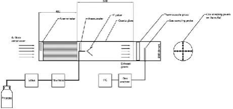
The schematic diagram of the experimental setup is shown in Figure 1a and its general view is presented in Figure 1b.The experimental setup consists of the fuel supply system - a compressor, Ø16 mm tubes for the air flow stabilization (behind the compressor), and anemometers for calculating the air flow rate. Behind stabilization tubes there is a quartz Ø150 mm tube. At the output of the setup there is a Cr/Al thermocouple and a tube for making measurements of the gas analyzer, which in turn is connected to a personal computer. For the experiment, the high-precision equipment was chosen, and the accuracy of measurements on each device was less than 3%. It should also be noted that in order to obtain more accurate figures, additional measurements were carried out with the help of a second gas analyzer. In addition, to confirm the figures received, some random measurements were checked by the chemo-luminescent method.
The following condition was used to measure nitrogen oxides, combustion temperature and efficiency: the fuel consumption rate for all modes was constant and equaled 1.2 kg/hr. For changing the excess air values (equivalence ratio) φ, the air flow rate was changed from 2 m/s to 10 m/s. The equivalence ratio was calculated by the following equation:
where 5 is the equivalent value for propane (calculated from the formula of combustion), – the fuel flow rate, - the air flow rate.
The following formula was used to determine the efficiency of combustion:
( ) ( ) ( ) ( )
During the analysis of the lean blowout process, the experiment was conducted as follows: for each mode a specific air flow rate was set in the range of 2-10 m/s, in increments of 2 m/s, and the fuel flow rate was defined as the maximum. After ensuring a stable combustion, the fuel flow rate was reduced to a visual extinction of the flame. After that, the value of the fuel flow-rate meter was recorded. The value of the lean fuel blowout process was also defined by equation 1.
Fig. 1a. The schematic diagram of the experimental setup
Fig. 1b. General view of the experimental setup. 1 – the air supply system, 2 – V-gutter flameholders, 3 – the quartz tube
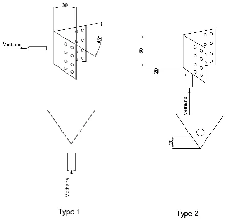
Fig. 2. General view of the V-gutter and the fuel supply system
III. RESULTS AND DISCUSSION
A. NOx formation
Figure 1 shows the dependence of NOx emissions on the equivalence ratio φ. As seen from this figure, there is no significant difference between fuel supply to the V-gutter and under the V-gutter. However, it should be taken into account that the emission of nitrogen oxides will have a considerable difference if the scale of the setup is increased.
However, despite the proximity of the values, it is safe to say that fuel supply to the V-gutter makes it possible to receive slightly smaller values of NOx emissions. Lower emission figures indicate better fuel-air mixing. This is due to the following reasons: 1) the recirculation zone is formed around the V-gutter flameholder due to the pressure gradient that is why the fuel flowing around the V-gutter is sucked into the inner zone of the V-gutter along with the air. This fact leads to good mixing and a reduction in "rich" zones in the inner zone of the V-gutter; 2) perforations on the edges of the V-gutter allow part of the fuel to penetrate into the inner zone of the V-gutter. This ensures a stable combustion and good fuel mixing.
When the fuel is supplied from the bottom (type 2), several processes are taking place. Firstly, the fuel mixes with the air directly in the recirculation zone where combustion occurs. This reduces the time required for complete fuel-air mixing. Secondly, the fuel is supplied vertically, which increases the residence time of gases in the combustion zone. The sum of these factors leads to the relatively overestimated figures of NOx formation.
Considering that V-gutter flameholders are taken as the basis for heat generator development, NOx are an important indicator, since there is a constant fight against harmful emissions.
Fig. 3. Dependence of NOx emissions on the equivalence ratio
B. Temperature
One of the most important indicators of the heat generator is the temperature at the output of the setup, because the volume of the heated air depends on the temperature of gases. As can be seen from Figure 4, the highest temperature is typical for the second type of fuel supply. This explains slightly high values of NOx emissions. However, it can be seen that at the greatest equivalence ratio of φ=0.5 the emission of nitrogen oxides is higher in the first type of fuel supply.
A higher temperature when using the second type of fuel supply is explained as follows: the fuel, supplied from the bottom side of the V-gutter, enters the recirculation zone at a right angle, i.e. perpendicularly, which results in a reduction of the residence time of gases in the combustion zone, because the fuel residence time is less compared to the first supply type. For this reason, the local zones with a "rich" fuel concentration are being formed, which leads to the formation of high-temperature zones. Such zones increase the overall temperature of the flame, as shown in Figure 4.
Fig. 4. Dependence of the exhaust gas temperature on the equivalence ratio
C. Combustion efficiency
In terms of fuel and energy conservation, the efficiency of combustion plays a significant role. Given that all microflame devices ensure high combustion efficiency in a wide range of combustion, it is necessary to compare the maximum achievable values. The dependence of combustion efficiency on the equivalence ratio is shown in Figure 5. It
0 0.5 1 1.5 2 2.5 3 3.5 4 4.5
0 0.2 0.4 0.6
N
O
x
[1
5
%O
2
]
φ
Type 1 Type 2
300 350 400 450 500 550 600 650
0 0.2 0.4 0.6
T
em
p
er
atu
re,
K
φ
advantages. However, it should be taken into account that the difference between the two types of fuel supply is not more than 1-2%. A higher combustion efficiency is ensured by the characteristic of fuel supply. In this form, the fuel residence time in the combustion zone is longer, which increases the efficiency of combustion.
It should be noted that the maximum combustion efficiency is achieved at a value of φ=0.3 for all types of fuel supply. This fact indicates that at a given fuel flow rate, there is an optimal ratio of the fuel-air mixture and the recirculation zone. A low combustion efficiency of up to φ=0.3 is explained by the lack of air in the recirculation zones. And at φ=0.3, there is a strong air flow, which increases fuel entrainment.
Fig. 5. Dependence of combustion efficiency on the equivalence ratio
D. Lean blowout
Lean blowout is very important in terms of ensuring a continuous operation of the heat generator and heat supply. As seen from Figure 6, the range of blowout decreases with increasing the air flow rate (velocity). However, the second type of fuel supply has some advantages. Ensuring an uninterrupted combustion is important and shows the reliability of the equipment.
Fuel lean blowout in the first type occurs by reducing the contact time of the combusted fuel and the fresh fuel-air mixture. In addition, a secondary factor is an increase in the recirculation zone by increasing air velocity. The expansion of the recirculation zone leads to a larger air capture in the combustion zone and the reduction in fuel concentration. The sum of these factors leads to fuel lean blowout.
In the second type, the values of lean blowout are lower due to peculiar fuel supply. As mentioned above, this fuel supply type is characterized by an insufficient fuel mixing, which is a major factor resulting in a lower flame stabilization.
Fig. 6. Dependence of lean blowout on the equivalence ratio
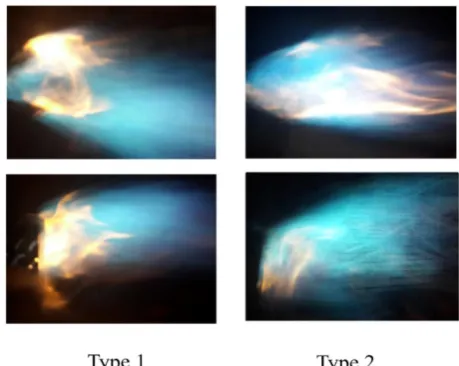
Figure 7 shows some photographs taken during combustion behind V-gutter flameholders. These photos were taken at φ=0.3. They show that V-gutters with fuel supply from the bottom (type 2) have a lower flame luminosity. This indicates a higher combustion efficiency. Combustion efficiency is provided by a longer residence time of gases in the combustion zone due to peculiar fuel supply. The recirculation zone also plays an important role. In the context of profile shooting it can be seen that the flame near the V-gutter with fuel supply from the bottom (type 2) is slightly higher due to the characteristic of fuel supply.
Fuel supply to the V-gutter symmetry axis (type 1) has a greater luminosity. This indicates a slightly lower combustion efficiency, as evidenced by the resulting dependence of combustion efficiency on the equivalence ratio. Combustion efficiency is also influenced by the sufficiency of oxidizing agents and the residence time of gases in the combustion zone. But it is necessary to take into account that these factors also affect the formation of nitrogen oxides. In this case, it can be said that the minimum residence time of gases in the combustion zone increases the formation of nitrogen oxides and leads to some reduction in combustion efficiency.
Fig. 7. Combustion process behind V-gutter flameholders
94.5 95 95.5 96 96.5 97 97.5 98 98.5 99 99.5
0 0.2 0.4 0.6
C
o
m
b
u
stio
n
ef
ficien
cy
,
%
φ
Type 1 Type 2
0 2 4 6 8 10 12
0 0.1 0.2 0.3
A
ir
v
elo
cit
y
,
m
/s
φLBO
E. Numerical simulation
To confirm the results obtained in the experiment, the authors carried out the numerical simulation of the combustion process behind V-gutter flameholders using ANSYS Fluent 13.0 software [22], [23]. The recommended turbulence model was used [22], [23] – k-ε realizable with the function of enhanced wall treatment adjusted for the curvature of streamlines, allowing for more efficient estimation of the gas-dynamic indicators of heavily swirled reacting flows. According to [22], [23], a grid was selected from tetrahedra and consisted of 800,000 elements. The initial conditions for numerical simulation were similar to those in the experiment.
To investigate how a flameholder angle affects flow velocity, a simple CFD analysis was carried out for all cases. For computation, a commercial CFD package, ANSYS FLUENT Ver. 13, was used with appropriate assumptions. A total of 800,000 tetra mesh elements were generated within the calculation domain. For turbulent modeling, realizable k-ε model with enhanced wall treatment was chosen. Non-premixed combustion model was chosen for combustion modeling. The air flow was 127 kg/s and the fuel flow was equal to 1 kg/s. The cross section of the numerical model is schematically shown in Figure 8.
Fig. 8. Cross section of the numerical model
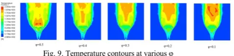
Figure 9 shows the temperature contours of the combustion process behind V-gutter flameholders. The zone of reverse flows, in which the combustion process takes place, is being formed behind V-gutter flameholders. This is particularly evident at a relatively "rich" fuel concentration of φ=0.5. An increase in the air flow rate (velocity) leads to the narrowing of the flame and the emergence of the high-temperature zone in the center of the flame. This is particularly evident at φ=0.1.
Fig. 9. Temperature contours at various φ
F. Independent building heating on the basis of microflame elements
Based on the experiments conducted, the authors propose a system of the autonomous air heating of buildings of higher education institutions on the basis of heat generators with microflame V-gutter flameholders. The heat generator circuit is presented in Figure 10. Based on the above experiment, it was demonstrated that semi-perforated
V-gutter flameholders have a number of advantages, which can be used for building heating. These include high combustion efficiency, uniform temperature distribution over the cross section, low NOx emissions. All these advantages play an important role in energy conservation and heat maintenance of buildings of higher educational institutions. This type of heat generators can also be used for hot water supply systems.
The proposed heat generator operates as follows. The fuel is supplied to gutter flameholders, namely to the V-gutter symmetry axis. After being combusted, combustion products move along the gas duct. From the outside of the gas duct the air moves in the opposite direction. This reverse-flow movement ensures high heat exchange between combustion products and the air. The gas duct is connected to the exhaust tube, through which combustion gases leave the setup. The hot air moves along the tubes connected to the air compressor, which supplies the heated air directly to the system of air building heating.
Fig. 10. General view of the proposed heat generator for autonomous air heating
Figures 11 and 12 present calculations of the heat generator performance from the fuel consumption rate. They are carried out with the help of mathematical modeling of the generator based on microflame elements. The main equations for making calculations are taken from [24]. It should be noted that these heating calculations aim to show the general characteristics of the heat generator, that is why they are approximate and generalizing. Figure 11 shows the dependence of the heat generator performance on fuel consumption. The calculation takes into account that the air temperature after the generator should not be below 70°C, and the exhaust gas temperature – higher than 70-90ºC. It is evident that an increase in fuel consumption leads to an increase in the exhaust gas temperature, therefore the heat generator performance is also getting higher. It should also be taken into account that semi-perforated V-gutters help to ensure uniform temperature distribution over the cross section, which reduces the temperature load on the metal and provides uniform heat distribution over the heat-transfer fluid (air).
Based on the experiment, numerical simulation and mathematical calculation, the authors present the formula of dependence of the heat generator performance on the fuel consumption rate (Figure 11):
Fig. 11. Dependence of the heat generator performance on fuel consumption
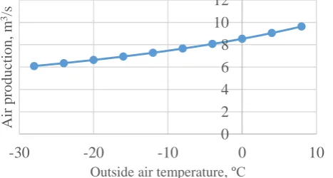
Figure 12 shows the dependence of the heat generator performance on the outside air temperature at a fuel consumption rate of 0.01 kg/s. As seen from this figure, a decrease in the outside air temperature leads to a decrease in productivity. In Kazakhstan, the heating season starts from the temperature of 8°C, therefore the calculation was carried out from 8°C to -28°C, in increments of 4°C. With a constant fuel consumption rate of 0.01 kg/s, depending on the outside air temperature, performance can vary in the range of 6-10 m3/s.
Fig. 12. Dependence of the heat generator performance on the outside temperature at a constant fuel consumption rate
IV. CONCLUSIONS
Based on the experiment and numerical simulation, the authors made the following conclusions:
1) The process of flame stabilization is significantly affected by the location of perforations on V-gutter flameholders;
2) Fuel supply from the bottom side of the V-gutter along the symmetry axis results in a slight increase in the emission of nitrogen oxides. It also leads to an increase in combustion efficiency and the exhaust gas temperature. It is particularly important for designing heat generators for autonomous heating of office buildings, such as universities;
3) The photos presented by the authors confirm the data obtained by measurements. It can also be seen that the flame itself significantly affects the way of fuel supply. For example, when the fuel is supplied from the bottom side of the V-gutter, the horizontal position of the flame is changed into the upper side;
4) The numerical simulation of the combustion process behind semi-perforated V-gutter flameholders has confirmed the research findings. It also helped to reveal the influence of the equivalence ratio φ on the process of flame forming;
5) The heat-generating setup circuit presented on the basis of microflame devices in the form of semi-perforated V-gutter flameholders may be used as a source of heating of buildings with air heating. The modified setup circuit may also be used in the hot water supply system of buildings, such as universities;
6) Based on the experiment, numerical simulation and mathematical calculation, the authors presented the formula of dependence of the heat generator performance on fuel consumption;
7) The calculation of the heating setup indicates high performance in any period of the heating season.
Based on these findings, the authors recommend the use of heat generators on the basis of semi-perforated V-gutter flameholders as a source for autonomous building heating. V-gutter flameholders can also be applied in gas turbine combustors. They make it possible to: 1. increase the combustion intensity; 2. improve the environmental performance as well as significantly reduce the formation of nitrogen oxides, 3. reduce the size and metal intensity of equipment, thereby increasing the reliability and reducing the complexity of operation.
V. NOMENCLATURE
Cpg – heat capacity of gas at constant pressure [kJkg-1K-1] Cpa - heat capacity of air at constant pressure [kJkg-1K-1] d – nozzle diameter [mm]
Lfh – length of flameholder [mm]
L0 – stoichiometric coefficient (=10·10-3·0,266·Qwl)[-] Qwl – lower heating value of fuel [kJm-3]
T0 – outside temperature [K]
Tg – gas temperature at the output [K] Wg – gas speed [m/s]
Wa – air speed [m/s] Greek symbols ρg - gas density [kgm
-3 ] ρa – air density [kgm-3] φ – equivalence ratio [-]
φout – equivalence ratio at the output
REFERENCES
[1] J.R. Dawson, R. L. Gordon, J. Kariuki, E. Mastorakos, A. R. Masri, M. Juddoo, Visualization of blow-off events in bluff-body stabilized turbulent premixed flames. Proceedings of the Combustion Institute 33, 2011, pp. 1559–1566.
[2] A. M. Mellor, Prog. Energy Combust. Sci. 6, 1980, 347–358. [3] A. H. Lefebvre, Gas Turbine Combustion. Taylor and Francis,
1998.
[4] S. J. Shanbhogue, S. Husain, T. Lieuwen, Prog. Energy Combust. Sci., 35, 2009, 98–120.
[5] P. Kumar, D. P. Mishra, Effect of bluff-body shape on LPG-H2 jet diffusion flame, International journal of hydrogen energy, 33, 2008, 2578-2585.
[6] G. Newbold, J. R. Nathan, G. J. Nobes, S. R. Turns, Measurements and predictions of NOx emissions from unconfined propane flames turbulent-jet, bluff-body, swirl, and processing jet burners. In: Proceedings of 28th international symposium on combustion, 2000, pp. 481-487.
0 10 20 30 40 50 60 70 80
0 0.02 0.04 0.06
A
ir
ca
p
ac
ity
,
m
3/s
Fuel consumption, kg/s
0
2
4
6
8
10
12
-30
-20
-10
0
10
A
ir
pr
oduct
ion
,
m
3/s
[7] S. H. Kim, K. Y. Huh, Use of the conditional moment closure model to predict NO formation in a turbulent CH/JH2 flame over
a bluff-body. Combust Flame, 130, 2002, 94-111.
[8] V. A. Khristich, V. N. Litoshenko, Investigation of the counter flow zone dimensions behind the system of corner flameholders. Herald of KPI. Thermal engineering series, 5, 1968, pp.10-15 (in Russian).
[9] L. S. Butovskiy, V. A. Khristich, The structure of mixing zone and particular qualities of burning behind triangle flameholder, in: Theory and practice of gas burning, Leningrad, 1972, pp. 76-82 (in Russian).
[10] V. A. Khristich, G. N. Lyubchik, About the stability of diffusional combustion behind flameholders, in:Theory and practice of gas burning, Leningrad, 1972, pp. 82-85 (in Russian). [11] V. A. Khristich, G. N. Lyubchik, The influence of gas fuel type of combustion process of jet-stabilizer burners, in: Theory and practice of gas burning, Leningrad, 1972, pp. 12-132 (in Russian).
[12] V. A. Khristich, A. G. Tumanovskiy, Gas turbine engines and environmental protection. Kiev, Technics, 1983, 144 p. (in Russian).
[13] Aiwu Fan, Jianlong Wan, Yi Liu, Boming Pi, Hong Yao, Wei Liu, Effect of bluff body shape on the blow-off limit of hydrogen/air flame in a planar micro-combustor. Applied Thermal Engineering, 62, 2014, 13-19.
[14] Aiwu Fan, Jianlong Wan, Kaoru Maruta, Hong Yao, Wei Liu, Interactions between heat transfer, flow field and flame stabilization in a micro-combustor with a bluff body.
International Journal of Heat and Mass Transfer, 66, 2013, 72– 79.
[15] Jianlong Wan, Aiwu Fan, Kaoru Maruta, Hong Yao, Wei Liu, Experimental and numerical investigation on combustion characteristics of premixed hydrogen/air flame in a micro-combustor with a bluff body. International Journal of Hydrogen Energy, 37, 2012, 1 9 1 9 0-1 9 1 9 7.
[16] Aiwu Fan, et al., The effect of the blockage ratio on the blow-off limit of a hydrogen/air flame in a planar micro-combustor with a bluff body, Int. J. Hydrogen Energy, 38, 2013, 11438-11445. [17] Bok Jik Lee, Chun Sang Yoo, Hong G. Im, Dynamics of
bluff-body-stabilized premixed hydrogen/air flames in a narrow channel. Combustion and Flame, 162, 2015, 2602–2609. [18] K. S. Kedia, A. F. Ghoniem, The anchoring mechanism of a
bluff-body stabilized laminar premixed flame. Combustion and Flame, 161, 2014, 2327–2339.
[19] P. A. Khavanov, Autonomous heat supply system - an alternative or a step back? Ventilation, Heating, Air-Conditioning, Heat Supply and Building Thermal Physics (ABOK). 2004, 1, pp. 34-37.
[20] D. G. Usadskiy, Improvement of autonomous heat sources circuits in the heating and hot water supply systems. Dissertation thesis. Volgograd, 2011, 197 p.
[21] Autonomous heating [Textbook]. V. M. Polonskiy. Moscow: ASV, 2007, 152 p.
[22] ANSYS FLUENT 13.0 Theory Guide. [23] ANSYS FLUENT 13.0 User’s Guide.
[24] O. P. Bannykh, Basic designs and thermal analysis of heat exchangers [Textbook]. Saint Petersburg: SPbNIU ITMO, 2012, 42 p.
Dias Raybekovich Umyshev
Date of birth: 31.01.1990. He is a Master of Science of the Department of Thermal power plants at Almaty University of Power Engineering & Telecommunications.
His main research interests are engineering, mechanics of liquids and gases, energy. Latest publications were in local journals (Kazakhstan).
Issakhan Amantaevich Zholbaryssov
Date of birth: 02.01.1990. He is a Master of Engineering Science of the Department of Thermal power plants at Almaty University of Power Engineering & Telecommunications.
His main research interests are energy, energy saving and energy efficiency. Latest publications were in local journals (Kazakhstan).
Nina Gavrilovna Borissova
Date of birth: 19.06.1952. She is a Candidate of Physical and Mathematical Sciences, Associate Professor of the Department of Thermal
power plants at Almaty University of Power Engineering & Telecommunications.
Her main research interests are energy, energy audits, energy conservation and efficiency. Latest publications were in local journals (Kazakhstan).
Abay Muhamediyarovich Dostiyarov
Date of birth: 21.08.1951. He is a Doctor of Technical Sciences, Professor of the Department of Thermal Engineering at Kazakh Agrotechnical university named after S.Seifullin.
His main research interests are engineering, mechanics of liquids and gases, energy. Latest publications were in local journals (Kazakhstan).
Nassipkul Kasszhanovna Dyussembekova
Date of birth: 23.06.1977. He is a PhD, Associate Professor of the Faculty of Engineering and Economic Sciences at German-Kazakh University.
Her main research interests are energy, environment. Latest publications were in local journals (Kazakhstan).
Olga Aleksandrovna Stepanova
Date of birth: 30.08.1966. She is a Candidate of Technical Sciences, Associate Professor of the Department of Technical Physics and combined heat and power at State University named after Shakarim.
Her main research interests are energy, boilers, combustion processes. Latest publications were in local journals (Kazakhstan).
Musakul Elekenovich Tumanov
He is a Candidate of Technical Sciences, Professor, Associate Proffesor of the Department of Thermal power plants at Almaty University of Power Engineering & Telecommunications.