JETIRJ006027 Journal of Emerging Technologies and Innovative Research (JETIR) www.jetir.org 168
Implementation of synchronized space vector PWM
for a Two-level Inverter using the digital I/O pins of
the dSPACE hardware platform
1 Srinvas Reddy Chalamalla, 2 P Parthasaradhi Reddy 1 Assistant Professor, 2 Associate Professor 1 Department of Electrical and Electronics Engineering 1 Guru Nanak Institutions Technical Campus, Hyderabad, India
Abstract : This paper presents soft starting and speed control a 3-phase induction motor is obtained by (v/f) control. A voltage source inverter (VSI) is employed to impress a variable voltage, variable frequency supply to the motor. The VSI is controlled by dSPACE (an acronym digital signal processing and control engineering), hardware platform, which supports a hardware-in-loop feature. Simulink models can be converted into assembly language programs of the target DSP platform and can be downloaded into the target platform to run various real time applications. Six dedicated PWM lines are provided in dSPACE. Thus, two independent inverters can be simultaneously controlled. However these PWM lines can implement only asynchronous PWM not possible to ensure as it is an integral ratio of the carrier wave and modulating wave under all conditions. Consequently, it calls for the exploration of the capabilities of some other resources available with the dSPACE platform. It was found that one may configure the digital I/O lines provided by the dSPACE as PWM lines if the switching frequency is not high. In this paper the general purpose digital I/O lines are programmed as PWM lines to drive the VSI, which employs synchronous space vector modulation.
IndexTerms - dSPACE, soft starting, voltage source inverter (VSI), PWM, synchronous space vector modulation.
I.INTRODUCTION
An electric motor is a machine which converts electrical energy into mechanical energy. Its action is based on the principle that when a current carrying conductor is placed in a magnetic field, it experiences a mechanical force whose direction is given by Fleming’s left hand rule. In D.C motors the electric power is conducted directly to the armature through brushes and commutator. But in Induction motors, the rotor does not receive power by conduction but by induction. That is three phase supply is given to the stator of the induction motor, this power is transferred to rotor by induction principle. Balanced polyphase currents in polyphase windings produce constant amplitude rotating mmf wave.
The stator produced mmf wave and rotor produced mmf wave both rotate in the air gap in the same direction at synchronous speed. These two mmf waves are thus stationary with respect to each other, consequently the development of steady state torque is possible. The stator and rotor mmf waves combines to give the resultant air gap flux wave of constant amplitude and rotating at synchronous speed.
Although it has been superseded open loop Volt/Hertz control or Scalar Control as it is known, is still widely used in applications where don’t require precise speed control such as fans for Heating Ventilation and Air Condition (HVAC). This method is based on the torque speed curve for an induction motor. The shape of this curve depends on the voltage and frequency applied to the stator. By fixing the supply frequency and hence the motor speed, the torque can be varied as the square of the applied voltage. To maintain the air gap flux at its rated value the voltage and frequency should be varied in the same proportion i.e. if you double the frequency you need to double the supply voltage.
Providing the ratio between voltage and frequency remains constant maximum torque can be applied throughout the motors speed range. At low frequencies the supply voltage is also low so the voltage drop caused by the stator resistance cannot be neglected. To compensate for this the voltage below a certain frequency is maintained at a fixed value and the V/Hz relationship is abandoned. Similarly at high frequencies the voltage is fixed at a maximum value to avoid insulation breakdown.
JETIRJ006027 Journal of Emerging Technologies and Innovative Research (JETIR) www.jetir.org 169 II.PROBLEM FORMULATION
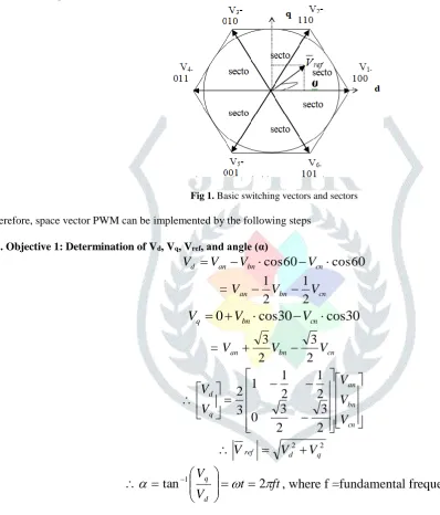
The eight vectors are called the basic space vectors and are denoted by V0(000), V1(100), V2(110), V3(010), V4(011), V5(001), V6(101), V7(111). The binary numbers indicate the switch state of inverter legs. Here 1 implies upper switch being on and 0 refers to the lower switch of the leg being on. The same transformation can be applied to the desired output voltage to get the desired reference voltage vector Vref in the d-q plane. The objective of SVPWM technique is to approximate the reference voltage vector Vref using the eight switching patterns.
One simple method of approximation is to generate the average output of the inverter in a small period, T to be the same as that of Vref in the same period.
Fig 1. Basic switching vectors and sectors Therefore, space vector PWM can be implemented by the following steps
2.1. Objective 1: Determination of Vd, Vq, Vref, and angle (α)
60
cos
60
cos
an bn cnd
V
V
V
V
=
V
anV
bnV
cn2
1
2
1
30
cos
30
cos
0
bn cnq
V
V
V
=
V
anV
bnV
cn2
3
2
3
cn bn an q dV
V
V
V
V
2
3
2
3
0
2
1
2
1
1
3
2
2 2 q d refV
V
V
t
ft
V
V
d
q
tan
1
2
, where f =fundamental frequency.
2.2. Objective 2: Determination of time duration T1, T2, T0 Switching time duration can be calculated as follows:
Switching time duration at Sector 1
1 1 21 1 2
0
0 2
1
0
T T T
T T T T T ref z z
V
dt
V
dt
V
V
)
.
.
(
T
1V
1T
2V
2V
T
z
ref
3
sin
3
cos
3
2
0
1
.
3
2
sin
cos
2 1
dc dc refz
V
T
V
T
V
JETIRJ006027 Journal of Emerging Technologies and Innovative Research (JETIR) www.jetir.org 170
(where, 0 ≤ α ≤ 60°)
dc ref
z z z
V
V
a
and
f
T
where
T
T
T
T
3
2
1
2 1 0
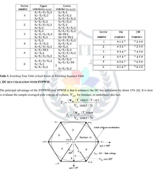
2.3. Objective 3: Determination of the switching time of each switch (S1 to S6)
Table 1. Switching Time Table at Each Sector & Switching Sequence Table III.DC BUS UTILIZATION WITH SVPWM
The principal advantage of the SVPWM over SPWM is that it enhances the DC bus utilization by about 15% [6]. It is instructive
to evaluate the sample-averaged pole voltage of a phase,
V
AO forinstance, to understand this fact.)
3
/
sin(
)
3
/
sin(
|
|
1
dc s
V
T
T
v
sr
)
3
/
sin(
sin
|
|
2
dc s
V
T
T
v
srFig 2. Determination of the sample-averaged pole voltage Which are calculated already.
JETIRJ006027 Journal of Emerging Technologies and Innovative Research (JETIR) www.jetir.org 171 IV.RESULTS AND DISCUSSION
Soft starting minimizes the starting mechanical and thermal stress and shocks on the machine and the motor. It results in reduced maintenance cost, fewer breakdowns and hence longer operating life for both. Reduced starting current is an added advantage. A solid-state soft start is that an unbalanced power supply is transformed to a balanced source of supply automatically by suitably adjusting the firing angle of each SCR or IGBTs through their switching logistics.
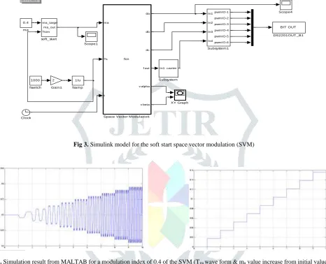
Fig 3. Simulink model for the soft start space vector modulation (SVM)
Fig 4. Simulation result from MALTAB for a modulation index of 0.4 of the SVM (Tga wave form & ma value increase from initial value to its
final value)
Fig 5. Experimental results with dSPACE control circuit for modulation index of 0.4 output voltage and current of the SVM
ma_target Tsim
ma_out
soft_start 0.4
ma
1000 fswi tch
1/u fsamp
XY Graph
In1 In2 In3 In4
pwmIO-1 pwmIO-2 pwmIO-3 pwmIO-4 pwmIO-5 pwmIO-6
Subsystem1
In1 carrier
Subsystem
ma
Ts
t
da
db
dc
f out
v alpha
v beta
fcn
Space Vector Modul ati on
Scope4
Scope1 RT I Data
2 Gai n1
BIT OUT DS2201OUT _B1
JETIRJ006027 Journal of Emerging Technologies and Innovative Research (JETIR) www.jetir.org 172 V. CONCLUSIONS
A voltage source inverter (VSI) is employed to impress a variable voltage, variable frequency supply to the motor. The VSI is controlled by dSPACE (an acronym digital signal processing and control engineering), hardware platform, which supports a hardware-in-loop feature. Six dedicated PWM lines are provided in dSPACE. Thus, two independent inverters can be simultaneously controlled. In this paper the general purpose digital I/O lines are programmed as PWM lines to drive the VSI, which employs synchronous space vector modulation. Consequently, it calls for the exploration of the capabilities of some other resources available with the dSPACE platform. It was found that one may configure the digital I/O lines provided by the dSPACE as PWM lines if the switching frequency is not high.
VI. ACKNOWLEDGEMENT
This research work is based on the support of Guru Nanak Institutions Technical Campus 2018.
REFERENCES
[1] A.K. Gupta; A.M. Khambadkone ; K.M. Tan: A two-level inverter based SVPWM algorithm for a multilevel inverter. 30th Annual Conference of IEEE Industrial Electronics Society, 2004. IECON 2004. 0-7803-8730-9.
[2] Srinivas Reddy Chalamalla, S. Tara Kalyani: Analysis of IM Fed by Multi-Carrier SPWM and Low Switching Frequency Mixed CMLI. International Journal of Advanced Research in Electrical, Electronics and Instrumentation Engineering, 2013. ISSN ONLINE(2278-8875).
[3] Atif Iqbal, Adoum Lamine, Imtiaz Ashraf, Mohibullah: Matlab/Simulink Model of Space Vector PWM for Three-Phase Voltage Source Inverter. International Universities Power Engineering Conference. 978-186135-342-9.
[4] G.D. Holmes, T.A. Lipo: Pulse Width Modulation for Power Converters - Principles and Practice. IEEE Press Series on Power Eng., Piscataway, NJ, USA: John Wiley and Sons, 2003.
[5] M. Depenbrock: Pulsewidth control of a 3-phase inverter with nonsinusoidal phase voltages. In Proc. IEEE-IAS Int. Semiconductor Power Conversion Conf., Orlando, FL, 1975, pp. 389-398.
[6]Emil Levi, Drazen Dujic, Martin Jones: Analytical Determination of DC-Bus Utilization Limits in Multiphase VSI Supplied AC Drives. IEEE Transactions on Energy Conversion Volume: 23, Issue: 2, June 2008 1558-0059.
[7] [Online] https://www.dspace.com/en/inc/home/products/hw/simulator_hardware/scalexio/scalexio_ds6201.cfm
[8] [Online] https://www.dspace.com/en/inc/home/products/sw/impsw/realtimeinterf.cfm