Feasibility Studies on Use of Water Mist For Plume Infrared
Suppression
Amit Tyagi
1, P M V Subbarao
21 Centre for Fire, Explosive& Environment Safety (CFEES), Defence R & D Organisation (DRDO), Timarpur,Delhi-110054, INDIA
2 Professor, Mechanical Engineering Department, Indian Institute of Technology (IIT), HauzKhas, New Delhi-110016, INDIA
Abstract:In present study, for the suppression of infrared signature of hot exhaust plumes, the experimental and numerical studies are performed. The IR suppressant considered in the present study is water mist. The objective of the present study is to explore and assess the efficacy of poly-disperse water mist for infrared signature suppression applications. For this purpose, a series of experiment is conducted on a lab scale experimental facility. The computational modeling and simulation work is carried out using Ansys Fluent v12.0 commercial code. The optimization of water mist parameters like droplet size, injection velocity, injection configuration and type of atomizer etc. with respect to infrared signature attenuation is included in the study. The radiation attenuation of upto67% is obtained using water mist injection. That means the water mist has remarkable ability to shelter the infrared radiation from the hot exhaust plume. This study suggests the use of appropriate poly-disperse water mist for IR suppression applications.
Keywords: atomizer, infrared, plume, poly-disperse, water mist.
Nomeclature
CFD Computational Fluid Dynamics IR Infra-Red
IRSS Infrared Signature Suppression DPM Discrete Phase Model
SMD Sauter Mean Diameter ƐCO2 Emissivity of CO2 ƐH2O Emissivity of H2O Eg Emissive power (W/m2) We Weber number
ρ Density
l Characteristic dimension V Relative velocity of droplet Σ Surface tension
I.
INTRODUCTION
The major source of Infrared signature on any mobile or immobile platform is its engine producing high temperature exhaust gaseous products. TheIR emission from these hot plumes and their subsequent identification may lead to catastrophe in defence scenario.The exhaust products mainly comprises ofCO2, CO, H2O(v) and N2.The diatomic molecules with zero dipole moment like CO and N2 doesn’t participate in IR emission. Thus, the main IR contributor gases are CO2 and H2O(v). The plume IR signature is dependent upon the temperature and concentrations of these contributor gases, which needs to be suppressed for enhancing the platform survivability.Thus, the problem reduces down to the cooling of hot exhaust gaseous plume by some means. The current methods used for plume cooling mainly employ air dilutioncooling arrangements [4][5][7][8][11][12][13][14][22][27][28][29[30]. But, due to stringent survivability requirements, better cooling arrangements and devices are always in high demand.
Different platforms may have different cooling needs and thus, water mist parameters needs to be selected appropriately. In present work, the parametric study w.r.t.droplet size, injection velocity, angle of injection, atomizer type and atomizer configuration is carried out for a lab scale facility. Experimental work is performed on a lab scale model test facility. The computational study is performed using commercial code Ansys Fluent v12.0. DPM model is used to simulate the interaction between plume and water mist droplets. Model validation with the experimental data is also included in this study.
II.
LITERATURE REVIEW
The water mist technology has originally been explored as halon alternative for fire suppression applications due to the implication of Montreal protocol [6]. Meanwhile, a number of other significant applications emerged out for water mist technology including that of IRS systems [11]. The traditional IRS systems are based on the cooling of exhaust plume using air ingress concept to reduce the effective plume temperatures upto 250oC [2][7][8].
A.M. Birk and D. Vandam [12] carried out sea trials on a 1/4th scale model for an IR suppression system. The results showed that full scale system performance was better due to Reynolds number effects. Mahulikar et al. [5][13] highlights the infrared signature suppressor device for aerospace vehicles. The signatures of aerospace vehicles are shown to be managed by incorporating the changes in diffusor outlet section.
It is reported by the researchers S.F.Wang et al. [28] that the constant area mixing occurs very slowly in an ejector. Conventional ejectors need mixing duct lengths greater than ten to generate near uniform flow. For this reason, the use of forced mixer lobes in ejectors has been researched quite extensively over the last fifteen years
Yong et al. [14] suggested the mixing enhancement in plume flow using a lobed forced mixer shape. This study clearly indicates that turbulence causes more mixing resulting into the better water evaporation rates [2].
Barik et al. [8][30] studied the effect of using circular and non-circular multiple nozzles and louvred funnel on the air entrainment. The effect of diffuser ring overlap height is studied and discussed in detail. The researcher Barik et al. [29] have also carried out the experimental and numerical analysis of the air entrainment into IRS device i.e. ejector-diffuser system.
The interaction of water droplets with the EM waves is also discussed in various papers. The droplets participate in Mie scattering, Rayleigh scattering [1][15] or non-selective scattering depending upon their sizes and incident wavelengths.
Simo Hostikka et al. [16] presented that water droplets attenuate radiation by absorption and scattering. The process of droplet evaporation is highly dynamic in the sense that its size decreases during evaporation [17].
The early work of Sjenitzer and Ingebo [2] shall be much appreciated related to the droplet evaporation injected into hot stream which provided the basis for evaporation modelling correlations to many software codes. But, their work didn’t take the droplet breakup and coalescence into consideration. Droplet breakup and coalescence models discussed in few studies are relevant only in case of high stream flows. The droplet breakup models consider the criteria based on critical weber number [15][18]. The Weber number (We) is a dimensionless number in fluid mechanics which is useful in analysing the fluid flows where there is an interface between two different fluids, especially for multiphase flows with strongly curved surfaces.
………..(1)
Godoy et al. [19] developed the analytical expressions to scale the extinction, scattering and absorption coefficients as a function of the SMD for poly-disperse water sprays.
Nirukumari et al. [20] analysed the evaporating mist flow for enhanced convective heat transfer. This study highlights that the latent heat of evaporation of water has to be better exploited for getting maximum benefit.
Ting Wang and J. Leo Gaddis [21] conducted experiments to study the cooling effect of water mist in a heated horizontal tube. The mist/steam mixture was obtained by blending fine water droplets (3 to 15 mm in diameter) with the saturated steam at 1.5 bar. Two mist generation systems were tested by using the pressure
2
.V .l W e
III.
EXPERIMENTAL STUDY
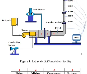
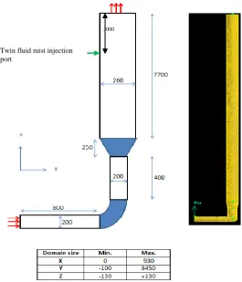
A lab scalemodel test facility is used to assess the efficacy of water mist for IR signature suppression applications as shown in figure-1.The exhaust duct has dimensions about one-eighth meter diameter and 3 m height. This exhaust facility comprises of a pressure fed burner, a combustion blower, a twin lobe root blower, a combustion chamber, a mixing chamber, a horizontal duct and a vertical duct section.
Figure 1: Lab scale IRSS model test facility
The exhaust facility generates hot gases by burning LDO fuel at a rate of30 lph.The exhaust gas flow rate of the order 0.8-1.1 kg/s is achievable at plume temperature around550-600Kand exhaust composition as 4% CO2, 2% H2O(v) and 94% N2 (by volume). The plume flow rate and temperature are controllable by a VFD (variable frequency drive) attached to a root blower control. A total of five temperature sensors are positioned along the height of the exhaust duct for measuringplume temperature. An atomizer section is fitted onto the exhaust duct for fitting of water mist atomizers. The measured temperature is communicated to the 20 channel data acquisition system and stored on an inter-connected PC for further post-processing.
The rate ofmist injectionis decided on the basis of enthalpy balance between hot plume and water mist which comes out to be around 6 lpm. The droplet size is selected on the basis of single droplet evaporation model[6]. Using above data, appropriate selection of atwin-fluid water mist atomizer is done.
The selected atomizer operates at 2-3 bar water pressure and 4-6 bar air pressure with flow rate of 1.5-2.0 lpm. The pressurized water and air are fed into the twin-fluid atomizer for water mist generation. The twin fluid atomizer is shown in figure-2.
Figure 2: Twin fluid water mist atomizer
1 2 3 4
Firing chamber
Mixing chamber
Convergent section
Exhaust duct
TWO PHASE INTERNALLY MIXED ATOMIZER
8 orifice, Ø2mm Mist outlet
Inner chamber
Water inlet Ø15mm ID
Air inlet Ø15mm ID
Ø3mm water discharge ports
6 orifice, Ø2mm air inlet port O- ring Ø32mm O- ring Ø21mm Qw 2 lpm, Pw 2 bar
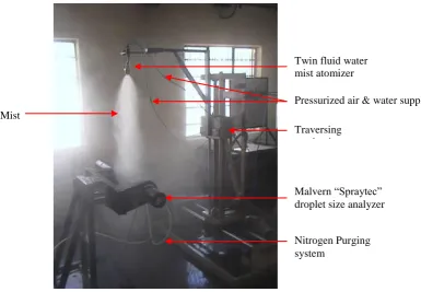
The atomizer characterization is performed using in-house characterization facility comprising of Malvern’s “Spraytec” droplet size analyzer instrument. The droplet size is observed in the range of 30-50 µm. The characterization setup is shown in figure-3.
Figure 3: Atomizer characterization facility
The droplet size distribution shows that SMD size parameter is of the order of 23 µm when atomizer is characterized at 200mm distance below its exit as seen in figure-4. SMD is universally acclaimed as a mean spray diameter for applications where active surface area is of prime concern like droplet evaporation and phase change applications, as in present case.
Figure 4: Droplet size distribution @ 4 bar air pressure and 2 bar water pressure at 200mm from atomizer.
This data will also be fed to the computational model.A series of experiment is performed with and without water mist injection into the exhaust plume. The comparison of water mist cooling w.r.t. dilution air cooling is presented in figure-5 experimental result.
Traversing mechanism Twin fluid water mist atomizer
Malvern “Spraytec” droplet size analyzer
Nitrogen Purging system
Mist
Figure 5: Temperature-time curve (air vs. mist cooling)
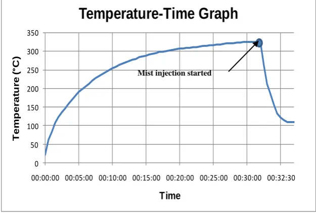
From figure-5, it is clear that air cooling arrangements are ineffective in comparison to their mist cooling counterpart system. With mist cooling, a temperature reduction of the order 200-220oC may be achieved. Few experiments were conducted to optimize the mist injection rate. Fig.-6 & 7 below presents the corresponding experimental curves.
Figure 6: Tempertaure-time curvefor two atomizers case (total mist injection=3 lpm)
Figure-6 shows that plume temperature reduces by 220oC almost instantaneously during mist injection using two atomizers fitted opposite to each other.The experimental data has been obtained for various mist injection rate, atomizers location and theirconfiguration.
0 50 100 150 200 250 300 350
00:00:00 00:05:00 00:10:00 00:15:00 00:20:00 00:25:00 00:30:00 00:32:30
T
e
m
p
e
ra
tu
re
(
°
C)
Time
Temperature-Time Graph
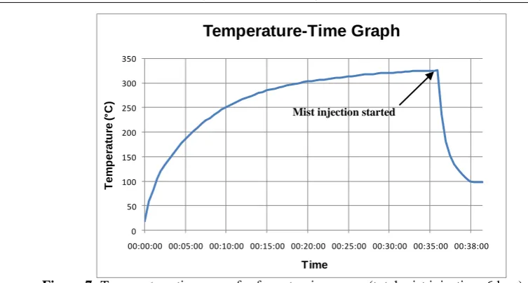
Figure 7: Temperature-time curvefor four atomizers case (total mist injection=6 lpm)
Figure-7 shows that plume temperature reduction of 230oC when using four water mist atomizers. From figure-6&7, it is clear that there is no appreciable reduction in average plume temperature by injection of water mist beyond an optimal quantity. Each additional atomizer module may result in significant increase of overall system cost, complexity and maintenance at the advantage of slight reduction in plume temperature.Thus, the optimization of mist parameters is of utmost importance for designing of efficient plume cooling systems.It is cumbersome and highly demanding in terms of resources to conduct the parametric optimization using experiments. Thus, a CFD model isdeveloped using Ansys Fluent v12.0 software package to aid the experimental study. The next section covers the computational efforts.
IV.
COMPUTATIONAL STUDY
A 3D computational domain is created using Gambit pre-processor. Grid parametric study is carried out to arrive at a final optimum mesh size. The axi-symmetric model cannot be used because of asymmetric flow physics. Thus, full 3D model needs to be simulated. The exhaust plume containing a mixture of three gases namely, H2O, CO2 and N2 is modelled using species transport model. The average material properties are calculated using rule of mixture. Boundary conditions for gas flow are taken as mass flow inlet and pressure outlet. Standard k-Ɛ turbulence model is selected after evaluating the effect of various turbulence models on the final solution. No appreciable changes are observed in the solution by selecting other than std. k-Ɛ model.
4.1 Geometry and mesh
The computational geometry consists of a cylindrical duct with external insulated wall, a duct interior, an inlet and outlet boundary. The computational domain is shown in figure-8. The numerical simulations are performed on a three-dimensional domainfilled withtetrahedral computational volumes. A grid independence study suggested a final grid consisting of approximately 5, 37,000 cells.
0 50 100 150 200 250 300 350
00:00:00 00:05:00 00:10:00 00:15:00 00:20:00 00:25:00 00:30:00 00:35:00 00:38:00
T
e
m
p
e
ra
tu
re
(
°
C)
Time
Temperature-Time Graph
Figure 8: Computational domain of model test facility
4.2 Boundary Conditions (B.C.)
The boundary conditions are defined for both phasesi.e. gaseous plume and water droplets. Gas phase B.C.:
Inlet
“Mass flow inlet” with mdot=1.1 kg/s; T=600 K; mixture of CO2, H2O(v) and N2simulated using species transport model, std. k-e turbulence model, turbulent intensity-5%.
Outlet
“Pressure Outlet” at STP conditions.
Duct cylindrical wall
Default-Insulated, no-slip wall. Droplet B.C.
“trap” at inlet, “escape” at outlet and “rebound” at duct interior wall. Water mist injector model
Solid cone spray, droplet size-30 to 50 µm, injection velocity- 50 to 100 m/s, direction of injection- towards the duct center, mono-disperse SMD size distribution.
4.3 Assumptions
The following assumptions are made to accommodate the modelinglimitations &challenges: The gas phase is compressible and the mixture satisfies the equation of state for ideal gas. Fluid properties are independent of temperature.
Plume inlet velocity profile is assumed constant. Droplets remain spherical throughout.
Droplets are considered point sources of mass, momentum and energy. Each droplet parcel represents single droplet behavior.
Dynamic drag law isnot applied.
Superheating of water vapors is neglected. Two-way turbulence coupling is incorporated. Single fluid atomizers are used.
Twin fluid mist injection port
4.4 Computational model
The CFD model is developed using the Discrete Phase Model (DPM) of Ansys Fluent v12.0 software package. Droplets interact with the hot gas plume in a number of ways i.e. further breakup or coalescing either with each other or with the liquid film on the inner wall of the duct. But the droplet-droplet interaction or four-way coupling is neglected. Only two-four-way coupling is included in the present model i.e. effect of water mist injection causing the turbulence in the continuous gas phase and vice-versa is considered.SMD size distribution is assumed applicable to the present study as proved in various literature studies [31]. P-1 radiation and droplet interaction model is considered.
As soon as the droplets come in contact with the hot gaseous plume, evaporation starts. The evaporation rate of water mist depends upon the droplet size, gas plume speed, ambient pressure, temperature and humidity level inside the duct. The volume of gas phase, and consequently the linear velocity of the gas, changes as a result of two opposing effects i.e. decrease of temperature and increase of matter (due to mist evaporation).
A mist injection rate of 6 lpm means injection of approximately 1010 number of discrete 50 µm mono-disperse droplets per minute into the flow domain. The solution of the individual droplet equations will lead to cumbersome and unpractical computational approach. To handle the computational complexity, DPM module uses the concept of parcels assuming the droplet clusters having uniform behavior for entire droplet set contained within a single parcel. Such parcels can be dealt with reduced computational efforts.
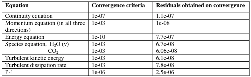
The mass, momentum and energy exchange takes place between the two phases. The simulations are steady in nature. Firstly, gas flow is independently solved, and after obtaining gas solution convergence, the DPM model or atomizer model is activated and solved along with the gas phase simultaneously to get the overall stabilized solution residuals. The residuals are set to the low value of 1e-03 to 1e-10 so that the solution gets enough time to converge. The under-relaxation factors are initially set to the value of 0.7-0.9 to avoid solution divergence.At first, only gas phase flow field is solved. After the gas flow solution convergence, discrete phase i.e. water droplets are solved to get simultaneous convergence of the flow field. Running the solution for around 12500 number of iteration, the residuals looks stable and solution convergence is reported. The convergence criteria for the residuals of various equations and the residuals achieved on solution convergence are tabulated in Table-1.
Table 1: Convergence criteria and residuals obtained on convergence
The computational results are presented in the next section.
4.5 Results& Discussion
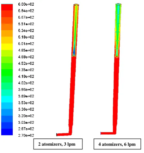
Two simulation cases are solved in this study, firstwith two water mist atomizers and another with fouratomizers. The results are presented height wise on ductmid-plane as shown in figure-9 & 10.
Equation Convergence criteria Residuals obtained on convergence
Continuity equation 1e-07 1.1e-07
Momentum equation (in all three directions)
1e-03 1e-08
Energy equation 1e-10 7.7e-07
Species equation, H2O (v) CO2
1e-03 1e-03
6.7e-08 6.06e-08
Turbulent kinetic energy 1e-03 6.1e-08
Turbulent dissipation rate 1e-03 7.8e-08
Figure 9: Temperature (K) profile at different y-planes (5, 5.45,5.95, 6.45,6.95,7.45,7.95,8.45m from inlet)
Figure 10: Temperature (in K) profile at z=0 plane
It is evident from figure-10 that the mist flow rate of 6 lpm is able to reduce down the plume temperature from 600K to nearly 400K in case of twin fluid atomizer system. The atomizers are placed at 90Oapart circumferentially injecting towards the duct center. In case of 2 atomizer simulation, no appreciable temperature
@ OUTLET; Avg. T=404 K
Y=7950mm; Avg. T= 410 K
Y=7450mm; Avg. T= 419 K
Y=6950mm; Avg. T= 431 K
Y=6450mm; Avg. T= 446 K
Y=5950mm; Avg. T= 466 K
Y=5450mm; Avg. T= 576 K
Y=5000mm; Avg. T= 599 K
2 atomizers, 3 lpm 4 atomizers, 6 lpm
523 K
523 K
523 K
523 K
524 K
525 K
589 K
599 K
reduction is seen beyond y=6450mm. Thus, only the 4-atomizer twin fluid case results will be presented in this section from now onwards.
Figure 11: Contours of H2O (v) mole fraction at z=0 plane and y-planes (y=5, 5.45, 5.95, 6.45, 6.95, 7.45,
7.95, 8.45m from inlet)
The mass weighted average value of mass fraction of H2O (v) at duct outlet section is 0.135. The fraction is increasing moving from point of mist injection (y=5450mm) towards duct outlet (y=8450mm) due to evaporation of water droplets as seen in figure-11.
Mass wt. avg. =0.135
Z=0 plane Y- planes
The mass weighted average value of mass fraction of CO2 at duct outlet section is 0.0227. The fraction is decreasing moving from point of mist injection (y=5450mm) towards duct outlet (y=8450mm) due to evaporation of water droplets as seen in figure-12.
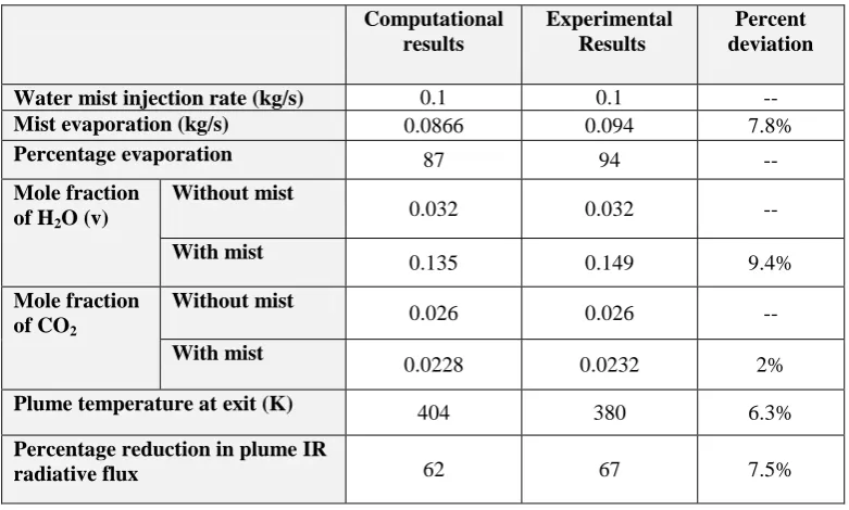
The comparison of the computational results with the experimental results is given in Table-2 and shows that the reduction in plume IR emission takes place by the cumulative effect of decrease in plume temperature and increase in plume emissivity.
The computational results matches reasonably well with the experimental results showing an overall discrepancy of not more than 10%.
V.
CONCLUSIONS
The preliminary results discussed here suggest that a mist based plume cooling systemis highly efficient in suppressing the IR signal strength. The most important thing is to arrive at the appropriate mist parameters. Turbulence created due to mist momentum and flux density results into the dynamic mixing of hot plume and water droplets leading to greater mist evaporation rates and IR reduction as well. The swirl type atomizers may also be tried to enhance the turbulence to another higher levels. Design of such systems requires enormous computational efforts in addition to the limited experimental study for collecting data for model validation.Themodel validation is achieved by comparison with the experimental values within a discrepancy of 9-10%.
VI.
ACKNOWLEDGEMENT
The experimental test facility is installed and commissioned at CFEES, DRDO, Delhi, India. I acknowledge my heartiest thanks to theDirector, CFEESand Project Director Mr. Jag Parvesh without whose help it would have not been possible to carry out this research study in an efficient and timely manner.
VII.
REFERENCES
[1]. Thomas, P.H., “Absorption and scattering of radiation by water sprays of large drops”, Journal of applied physics-3, 385–393,1952.
[2]. F. Sjenitzer, “The evaporation of a liquid spray injected into a stream of gas”, Chemical Engg. Sc.,17, pp. 309-322, 1962.
[3]. Edward D.K., Balakrishnan A., “Thermal radiation by combustion gases”, Int. journal of heat and mass transfer, Vol: 16, pp: 25-40, 1973.
[4]. Krakow-Poland, “The measurements and simulations of the ship thermal signature”, 9th International conference on quantitative infrared thermography, 2008.
[5]. Mahulikar S. P., Rao G. A., Sonawane, H. R., Prasad H.S.S., “Infrared signature studies of aircraft and helicopters”, PIERS Proc., Moscow, Russia, August 18-21, 2009.
Computational results
Experimental Results
Percent deviation
Water mist injection rate (kg/s) 0.1 0.1 --
Mist evaporation (kg/s) 0.0866 0.094 7.8%
Percentage evaporation 87 94 --
Mole fraction of H2O (v)
Without mist
0.032 0.032 --
With mist
0.135 0.149 9.4%
Mole fraction of CO2
Without mist
0.026 0.026 --
With mist
0.0228 0.0232 2%
Plume temperature at exit (K) 404 380 6.3%
Percentage reduction in plume IR
[6]. Chris Barsamian. Victor M. Gameiro, and Maher Hanna, “Local application water mist fire protection systems”, Halon Options Tech. working Conf., pp 204-214, 2000.
[7]. B. Balakrishna, G. Sankararao, “CFD computation of eductor-diffuser system with multi-lobed nozzle”, International journal of engineering inventions,1(9), pp 01-08, 2012.
[8]. Ashok K. Barik, Sukanta K. Dash, Abhijit Guha, “Entrainment of air into an infrared suppression (IRS) device using circular and non-circular multiple nozzles”, Computers & Fluids, 114, 26–38, 2015. [9]. Bjarne Paulsen Husted, Goran Holmstedt, Tommy Hertzberg, “The physics behind water mist system”,
Proc. IWMA conference, 2004, Rome, Italy. [10]. www.nist.gov; Water mist technology.
[11]. Davis, W.R., Thompson, J., “Developing an IR signature specification for military platforms using modern simulation techniques”,W.R. Davis Engineering Ltd.
[12]. Ottawa, Ontario, Canada, 2005.
[13]. A. M. Birk, D. VanDam, “Infrared Signature Suppression for Marine Gas Turbines: Comparison of Sea Trial and Model TestResults for the DRES Ball IRSS System”, Journal of Engineering for Gas Turbines and Power, pp 75-81, Vol. 116, 1994.
[14]. Mahulikar, S.P., Sonawane, H.R., Arvind Rao, G., "Infrared signature studies of aerospace vehicles", Aeronautical Journal, v. 105(1046),185-192, 2001.
[15]. Yong shuan, Jing-zhouzhang, “Numerical investigation of flow mixture enhancement and infrared radiation shield by lobed forced mixer”, Applied Thermal Engineering, 29, p3687-3695, 2009.
[16]. Yutaka Tsuji, Martin sommerfeld, Claytoncrowe, “Multiphase flows with droplets and particles”; CRC press, 1998.
[17]. Simo Hostikka, Kevin McGrattan, “Numerical modeling of radiative heat transfer in water sprays”, Fire safety journal, 41, p76-86, 2006
[18]. Tseng C.C., Viskanta R., ”Enhancement of water droplet evaporation by radiationabsorption”, Fire safety journal 41, pp. 236-247, 2006.
[19]. Katsuya Nomura, Seiichi koshizuka, Yoshiaki oka& Hiroyuki obata “Numerical analysis of droplet breakup behavior using particle method”, Journal of Nuclear sc. and tech., Vol. 38, No. 12, pp 1057-1064, 2001.
[20]. William F. Godoy, Paul E. Des Jardin, “Efficient transmission calculations for poly-disperse water sprays using spectral scaling”, Journal of quantitative spectroscopy & Radiative transfer, 108, p440-453, 2007. [21]. NiruKumari, Vaibhav Bahadur, Marc Hodes, Todd Salamon, Paul Kolodner, Suresh V Garimella,
“Analysis of evaporating mist flow for enhanced convective heat transfer”, International journal of heat and mass transfer, 53, p3346-3356, 2010.
[22]. Ting Wang and J. Leo Gaddis, “Mist/Steam Cooling for Advanced Turbine Systems”, National energy tech. lab., 2000.
[23]. Lawrence, O.E., Alexan, K., Aaitekunas, D.A., “A naval ship infrared signature countermeasure and threat engagement simulator”, W.R. Davis Engg. Ltd., 2000.
[24]. Patankar N.A., Joseph D.D., “Lagrangian numerical simulation of particulate flows”, Int. Jou. of multiphase flow, 2001.
[25]. Ansys FLUENT software User manual, 2012
[26]. F.P. Incropera, D.P. Dewitt “Fundamentals of Heat and Mass Transfer”, 5th Ed., 2002.
[27]. N. Lallemant, A. Sayret and R. Weber, “Evaluation of emissivity correlations for H20-C02-N2/air mixtures and coupling with solution methods of the radiative transfer equation”, International Flame Research Foundation, Prog. Energy Combustion science, Vol. 22, pp. 543-574, 1996.
[28]. Birk, A.M., Thompson, J., Vaitekunas, D., “IR signature suppression of modern naval ships”, ASNE 21st century combatant technology symposium, 27-30, Jan.1998.
[29]. S.F.Wang, L.G.Li, Investigations of flows in new infrared suppressor, Applied ThermalEngineering, 26, 36-45, 2006.
[30]. Ashok K. Barik, Sukanta K. Dash, Abhijit Guha, “New correlation for prediction of air entrainment into an Infrared Suppression (IRS) device”, Applied Ocean Research, 47, 303–312, 2014.