New Approach for Network Modulation in
Cooperative Communication
1
Praveen Kumar Singh,
2Santosh Sharma,
3Jyoti bhadouria
1,2Maharana Pratap College of Technology, Gwalior, Madhya Pradesh, India
3Amity School of Engg. and Technology, Amity University Madhya Pradesh, Gwalior, MP, India
Abstract
Cooperative communication is a communication, where users cooperate with each other in wireless network. Improving the performance of a wireless network transmission has always been an important research topic in both in industry and academia. In this paper, we will propose a new approach to improve wireless network performance by using network modulation (NM). Network modulation is a software bit remapping technique. In this paper we are proposing new Network Modulation schemes (NM_schemes)
to improve the throughput system sothat we can be direct benefit
from the enhanced wireless channel reliability through employing cooperative transmissions at the physical layer. Designing of NM scheme depends on the SNR and BER of wireless channel. In this
paper, we have proposed five NM constellations which are using
the quadrature amplitude modulation (QAM) technique. And also presented throughput for proposed NM scheme transmission for Equal power allocation and for Optimal power allocation.
Keywords
Network Modulation (NM), Scalable Modulation (SM), Adaptive Modulation and coding (AMC), Bit Error Rate (BER), Signal to noise ratio (SNR), Quadrature Amplitude Modulation (QAM), Equal power allocation, Optimal power allocation.
I. Introduction
Cooperative communication is the challenge to improve performance with limited availability of resource. Cooperation
among the users in a wireless network provides an efficient way
to exploit the system resources to improve the quality of wireless link. Unlike the conventional multi-hop transmissions, where each node is solely responsible for the delivery of data to the next
node, Cooperative communications enable efficient utilization
of communication resources, by allowing nodes or terminals in a communication network to collaborate with each other in information transmission. It is a promising technique for future
communication systems. In this article, we first survey cooperative
communication schemes and discuss their advantages in improving system capacity and diversity. In cooperative communication, an
important task is to discover and recognize the best neighboring nodes, which can be used as relay to maximize the performance
gain [1].
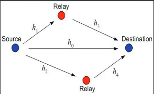
Cooperation happens when a direct communication between a source and destination is improved due to the help provided by neighboring node. This neighboring node is known as relay.
Fig. 1: The Cooperative Relay Network, Also Known as the Relay Channel
Data broadcasted by source is received by destination by direct transmission and/or via one or more relay. By combining the copies of data received directly and/or via independent relays, destination
node exploits the benefits of spatial diversity which improves the
performance of wireless transmission. In wireless communication, quality of service (QoS) at physical layer is measured in term of bit error rate (BER) or throughput, which can be improved with cooperation among users. In conventional data transmission, all bits in a symbol are treated in similar manner, having same bit error rate (BER) performance. In order to provide differential service at physical layer, the bits in a symbol can be divided
into layers using scalable modulation [2-3]. Potential benefits of
cooperative communication include performance enhancement at physical layer such as improved channel reliability, improved system throughput, seamless service provision, and operational cost reduction [3].
In cooperative wireless transmission network, transmission can be received by many nodes in the vicinity of the source. These neighboring nodes play an important role in transmission by forwarding the data to the destination. Hence, multiple copies of data may be received at destination via different relays nodes. Because of continuous variation in channel parameters, each individual copy of data experience different types of fading and interference. Multiple copies of same data received at destination provide a kind of spatial diversity. Depending on the level of signal processing performed at the relay, cooperative relaying scheme
can be classified as follows,
Amplify and forward
•
Decode and forward
•
Amplify and forward- as the name suggests, the Amplify and forward technique simple amplify the signal received by the relay before forwarding it to the destination. This technique is ideal when the relay station has the minimal computing power. However, one major drawback of this technique is that the noise is
the signal is also amplified at the relay station, and the destination
Fig. 2: Amplify and Forward Technique
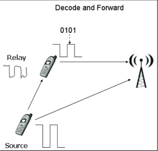
Decode and Forward- Decode and Forward method is a Digital relaying method. It is most preferred method of processing data in the relay nodes, and is closest to the idea of a traditional relay. In this the relay detects the source data, decodes and then transmits it to the desired destination. An error correcting code can also be implemented at the relay station. If the resource and performance constraints permit, digital relays can also decode and re-encode the received data. This could help the received bit errors to be corrected at the relay station. However, this is only possible when the relay station has the enough computing power. This way some of the errors occurring at the source relay link can be corrected at the relay [5].
Fig. 3: Decode and Forward Technique
Adaptive modulation and coding (AMC) - To improve the
spectral efficiency of cooperative diversity systems, adaptive
modulation uses [6]. In Adaptive modulation, Signal to Noise Ratio (SNR) of a wireless link varies with time. The qualities of signal received at destination deteriorate with increase in the distance between source and destination. Adaptive modulation and coding scheme (AMC) have been used to improve the system throughput in time varying wireless channel [7]. The power of the
transmitted signal is held constant over a frame interval, and the modulation and coding format is changed to match the current received signal quality or channel conditions. In AMC, the wireless channel is monitored continuously and based on the prediction of channel condition, transmitter selects the appropriate modulation
and coding scheme which maximizes the throughput while keeping
the Bit Error Rate (BER) below threshold value.
Network modulation and Scalable modulation – Scalable modulation scheme (SM) remaps the constellation of typical rectangular quadrature amplitude modulation (QAM) schemes using a software approach. Inspired by the scalable modulation, Network modulation scheme (NM) can be used as to enhance the throughput of a relay network. Network modulation gives us a new dimension to improve wireless network throughput and save energy. Scalable modulation having bits in a symbol can be divided into layers to provide differential priorities to the bits. Bits with higher priority are mapped into base layer which can be decoded by all the users. Bits with lower priority are mapped into enhancement layer and can be decoded only by targeted users [6].
In current wireless systems, when a source transmits data to the receiver through a single-hop or multi-hop wireless path, the physical layer modulates and demodulates the information bits hop-by-hop, and the transmission over each hop is treated the same as in a point-to-point communication link. Network
modulation is a software mapping technology, is using to redefine
the constellation of typical Quadrature Amplitude Modulation (QAM) scheme when a source transmits the data to multiple receivers simultaneously and when given the broadcast nature of wireless medium and the quality of wireless channel is of wide variation. In any relay network, there should be at least three nodes for apply network modulation.
Scalable modulation scheme can be used in wireless video multicast in order to provide different video quality to different users. Network modulation can be used to improve network performance in a wide range of scenarios, for anycast (broadcast, multicast and unicast) services, NM can also be used in one-way
or two-way traffic and single-hop or multi-hop wireless paths, in
infrastructure or ad hoc networks.
II. Related Work
In this paper, we propose a network modulation scheme inspired by Super-Positioning Precoding (SPC). It was designed for multicast transmissions and now recently it is using for relay communication [8-9]. Although SPC is not desirable for wireless devices because it
requires specialized hardware and sophisticated signal processing
techniques. But here in cooperative communication, data is transmitted by a single user may be destined for more than one receiver. Due to different channel condition of these channels, use of AMC is inappropriate. So here we are using Super-Positioning Precoding (SPC) scheme has been proposed to improve the
spectrum efficiency of broadcast channels [10]. Using SPC, a
transmitter can send data to multiple users by superpositioning the data targeted to different receivers in a single time slot. Here we
are going to explain an example of SPC in fig. 4, in the example where a source is transmitting one bit to first user and two bits
to second users. Instead of transmitting the bits in different time
slots, signal constellation is modifies in such manner that bits for
Fig. 4: Super-Positioning Precoding
After receiving the signals, each receiver can decode bits targeted to it. However because of complex hardware requirement and signal processing, SPC is not desirable for portable wireless devices.
In this paper, we are proposing a new approach to improve wireless network by using network modulation. It is based on software bit remapping, NM scheme can be implemented using existing transceiver hardware. Modulation type is chosen on the basis of
channel quality to maximize the data rate under the constraint
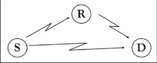
that the Bit Error Rate (BER) is below a threshold. If we discuss about signal to noise ratio, is different for different channels. In this paper we are presenting a three node scenario. These three nodes are source, destination and relay. Here one node works as a relay node between source and destination nodes. According to SNR information of different channel in the network a method is
presented to choose best scalable modulation scheme to maximize
the network throughput.
Fig. 5: Three Node Network
In traditional relay transmission, R forwards all bits of data to D hence, erroneous copy of data and direct transmission from S is received at D, is wasted completely. Here in paper [12], Network
modulation has been described for utilizing this erroneous copy
of data. In NM scheme, points in typical rectangular QAM are divided into clusters in such manner that D can demodulate some bits of received symbol and R can demodulate all bits of received symbol correctly. Now, instead of forwarding all bits to D, R relays only those bits which cannot be decoded correctly by D in direct transmission from S. In NM, bits represented by a symbol are divided into layers. Bits of layer one (L1) are demodulated by D and bits of layer two (L2) are demodulated by R.
Fig. 6: Decision Region for L1 and L2 Symbols for a Sample NM Scheme
In paper [11], NM constellations are using QAM and only five NM
constellations are examined using 16, 64 and 256 QAM. In [11],
[12], while considering the BER constraint 10-3, five NM scheme
have been presented. For each symbol transmission, S selects one of these NM schemes and R selects a typical QAM such that
overall throughput is maximized while keeping the BER under 10-3. In this paper, objective is to design new constellations to
improve the throughput while considering same BER requirement and channel SNR an in [11-12].
Wireless Channel Model- Data rate of wireless transmission depends on symbol rate and coding techniques. for simplicity, it is assumed that all channels have same symbol rate and error code sothat link data rate can be easily determine by the modulation scheme employed. In broadband wireless communication system, AMC has been widely used. Number of bits in a symbol depends on the modulation scheme chosen, while keeping the BER below threshold, the highest modulation scheme is chosen by transmitter according to the received SNR for each transmission.
Wireless signal suffers from path-loss, multipath fading, and other impairments during propagation. Path loss can be calculated using Friis free-space model. Free-space path loss is proportional to the square of the distance between the transmitter and receiver, and also proportional to the frequency of the radio signal.
The equation for free space path loss (FSPL),
(1)
Where,
λ is signal wavelength (in meters),
f is the frequency (in hertz),
d is the distance from the transmitter (in meter),
c is the speed of light in a vacuum.
The Friis transmission equation gives the power received by an
antenna under idealized conditions given another antenna, which is
positioned at some distance away, transmitting a known amount of power [11]. Let’s denote k as path-loss factor at reference distance
d0. It can be calculated using Friis free space model,
(2)
Given the transmission power Pt the received power Pr at distance d can be calculated as [12].
(3)
Where α is the path-loss exponent, which is a constant with values from 2 to 6 typically. Β is channel fading and shadowing factor,
which is a random variable and can be estimated using training
sequences. For simplicity, here β is taken as 1 for all wireless
links.
The received SNR γ,
(4)
Where, N0 is the background noise power, and γ0 is the received SNR at the reference distance d0.
Quality of channel between sources to relay varies with the location of relay. SNR of SR channel will be high when relay is nearer to source and will be less when relay is nearer to destination. According to SNR, ant one NM scheme is chosen for each transmission while keeping BER below the threshold value.
Throughput calculation- in a relay network for three nodes, overall throughput between source to relay can be calculated as;
Fig. 7: Here m1>m2>m
For traditional relay transmission using typical QAM, if S transmits ms bits per symbol duration (b/sym) to R and R forwards mR b/sym to D, then overall throughput between S to D is given in [12].
(5)
For NM transmission, if S transmits mS1 bits of L1 to D and mS2 bits of L2 to R in one symbol duration and R forwards mR b/sym to D, then overall throughput between S to D is given as [12].
(6)
Proposed NM Scheme- Design of NM scheme depends on channel SNR and BER requirement. Euclidean distance of intra-cluster points in NM constellation depends on SNR of S RD channel. Channel SNR of SR channel always higher than SNR of SD channel. hence of distance of intra cluster points is less than that of inter cluster points.
SNRSR> SNRSD
Considering same BER requirement as in [11], In this paper
presenting five new NM schemes. These five NM schemes are
NM_B1, NM_B2,NM_B3,NM_B4,NM_B5, Presented in this paper.
1. In NM_B1 scheme which is a modified 64QAM, the constellation
is divided into four clusters each cluster contains four symbols and each symbol represents 2 bits of L and 2 bits o L .
Fig. 8.1: Proposed NM scheme (NM_B1)
2. In scheme NM_B2, which is modified 64 QAM the constellation
is divided into two clusters. Each cluster contains four symbols and each symbol represents 1bit of L1 and 2 bits of L2.
Fig. 8.2: Proposed NM scheme (NM_B2)
3. In NM_B3 scheme, which is modified 64 QAM, the constellation
is divided into four clusters .each clusters contains two symbols ,and each symbol represents two bits of L1 and one bit of L2.
4. In NM_B4 scheme, the constellation is divided into four clusters. Each cluster contains four symbols and each symbol represents 2 bits of L1 and 2 bits of L2.
Fig. 8.4: Proposed NM scheme (NM_B4)
5. In NM_B5 scheme, which is modified 256QAM, the constellation
is divided into four clusters. each cluster contains eight symbols and each symbol represents 2 bits of L1 and 3 bits of L2.
Fig. 8.5: Proposed NM scheme (NM_B5)
For implementation and simulation analysis of proposed NM
scheme MATLAB 7.12.0(R2011a) have been used. For the
simulation of NM schemes, a linear topology is considered (as
below fig showing), where three nodes S,R and D are located on a
line segment . Distance between S and D is taken as d0=1 unit and relay node R moving from S to D. the transmission is subjected to Adaptive White Gaussian Noise (AWGN) and corresponding SNR at distance d0 from S is taken as 15.85 (12dB). Path loss
exponent α is set to 3, hence the received SNR at distance d is equal to 15.85 (d/d0)-3. The tolerable BER between S and D is
taken as pe= 10-3. Maximum throughput between S and D using direct transmission is 2 b/sym using quadrature phase shift keying (QPSK) [11].
Fig. 9: Linear Topology
The distance between S and R varying from 0.05 to 0.95 for
evaluate overall throughput under different channel conditions. According to channel SNR, any one NM scheme is chosen by S and typical and QAM chosen by R for each location of R. throughput is calculated, while keeping the BER between S to
D below 10-3.
Throughput for Proposed NM Scheme- In case of Network Modulation scheme, the constellation of modulated signal is divided into two layers, both offering the different BER performance. According to the channel condition we choose the best NM scheme
from a set of five NM schemes.
Following figure show the overall throughput of proposed NM
scheme transmission for Equal power allocation and for Optimal power allocation, respectively, while relay node R is moving from Source S to Destination D.
Fig. 10.1: Thoughput of Proposed NM Scheme for Equal Power
Allocation
Fig. 10.2: Throughput of Proposed NM Scheme for Optimal Power
III. Conclusion
It has been shown that by using five these new NM constellation
presented in this paper, throughput of a three node topology can be improved. Here, same average symbol energy has been used for every transmission. Hence, energy can also be saved by achieving higher throughput while spending same energy. Our results of this paper have shown that network modulation is applicable and desirable in many scenarios with the minimum of at least three nodes should be in the wireless communication. In network modulation, there can be generate other more NM schemes, which may perform better than proposed NM scheme of this paper and presented till now all the NM schemes.
IV. Future Work
Scope of NM scheme design is still under-explored. Design of an NM scheme depends on channel SNR and BER constraint. In
future, probability of error of these NM schemes can be verified
mathematically. In this paper, design of NM constellation is limited to QAM. NM constellation may also be designed using other modulation techniques. Network modulation can also be used simultaneously with network layer approaches such as Network
Coding (NC), which may improve the spectral efficiency.
References
[1] V.Mahinthan, L.Cai, J.W. Mark, X. Shen,“Partner selection based on optimal power allocation in cooperative-diversity system,” Vehicular Technology", IEEE Transactions on, Vol.
57, No. 1, pp. 511-520, 2008.
[2] W. Zhuang, M. Ismail,“Cooperation in wireless communication network,” Wireless communications, IEEE, Vol. 19, No. 2,
pp. 10-20, 2012.
[3] Singh,M., Trivedi, A.,“Throughput enhancement using network modulation in cooperative communication,” communication(NCC), Twentieth National Conference,
IEEE, pp. 1-6, Feb 2014.
[4] J. N.Laneman, G.W.Womell, D.N.C.Tse,“An Effective
Protocol for Realizing Cooperative Diversity in Wireless
Network,” Proc. IEEE ISIT, Washington, DC, pp. 294, June
2001.
[5] A. Meier,“Cooperative Diversity in Wireless Networks,”
MSc Thesis, University of Edinburgh, 2004.
[6] Jingning Wang, Xuezhi Tan,“Systems with adaptive
modulation technique,” National Basic Research program
of china, IEEE, pp. 1604-1606, 2011.
[7] C. Qian, Y. Ma, R. Tafazolli,“Adaptive modulation for
cooperative communication with noisy feedback,” In Wireless Communications amd Mobile Computing Conference
(IWCMC), 2011 7th International, pp. 173-177, 2011. [8] M. Butt, R. Zhang, S. Ng, L. Hanzo,"Superposition coding
aided bi-directional relay transmission employing iterative decoded self concatenated convolutional codes", In IEEE
VTC’10-Spring, May 2010.
[9] P. Popovski, E. De Carvalho,"Improving the rates in wireless relay systems through superposition coding", IEEE Trans
wireless Commun.,7(12), pp. 4831–4836, 2008.
[10] T. Cover, _Broadcast channels,_ Information Theory", IEEE
Transactions on, Vol. 18, No. 1, pp. 2-14, 1972.
[11] Z. Yang, Y. Luo, L. Cai,“Network Modulation: A new dimension to enhance wireless network performance”,
In INFOCOM, 2011 proceedings IEEE, pp. 2786-2794, 2011.
[12] Z. Yang, Cai, Y. Luo, J. Pan,“Topology-aware modulation and error-correction coding for cooperative networks,” Selected
Areas in communications, IEEE Journal on, Vol. 30, No. 2, pp. 379-387, 2012.
[13] Hua-An Zhao,“Adaptive modulation for cooperative wireless communication systems”, Signal processing,communicatiobs
and computing (ICSPCC),2014 IEEE International conference, pp. 102-105, August 2014.
Praveen kumar Singh received his bachelor of Engineering degree in “Electronics and communication” from “Rajiv Gandhi Prodyogiki Vishwavidyalaya Bhopal Madhya
Pradesh India” in 2010. He worked as
a BTS installation and commissioning engineer in “Blues tele- technologies
pvt ltd Gwalior India”, and was certified
as site commissioning supervisor by
ZTE china upto year 2012. He has done