Page 112 www.ijiras.com | Email: [email protected]
Designing Of Green Building Envelope By Using Trade-Off Method
Ar. Kajal Sharad Kanase
M.Arch IIIrd Semester, Environmental Architecture, Institute of Design Education and Architectural Studies, Nagpur
I. INTRODUCTION
When build green building, it will take affordable housing to the next level of performance. It will give owners and residents more comfortable homes that cost less to operate, last longer and keep occupants healthy. It will keep current with leading building techniques and gain valuable experience with a team approach that improves design and construction. And of course, it will help improve our environment as buildings become more efficient, use less resources, and reduce their impact.
A building envelope is the structural barrier between the interior and exterior of a building. It is responsible for maintaining climate control within the interior of a building. Climate control refers to cooling and heating a building. Green building offers us tremendous opportunities to save energy, cut greenhouse gas emissions, conserve natural resources, improve air and water quality, and reduce waste. The term "green building" is used to describe buildings that are designed, constructed, and operated, to have a minimum impact on the environment, both indoor and outdoor. Most discussions of green buildings refer to the importance of
providing an acceptable, if note exceptional, indoor environment for the building occupants. However, these discussions of indoor environment quality have not included many specific recommendations or criteria for building design, construction, or operation.
From ancient period, Building were constructed with low embodied material which was locally available and have low energy required, like stone, soil, thatch / leaves timber etc. But in modernism we used High embodied energy material which have to import or extract or required high energy to manufactured and also these are not ready to use, like brick, metal, glass, steel, cement, concrete etc. The choice of building materials can have multiple effects on a building’s energy consumption over the different phases of its life cycle. As the Indian construction industry is the largest producer of materials when compared to any other industry including agriculture, the higher utilization of energy in construction sector will eventually release Green House Gases. When sustainability is the driving force in the creation of building we need additional knowledge to assist them in making decisions about the choice of building material and the way in which they are used.
Abstract: Reducing negative impact on building and the natural environment is the main objective of sustainable design that promotes the environmental quality and the quality of building, which is mainly related to the envelope design of the building. The term "green building" is used to describe buildings that are designed, constructed, and operated, to have a minimum impact on the environment, both indoor and outdoor. In addition, rating systems that have been developed to assess the "greenness" of a building are based largely on design features and are not particularly specific with respect to indoor air quality. The assembly of exterior partitions of a building which enclose conditioned spaces, through which thermal energy may be transferred to or from the exterior, unconditioned spaces, or the ground. This paper highlights the use of various thermal resistance material, and the various approaches in the design of green building, The Envelope Trade-off Method in the Energy Conservation Building Code (ECBC) in India, is one way in which designers can use the prescribed Envelope Performance Factors (EPF) to measure how efficient their building envelope is, relative to a baseline envelope.
Page 113 www.ijiras.com | Email: [email protected] AIM
To gain confidence that the decisions to be made are the right ones for the DM, it is important to understand the trade-offs related to different optimal solutions.
OBJECTIVES
To enhance the healthy and comfortable interior environment.
To measuring the efficiency of building envelope. To develop knowledge and practice on issues concerning aspects of building design, technology, energy and environmental performance.
II. BUILDING ENVELOPE
When designing the building envelope, knowing some fundamentals of building materials and heat transfer will help you make the right trade-off decisions. The 20th century developments introduced new materials and technologies which widened the scope of design options in building envelopes. But as a result, buildings came up with large areas of windows which led to uninterrupted ingress of solar heat causing discomfort in the interiors. Such enormous amounts of solar heat gains had to be countered with the use of artificial means of cooling, which in turn increased the energy consumption of buildings.
III. COMPONENTS OF A BUILDING ENVELOPE A building envelope or the façade of a building can be categorised into Opaque and Transparent Components. The Opaque components comprise of Walls, Roofs, basement walls and doors which are not glazed. Transparent components consist of Windows, ventilators, skylights and completely glazed and half glazed doors.
Opaque components form the major part of a building envelope. Therefore, their surface area, thickness, selection of materials, colour and finishes are very important so as to limit the ingress of amount of heat gain. The thermal transmittance of materials of opaque components is generally described as U-value with units as W/m²K(Watts per meter squared Kelvin). it is preferable to have low U-value materials for better thermal performance of an envelope component.
Transparent Components consist largely of windows with glazing, which act as a medium of visual connection with the outdoors and to permit daylight into the interiors. But windows are most vulnerable to the solar heat gains and transmit a huge amount of solar radiation if suitable energy efficiency measures are not taken into account. The glazing
properties are described in terms of Solar Heat Gain Coefficient (SHGC) and U-value of complete fenestration systems (including frame and glass). SHGC values are taken between 0 and 1, which indicate the heat resistance capacity of a glass. Lower SHGC and U-values are generally preferred for energy efficiency. The other term associated with glazing properties is the Visible Light Transmittance (VLT) which varies between 0 to 1 and depicts the clarity of glass for daylight transmittance. The glasses having high VLT can although lead to glare issues.
IV. ENERGY FLOWS
Envelope energy flows from an energy flow perspective, the envelope is a composition of layers with varying thermal and permeability properties. The envelope may be composed of membranes, sheets, blocks and preassembled components. The choice of envelope is governed by the climate, culture, and available materials. The range of choices in envelope design can be illustrated by two opposite design concepts: the open frame and the closed shell. In harsh climate, the designer frequently conceives the building envelope as a closed shell and proceeds to selectively punch holes in it to make limited and special contact with the outdoors. This may also be true where unwanted external influences such as noise or visual clutters are. When external conditions are very close to the desired internal ones, the envelope often begins as an open structural frame, with pieces of the building skin selectively added to modify only a few outdoor forces. The flow of heat through a building envelope varies both by season (heat always flows from hot to cold and generally flow from a building in winter and to a building in summer) and by the path of the heat (through the materials of a building’s skin, or by outdoor air entering). These complexities must be considered by a designer who intends to deliver comfort and energy efficiency.
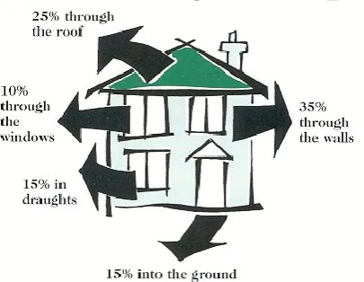
V. HEAT LOSS MYTHS (THROUGH BUILDING ENVELOPE)
Page 114 www.ijiras.com | Email: [email protected]
Figure 1: sustainablebuildingledell.blogspot.com
The proper use of air barriers and sealants eliminates or reduces this heat loss. This is not however the only manner of heat loss. Heat also moves via conduction and radiation. Conduction occurs when heat travels through solid matter, from an area of higher temperature to an area of lower temperature until a uniform temperature is achieved.
Radiant heat losses occur when electromagnetic radiation is released from hot matter (the filament of light bulbs, element in electric heaters or combustion of fuel). This radiation travels in a straight line from it’s source and radiates out like light (which is a form of radiation as well).
VI. PERIODIC HEAT TRANSFER THROUGH WALLS AND ROOFS
Heat transmission through the walls and roofs of building structures is not steady and is therefore, difficult to evaluate. The two principal factors causing this are:
The variation of the outside air temperature over a period of 24 hours.
The variation of the solar radiation intensity that is incident upon the surface over a period of 24 hours. In nature the variation of climatic conditions produces a non-steady state. Diurnal variations produce an approximately repetitive 24-hour cycle of increasing and decreasing temperatures.
The effect of this on a building is that in a hot period, heat flows from the environment into the building where some of it is stored, and at night during the cool period, heat flow is reversed from the building to the environment. As the cycle is repetitive, it can be described as periodic heat flow.
Figure 2: https://www.greenbuilt.org/natural-building/
India is experiencing an unprecedented construction boom. Buildings account for near about 35% of total final energy consumption in India today, Studies have shown that carbon policies will have little effect on reducing building energy demand. If there are no specific sectoral policies to curb building energy use, final energy demand of the Indian building sector will grow over five times by the end of this century, driven by rapid income and population growth. The growing energy demand in buildings is accompanied by a transition from traditional biomass to commercial fuels, particularly an increase in electricity use. This also leads to a rapid increase in carbon emissions and aggravates power
shortages in India. Growth in building energy use poses a challenge for the Indian government. To curb energy consumption in buildings, the Indian government issued the Energy Conservation Building Code (ECBC) in 2007.
VII.COMPLIANCE APPROACHES FOR DESIGNING GREEN BUILDING AS PER ECBC
There are three compliances used for designing green building as per building rating system.
Prescriptive method. Whole – building method. Trade – off method.
Trade off method applies to only building envelope. Of three methods, trade-off method can be used if one is concerned with the design of building envelope only, due to its inherent advantage.
Hence, in this paper trade-off method has been selected to illustrate the design of green building envelope.
VIII. BUILDING ENVELOPE TRADE OFF METHOD Calculation showing ECBC Compliance using Trade-off method
EPF Roof : Envelope performance factor for roof. Other
subscripts include walls and fenestration.
As ,Aw: The area of a specific envelope component
referenced by the subscript ‘s’ or for windows the subscript ‘w’.
SHGCw: The solar heat gain coefficient for window(w).
SHGCs refers to skylights.
Mw: A multiplier for the window SHGC that depends on the projection factor of an overhang
or sidefin.
Us: The U- factor for the envelope component referenced
by the ‘s’.
CRoof : A coefficient for the ‘roof’ class of construction.
CWall : A coefficient for the ‘wall’.
C1 Fenest : A coefficient for the ‘Fenestration 1’.
C2 Fenest : A coefficient for the ‘Fenestration 2’.
EQUATION
Page 115 www.ijiras.com | Email: [email protected] Climate: Hot and dry climate
Step 1: Determination of upper limit of envelope performance factor (EPF) for wall, roof and fenestration using prescriptive values:
A ) EPFRoof = URoof
Us = 0.261 (for 24 hr building)
As ( as per geometry ) = 50m X 25m
= 1250 m2
CRoof = ( for 24hr building in hot and dry climate)
EPFRoof = 25.98 X 0.261 X 1250
= 8475.97
B) EPFwall = CWall, mass + CWall,Others
(Note : In this case it has been assumed that there is no curtain wall)
Us = 0.440
As ( as per geometry )= 480 m 2
Cwall = 15.01 ( for 24hr building in hot and dry climate)
EPFwall = 15.01 X 0.44 X 480 = 3170.11
C ) EPFFenest = C1Fenest, North +
C2Fenest, North +
C1Fenest,south + C2Fenest,
south +
C1Fenest,Skylight + C2Fenest,Skylight
(Note : Assuming there is no skylight) Uw = 3.3
SHGC = 0.25 (since WWR<40%)
C1 Fenest, North = 56.09
C2 Fenest, North = -1.49
C1 Fenest, South = 81.79
C2 Fenest, South = 1.187
EPFFenest = 56.09 X 0.25 X 10 + (-1.49) X 3.3 X 10 +
81.79 X 0.25 X 30 + 1.187 X 3.3 X 30 = 821.98
EPFTotal = EPFRoof + EPFWall + EPFFenest
= 8475.97 + 3170.11 + 821.98 = 12468.06
Step 2 : Determination of EPF of proposed building actual U-factors and SHGC.
Assuming that in place of using URoof of 0.261, the roof of
proposed has U – factor of 0.3
EPF Roof new = 25.98 X 0.3 X 1250
= 9742.5
Similarly if U-factor of wall / fenestration and SHGC are different from prescriptive requirement, new EPFWall , EPFFenest
are to be calculated.
In this case, let us first assume that the wall and fenestration meet the prescriptive requirements.
The EPF of proposed building is :
EPFTotal new = 9742.5 + 3170.11 + 821.98
= 13734.59
Step 3 : comparison of EPF through perspective route and EPFNew through actual specifications show the later is higher
than EPFperspective, Hence the building is not complying with
the ECBC.
Step 4: Now even with the roof having U-value (0.4 against the requirement of 0.261), the EPF is to be brought
down to the level of EPFPerspective i.e. 12468.06 in this case.
This may be done by several options related to wall or fenestration.
In the example given above, through back calculation, it can be found that for bringing down the EPFNew to the level of
EPFPerspective = 12468.06 and with EPFRoof being 9742.5, and no
change in fenestration, (EPFFenest = 821.98), the maximum EPFwall
can be :
EPFWall new = 12468.06 – 9742.5 – 821.98
= 1903.58
Step 5 : For the target EPFWall new = 1903.58, the required
UWall new can be calculated through back calculation :
EPFwall = EPFwall = Cwall
UWall = 1903.58
15.01 X 480 = 0.264
This means that due to certain limitations, if in place of having U-factor of roof equal to 0.264, it is kept as 0.3, as one options, U-factor of wall can be improved from 0.44 to 0.266 for complying with the code. Similar to the method alternatives such as change in SHGC or change in UFenest can
also be explored. It is important to note that change in specification through ‘Trade-off method’ would vary from case- to- case and therefore need to be calculated separately for individual building and for individual solution.
IX. CONCLUSION
Building energy codes are one of the most cost-effective tools to achieve energy efficiency in buildings. Every new initiative has to face a lot of uncertainty.Developing a compliance evaluation system show the benefits of ECBC and build momentum for future implementation. Based on evaluation results, can develop the design and deal with design problems with help of ECBC implementation. Compliance evaluation also encourages the private sector to actively participate in energy code implementation. The evaluation methodology needs to define statistical methods for sampling and estimation, such as how to select representative buildings based on building type and size, location, and climate condition. Such projects help in clearing out the fog and make the way clear. This project has paved way for ECBC implementation in existing buildings as well as the proposed ones. ECBC implementation has been surrounded with a lot of questions since its inception. Help of live demonstration of such system is also useful approach for convincing those who are not in this space but are part of decision making process.
REFERENCES
[1] https://www.masterbuilder.co.in/energy-conservation-building-code-need-hour/
[2] http://pib.nic.in/newsite/PrintRelease.aspx?relid=165748 [3] Energy Conservation Building Code 2016,
Page 116 www.ijiras.com | Email: [email protected] [4] https://pdfs.semanticscholar.org/cfc4/55b6f3325923f18ba
c976056827fbbaadea6.pdf
[5] Project Trade-Off Decisions, https://www.irbnet.de/daten/ iconda/CIB19112.pdf
[6] ECBC Trade-Off Method Tutorial | Window | Architectural Designwww.scribd.com
[7] Time-Cost Trade-off Problem in Construction Project Management, Based on Fuzzy Logic - SciAlert Responsive Versionscialert.net
[8] Trade-Off Analysis Approach for Multiobjective Transportation Investment Decision Making | Journal of Transportation Engineering | Vol 141, No 3ascelibrary.org
[9] greenspree.ca at The Sietch » Heat Loss Mythsthesietch.org
[10]Shodhganga@INFLIBNET: Internt
systemfelshodhganga.inflibnet.ac.in
[11]Detecting Heat Loss Through the Envelopewww.buildings.com
[12]The Total Building Envelope Conceptwww.buildings.com [13]Sustainable | WBDG - Whole Building Design
Guidewww.wbdg.org
[14]Sustainable Buildingswww.sustainable-buildings-journal.org
[15](PDF) Design and Development of Sustainable Construction Strategy for Residential Buildings: A Case Study for Composite Climatewww.researchgate.net [16]