Abstract— Thanks to the technological advancement, the research in the autonomous aerial vehicle is growing and the prototypes configurations are developing. The quadrotor is one of Unmanned Aerial Vehicle (UAV). Increasing the capability of carrying a load and the endurance time of quadrotor are representing a challenge. In this paper, a new quadrotor model is designed and evaluated. This model is named VAL-quadrotor which based on varying the arms length to control the movements of attitude and position. VAL-quadrotor is designed to carry more load, by exploiting all motors power for carrying a load, while the attitude maneuverability Performed by using the arms length variation. In normal case without carrying the load this technique can exploit to increase the endurance time. The effect of the arms’ lengths is studied to select the appropriate length. Therefore, the simulation results proved that VAL-quadrotor possess the capability of carrying more load than the standard design.
Index Term-- Arm’s Length, PID controller, payload, Quadrotor, UAV
I. INTRODUCTION
Oneof the distinguished rotorcraft is a quadrotor, it has been attracted the interest of the researchers recently in all over the world. The challenge in Unmanned Aerial Vehicle (UAV) control and design encouraging researchers to develop this field, due to the broad field of application such as search and surveillance, monitoring the fire forest and rescues [1]. In spite of, the quadrotor has miniature size, simple mechanical structure, and easier to be controlled [2]. A quadrotor has an inherent capacity for take-off, flying, landing, and hovering[3]. This aircraft can plan and act at disaster place without risk the human life. Increasing the endurance and the payload ability will represent an important challenge. Improving any of these features will raise the performance of this aircraft. The standard quadrotor consist of four brushless DC motors fixed on the end of a cross frame, each motor produces a moment and a thrust force to control the flying of aircraft by varying the angular velocity of each motor. To increase the payload capability in the standard quadrotor either increase the propeller size or increase the propeller’s number [4]. Since, increasing the propellers size lead to increase the
1Yasameen Kamil N. is with mechatronics engineering school in
UniMAPand COEUAS, 02600, Arau, perlis, Malaysia ([email protected]).
2D.Hazry was with COEUAS, he is now member in COEUAS and the
dean of school of business in UniMAP, 02600, Arau, perlis, Malaysia([email protected])
3Khairunizam Wan and4ZuradzmanM.Razlan are withCenter of Excellence
for Unmanned Aerial system (COEUAS)andmechatronics engineering school in UniMAP, 02600, Arau, perlis, Malaysia
overall quadrotor’s size, while, increasing the number of propellers means increase number of rotors, this leads to increase the size of the aircraft and the power consumption. Where, in[4], a new design for quadrotor is proposed to increase the payload capability without affecting quadrotor size. Where, the propellers are positioned in a new shape to permit overlap, then it is achievable to use larger propeller in the design. In[5], a new configuration of quadrotor was proposed along with the criteria of appropriate selection of the modules which were accomplishing the requirements. This quadrotor is designed to satisfy carrying a medium weight of payload, increasing the flight time, and stable hovering. To control the stability performance, a PID control is developed in[6], the behavior of the quadrotor system is studied to obtain stability in flying the Quad-rotor, in order to develop a model of the vehicle as realistic as possible. In spite of this, the system has some transient perturbations especially in yaw movement, because of the simplification of controller design. In[7], the authors proposed the use of PID controller and LQ to control the flight of indoor quadrotor, it was detected that these controllers had the ability to stabilize the attitude of quadrotor in the presence of a disturbance.
The objective of this paper is to overcome the limitation of payload capability, by exploiting all motors power in carrying the payload and increase the endurance time in a normal case. In this paper, a new design and mathematical model VAL-quadrotor is proposed, where the variation in the arms lengths is adopted to control the attitude and position movements and perform the maneuverability. By exploiting the variation in the overall torque caused by varying arms length and fixing the motors’ speed, instead of that adopted in standard quadrotor achieved by varying motors speed and fixing the arms’ length. While increasing the payload over the standard quadrotor have the same features is implemented by exploiting all motors speed for carrying more load. Then, the maneuverability is performed by using the variation in the arms length. The arm’ length variation is performed by fixing stepper motor in each arm for increasing or decreasing the length of arms. Thus, a scenario is proposed for evaluation the appropriate model of the arm variation according to the fixed arm length; evaluate the performance of the quadrotor. This evaluation is done by adopting a new mathematical expression for the optimal choice of the arm’s length. The stability performance is achieved by using PID controller which is used in altitude, attitude, and position. The simulation model is implemented using MATLAB code to perform maneuverability and verify the behavior of VAL-quadrotor.
Payload Capability of VAL- Quadrotor Based
on PID Controller
1
This paper is arranged as, section II presents the VAL-quadrotor design, which consist of motion control of VAL- quadrotor and the aerodynamic force and moments of VAL-quadrotor, section III refers to VAL-quadrotor dynamic model, section IV is regarding system controller design which consists of altitude controller, attitude controller, and position controller design, section V presents evaluation scenario for arm selection, section VI presents simulation results which consist of simulation results of selection the arm’s length and the simulation results of payload capability, and finally the conclusion is presented in section VII.
I. VAL-QUADROTOR DESIGN
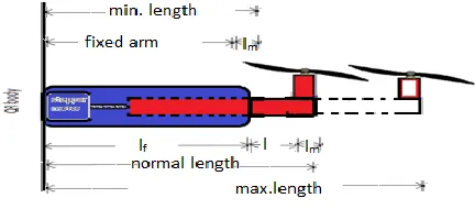
VAL-quadrotor design consists of four motors fixed on the end of four cross arms; each arm consists of two parts as
shown in Fig.1. The First part is fixed to VAL- quadrotor body
while the second part is sliding inside the fixed arm to increase or decrease the total length of the quadrotor arm. Stepper motors are fixed inside the fixed arm of VAL-quadrotor. Therefore, instantaneously the sliding arm slides out the fixed arm when the stepper motor rotates in C.W with constant speed and the total arm length increases. Conversely, the total arm length decreases when the stepper motor rotates in C.C.W and the sliding arm slides in the fixed arm. Where, the time variant during the variation of the arms’ lengths is overridden by the controller, this time is considered a disturbance to the system which can be neglected recently. Therefore, VAL-quadrotor has the ability to perform two flight modalities at a
short time, which essentially performs the movement as a
standard quadrotor and perform the movement as VAL-quadrotor
Fig. 1.The arm’s length design
A. Motion Control of VAL-Quadrotor
In this paper, controlling the movement of quadrotor depends on varying its arm’s length instead of the angular velocity of the motors while fixing the motors speed. This produces a variable moment around the quadrotor center of mass which directly controls the moment of the rotational movement in pitch, roll, and yaw while indirectly controls the x and y- position to accomplish the required maneuverability. Therefore, to model the VAL-quadrotor some important assumptions must be considered as
The angular velocity of each motor fixed to be
constant after reach desired altitude.
The arm’s lengths are varying according to thedesired movement during the flight
.
The thrust coefficients for all motors are constant.
Fig.2 (a) shows the pitch angle Ө about the y-axis, that can
be controlled by increasing the arm’s length related to M3 and
decreasing the arm’s length related to M1 and fixed all motors
speed, with the indirect control of the motion along the x- axis.
Fig.2(c) shows the roll angle
about x-axis which is thesame as pitch angle except that the roll angle is increasing the
arm’s length related to M4 and decreasing the arm’s length
related to M2 with the indirect control of the motion along the
y- axis.
Finally, yaw angle
about the z-axis can be controlled byincreasing the arm’s length of two related motors which rotate clockwise (M2 and M4), and decreasing the arm’s length of two related motors which rotate counter- clockwise (M1 and M3). Therefore, quadrotor mismatches the balance in a moment and rotated in a direction of the greatest moment, according to the direction of the propeller rotation as shown in Fig.2 (e).
Fig. 2. VAL-Quadrotor‘s movements
B. Aerodynamic Force and Moments of VAL-Quadrotor
The aerodynamic force and moment are extracted from a combination of the moment and blade element theory[8]. As mentioned VAL- quadrotor has four motors with propellers. The applied power to the rotor shaft generate a net torque which results in a thrust, the forward velocity causes a drag force in the direction opposite the quadrotor motion. Where
the thrust (
f
)
and drag (D) forces are defined as in [9]:i
f
= C
r2
2 (1)Di= Cd
r2
2(2)
Where A represents the blade area,
represents the airdensity, r represents the radius of the blade, ω represents the
angular velocity of the propeller and
c
,c
d represent) ( ) , , ( 2 1 4 1 4 1 2 2 2 . ,
, Ax y z Mgz f D xy
C F i i i i z y x
total
(3)
Where the first term of (3) represents the frictional force on
quadrotor along x, y and z axes and
C
x,y,z represents the dragcoefficients and (
z
y
x
,
,
) represent the speed in x, y and z-axes respectively, M represent the total mass of the quadrotor,
g represent gravity, z represent the vertical motion. The total
torques which acting on standard quadrotor body as demonstrated in [9].
According to VAL-quadrotor design since fixing the angular velocity, the thrust and drag forces are equaled for all
motors,
(
f
1
f
2
f
3
f
4
f
)
and (D1=D2=D3=D4=D)respectively. Then the total torque expressed as:
(4)
l
D
l
l
f
l
l
f
yx
D
h
xy
R
T
i i i m m m m i i i mi i total
4 1 1 3 2 4 4 1 4 1 1)
1
(
)
(
)
(
)
(
.
)
(
)
1
(
Wherer
r
C
R
m
R
2
2 mil
represents the arm’s length from the pivot center to therelated motor as shown in Fig.3, Rm represents the rolling
moment, h represents the vertical distance between propeller
center and gravity center of the aircraft
Fig.3.Architecture and coordinate of VAL- quadrotor
II. VAL-QUADROTOR DYNAMIC MODEL
VAL-quadrotor consists of two coordinate frames as shown in Fig. 3, which are earth inertia frame and body- fixed frame.
The earth inertia frame coordinates are and the
body-fixed frame coordinates are .The orientation
of quadrotor is represented by the attitude Euler angles which
are the roll, pitch and yaw angles (ϕ, Ө, and 𝜓) around the x,
y and z- axis respectively. The transformation from the body
frame to the earth frame is represented by transformation
matrix E under the assumption of:
The quadrotor structure is supposed to be rigid and
symmetric.
The center of the mass and the origin of the body
frame are coincide
Where E is defined as in the matrix below as in [10].
E =
c
c
c
s
s
s
c
c
s
s
c
c
s
s
s
s
c
c
c
s
s
s
s
c
c
s
s
c
c
(5)Where
c
(),
s
() represent cos (.) and sin (.) respectively.The lift forces and the rotational moments in the body frame will be expressed as
4 10
0
i i bz y xf
f
f
f
f
(6)
)
(
)
(
)
(
3 1 4 2 2 4 1 3l
l
l
l
D
l
l
f
l
l
f
quadrotor is 6-DOF. The equation of motion of
VAL-quadrotor subjected to the force
f
and moment
describedusing Newton-Euler method as in[11]:
Mv
f
v
M
(7)
I
I
(8)Where represents the angular velocity in body frame I
represents the moment of inertia. M represents the total mass
of the air craft. The forces in the earth inertia frame can be expressed as:
f
f
f
f
z y xE =
(9)
c
c
s
c
c
s
s
c
c
s
s
s
f
i i
4 1M
k
y
(10)
z
k
Mg
c
c
f
s
c
c
s
s
f
x
k
c
c
s
s
s
f
z
k
f
y
k
f
x
k
f
z
y
x
i i i i i i z y x
2 4 1 3 4 1 4 1 1 3 2 1)
(
)
(
)
(
Where
k
1,
k
2,
k
3represent the drag coefficientsThe rotational movement in pitch, roll, and yaw angles can be described by using Euler form by substitute (4) in (8) and adding the gyroscope action caused by the rotation of rigid body, the gyroscope action caused by the rotation of the propeller[8] and the aerodynamic drag which opposite the motors torque[13]. VAL-quadrotor dynamic model of rotational movements will be:
)
11
(
)
(
)
1
(
)
(
)
1
(
)
(
6 4 5 4 1 4 1 1 3 4 1 4 4 1 1 2k
u
I
I
I
k
I
D
h
R
u
I
I
I
k
I
D
h
R
u
I
I
I
yy xx zz yy i i yi xi i xx zz yy i xx i xi yi i zz yy xx
Where
k
irepresent the drag coefficients, andu
1,4 3 ,
2
,
u
andu
u
the inputs to the system and defined as:(12)
l
l
l
l
d
u
l
l
b
u
l
l
b
u
f
b
u
i i
)
(
.
)
(
.
)
(
.
)
(
4 2 3 1 2 4 3 1 2 3 4 2 2 2 4 1 2 4 2 3 2 2 2 1 1
Where b and d represent the thrust and drag coefficients.
According to (12), u2, u3, and u4represent the control torques
those impacts the attitude and position movements. These control inputs substituted in (11).
III. SYSTEM CONTROLLER DESIGN
A.Altitude Controller Design
PID controller is used for controlling the altitude of the quadrotor by controlling the speed of four motors to reach the altitude required. The lift force required for takeoff must be greater than quadrotor full weight [2], Where the motors speed for hovering state is calculated as:
(13)
The error signal for this controller will be expressed as
ez = zd - zre f (14)
The dynamic model of altitude with the controller is
z d z i z
p
e
k
e
dt
k
e
k
z
M
-Mg(15)Where
k
p,
k
i,
k
d represent the proportional, integral, andderivative gain respectively, which must be positive values.
B.Attitude Controller Design
For designing the attitude of quadrotor, a PID controller is also used. Pitch attitude is performed by increasing the arm’s
length of the motor (l3) and decreasing the arm’s length of the
motor (l1), while fixed the other two arms length and the
motors speed are also fixed. Finally, the pitch attitude controller error signal will be expressed in the equation below.
ref d
e
(16)
The PID controller equation for pitch attitude is:
k
e
k
e
dt
k
e
u
p i d (17)The equation of rotation for a quadrotor around y-axis includes PID controller and neglect the gyroscope effect [7] will be:
̈
(18)
Similarly for other attitude angles (Roll and yaw) the error signal will be:
ref d ref d
e
e
The PID controller equations for roll and yaw attitude are:
e
k
dt
e
k
e
k
u
e
k
dt
e
k
e
k
u
d i p d i p (19)The equations of roll and yaw attitude include PID controller will be:
̈
𝜓̈
C.Position Controller Design
The horizontal motion in x and y- axis can be accomplished by controlling the position of the quadrotor. Position control can be achieved by pitching or rolling VAL-quadrotor, and track the desired waypoint from x and y-axis. PID controller with saturation function is used for position control. From the position controller calculating the desired acceleration (
d
d
y
x
,
), as in[11].
ref d y
ref d x
y
y
e
x
x
e
(21)
(22) e
k dt e k e k y
e k dt e k e k x
y d y i y p d
x d x i x p d
Where (
x
d,
y
d) represent the waypoints desired, (x
ref,
y
ref)represent the reference positions and
k
p,
k
i,
k
drepresent theproportional, integral, and derivative controller gains respectively. The desired pitch and roll angles are calculated
from the desired acceleration
x
and
y
from (10).(23)
(24)
As considering VAL- quadrotor is under hover condition.
Thus,
sin
d
d,
sin
d
d andcos
d
cos
d
1
Then, from (23)and (24) can find the desired roll ( ) and
pitch ( angles as in[14].
d d
d d
y x u
m
1 1
sin cos
cos sin
(25)
The desired angles
d,
dmust be limited to the rangesthat ensure the condition of small angles [14] above. This can be done by using saturation function which is.
)
(
)
(
d d
d d
sat
sat
(26)
Where
Sat(k)=
max max
max
)
(
k
k
k
k
sign
k
k
k
(27)
And
Sign (k) =
0
1
0
1
k
k
(28)
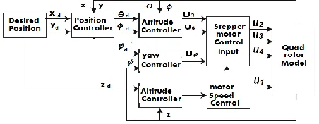
In VAL-quadrotor design, the system is divided into altitude subsystem, attitude subsystem and position subsystem as in Fig. 4. Two microcontrollers are used in VAL-quadrotor. One for controlling the speed of motors and the second for controlling the stepper motors. The full control block diagram can be illustrated as in following block.
Fig. 4. Block diagram of VAL- quadrotor full control
IV. EVALUATION SCENARIO FOR ARM SELECTION A new mathematical expression is designed to calculate the rate of change in the arm, and the amount of increasing in one or more arms and decreasing the relative arms that realized a
specific movement in the quadrotor.
max )
( )
(lf lml L lf lm L (29)
min )
( )
(lf lm l L lf lm L (30)
Where( lf ) means the length of the fixed arm,( lm)the
diameter of the motor,(l) additional length to give flexibility to
arm for sliding, all this called the normal arm, ( ∆L) is the rate
of change of the arm to verify maximum Length and minimum length as shown in Fig. 1
V. SIMULATION RESULTS
A.Simulation Results of Selecting the Arms Length
A scenario is proposed to evaluate the appropriate arm’s length and selected in the design of attitude movement, when VAL-quadrotor oriented from 0 rad to the desired value (0.35rad).
As assumption of the fixed arm is equal to17.5cm and the total arms varying between 20cm and 30 cm for minimum and maximum length of the arms, respectively. By solving
(29)and (30) for these values, l = 5 and ∆L=0.25. Then, the
range of ∆L is 0 <∆L ≤ 0.25. Table I explained the rate of
change (∆L) and its effect on the arm’s length.
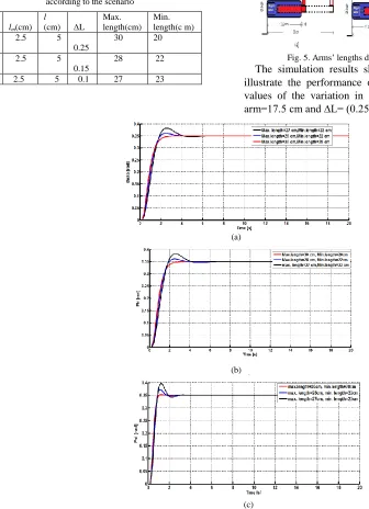
Therefore, Fig. 5 (a), (b) and (c) show the response of the
arms according to the value of ∆L which is equal to 0.25, 0.15
and 0.1 respectively
sin sin cos cos sin
cos sin cos sin sin
1 1
d d d
d
d d d
d
m u y
m u x
TABLE I
Varying the rate of change (∆L), maximum length and minimum length according to the scenario
Fig. 5. Arms’ lengths design according to the scenario
The simulation results shown in Fig. 6 (a), (b), and (c) illustrate the performance of three attitude angles for three values of the variation in the arm’s length when the fixed arm=17.5 cm and ∆L= (0.25, 0.15, 0.1).
(a)
(b)
(c)
Fig. 6. The response of (a) roll angle, (b) pitch angle, (c) yaw angle according to variation in the arm
According to the results of scenarios, the first choice in Table I is preferable for the arm’s length design of VAL-quadrotor, due to the accuracy and the fast response of the performance.
TABLE II Speed/mass values. Desired altitude
(meter)
Speed of motor(rad/sec)
The lifting mass(kg)
10 192 0.5
10 272 1
10 333 1.5
10 385 2
10 421 2.4
10 500 3.37
B. Simulation Results of Payload Capability.
For evaluation results, a simulation framework in MATLAB code is developed that meets the design requirements. The physical parameters that used for the
simulation results are: M=2Kg, gravity=9.81m/s2,b=3.31×10-5,
d=7.5×10⁻⁶,arm’s length= according to the first choice of
Table I Ix=Iy=1.25Ns2/rad, Iz=2.5Ns2/rad, k1= k2=
k3=0.010Ns/m, and
K4= k5= k6=0.12Ns/m.
The total mass of the system is equal to 2kg. To reach the desired altitude, the total lift force must satisfy (13). Where the speed required for carrying this mass is equal to 385 rad/sec from each motor. According to Table II, to increase lf
lm(cm)
l
(cm) ∆L
Max. length(cm)
Min. length(c m) 17.5 2.5 5
0.25
30 20
17.5 2.5 5 0.15
28 22
the payload of the aircraft must increase the thrust generated by motors.
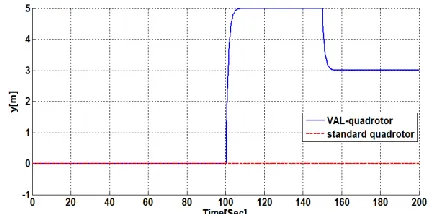
Since 500rad/sec are the maximum speed of the motors, then the maximum load carried by VAL-quadrotor is about 3.37kg to reach the desired altitude. Moreover, as the maximum speed is fixed to reach the desired altitude, VAL-quadrotor can perform the maneuverability by using the variation in the arms length according to the desired path as shown in Fig. 7. While, for500rad/sec maximum speed, the standard quadrotor can carrying a load equal to 2.4kg to perform the maneuverability. Where, the maximum speed for hovering with this load is equal to 421rad/sec and the remainder 15% of the maximum speed for performing the maneuverability in x, y-axis [15]. If the carrying load is increased to reach 3.37 kg, the standard quadrotor reached the desired altitude and cannot perform the maneuverability, due to exploiting maximum motors speed for carrying a load as shown in Fig. 7. Where in Fig. 8 the standard quadrotor can reach the desired altitude and hovering at this height. As well as, it cannot perform the maneuverability as shown in Fig. 7 Fig. 9, Fig. 10, Fig. 11, and Fig. 12. While VAL-quadrotor as compared with a standard quadrotor can track the desired path accurately with including payload and will possess a final weight equal to 3.37 kg
Fig. 7.Trajectory tracking due to the desired path for VAL and standard quadrotor, when the maximum motors’ speed =500rad/sec and mass=3.37kg.
Fig. 8.The altitude in VAL and standard quadrotor, when when the maximum motors’ speed =500rad/sec and mass=3.37kg.
Fig. 9. The x-position in VAL and standard quadrotor, when the maximum motors’ speed =500rad/sc and mass=3.37kg.
Fig. 10.Pitch angle in VAL and standard quadrotor, when the maximum motors’ speed =500rad/sc and mass=3.37kg.
Fig. 11.The y-position in VAL and standard quadrotor, when the maximum motors’ speed =500rad/sec and mass=3.37kg.
Fig. 12.The roll angle in VAL and standard quadrotor when the maximum motors’ speed =500rad/sec and mass=3.37kg.
VI. CONCLUSION
instead of varying the speed of the motors in standard quadrotor. A new mathematical model was derived using Newton-Euler method. The appropriate arm’s length was selected that designed according to the proposed mathematical expression. Feedback control system based on PID controller was presented that realized the stability of the quadrotor.
VAL-quadrotor in the presence of a controller can effectively improve the capability of payload about 40% of the standard quadrotor. While in the normal case (without carrying a load), VAL-quadrotor can increase the endurance time. In addition, the new design takes into account increasing the motor’s lifetime since the speed of motors still constant during the flight time. Therefore, the motor coils not affected by the thermal heating caused by increasing the motor speed to a high level. In contrary, the motors in standard design affected by the speed changing which reducing the
motor’s lifetime.
REFERENCES
[1] A. Puri, "A survey of unmanned aerial vehicles (UAV) for traffic surveillance," Department of computer science and engineering, University of South Florida, 2005.
[2] M. H. Tanveer, D. Hazry, S. F. Ahmed, M. K. Joyo, and F. A. Warsi, "Design of overall Stabilized controller for Quad-rotor."
[3] Y. Ming and X. Yunqing, "Design of Nonlinear Aero Controller and Simulation for Quadrotor Unmanned Aerial Vehicles," in Software Engineering (WCSE), 2013 Fourth World Congress on, 2013, pp. 283-287.
[4] G. Nandakumar, T. Ranganathan, B. Arjun, and A. Thondiyath, "Design and analysis of a novel quadrotor system-VOOPS," in Robotics and Automation (ICRA), 2015 IEEE International Conference on, 2015, pp. 1692-1697.
[5] J. A. Benito, G. Glez-de-Rivera, J. Garrido, and R. Ponticelli, "Design considerations of a small UAV platform carrying medium payloads," in Design of Circuits and Integrated Circuits (DCIS), 2014 Conference on, 2014, pp. 1-6.
[6] A. L. Salih, M. Moghavvemi, H. A. Mohamed, and K. S. Gaeid, "Flight PID controller design for a UAV quadrotor," Scientific Research and Essays, vol. 5, pp. 3660-3667, 2010.
[7] S. Bouabdallah, A. Noth, and R. Siegwart, "PID vs LQ control techniques applied to an indoor micro quadrotor," in Intelligent Robots and Systems, 2004.(IROS 2004). Proceedings. 2004 IEEE/RSJ International Conference on, 2004, pp. 2451-2456.
[8] S. Bouabdallah and R. Siegwart, "Full control of a quadrotor," in Intelligent robots and systems, 2007. IROS 2007. IEEE/RSJ international conference on, 2007, pp. 153-158.
[9] A. A. Mian and W. Daobo, "Modeling and backstepping-based nonlinear control strategy for a 6 DOF quadrotor helicopter," Chinese Journal of Aeronautics, vol. 21, pp. 261-268, 2008.
[10] D. Lee, H. J. Kim, and S. Sastry, "Feedback linearization vs. adaptive sliding mode control for a quadrotor helicopter," International Journal of control, Automation and systems, vol. 7, pp. 419-428, 2009.
[11] H. K. Kim, T. T. Nguyen, S. J. Oh, and S. B. Kim, "Position Control of a Small Scale Quadrotor Using Block Feedback Linearization Control," in AETA 2013: Recent Advances in Electrical Engineering and Related Sciences, ed: Springer, 2014, pp. 525-534.
[12] F. Sharifi, M. Mirzaei, B. W. Gordon, and Y. Zhang, "Fault tolerant control of a quadrotor UAV using sliding mode control," in Control and Fault-Tolerant Systems (SysTol), 2010 Conference on, 2010, pp. 239-244.
[13] L. R. G. Carrillo, A. E. D. López, R. Lozano, and C. Pégard, "Modeling the quad-rotor mini-rotorcraft," in Quad Rotorcraft Control, ed: Springer, 2013, pp. 23-34.
[14] A. Nagaty, S. Saeedi, C. Thibault, M. Seto, and H. Li, "Control and navigation framework for quadrotor helicopters," Journal of intelligent & robotic systems, vol. 70, pp. 1-12, 2013.
[15] P. T. Nathan and H. A. Almurib, "Optimization of nonlinearities through control techniques of the quadrotor aerial vehicle," in Modeling,