e-ISSN: 2278-067X, p-ISSN: 2278-800X, www.ijerd.com
Volume 13, Issue 2 (February 2017), PP.62-66
Digitally Programmable Versatile Grounded Multiplier Using
CCII
N. Afzal
Department of Electronics and Communication Engineering,Jamia Millia Islamia,New Delhi, India
ABSTRACT
:
A novel digitally programmable grounded versatile multiplier is presented. It uses second generation current conveyor and a digital control module. The new grounded versatile multiplier can provide digital control to grounded impedance functions such as, resistor, capacitor, inductor without quantizing the signal. The technique used is simple, versatile as well as compatible for microminiaturization in contemporary IC technologies. The simulation results on digitally programmable versatile impedance multiplier verify the theory.Keywords
:
current conveyors; multiplierI.
INTRODUCTION
Second generation current conveyors (CCIIs) is widely used analog building block for realizing analog signal processing circuits. It is functionally flexible and versatile building block which possess higher signal bandwidth, greater linearity, large dynamic range, low power consumption and most importantly the feasibility of integration [1-2]. As a result it is gaining wide acceptance as a building block for designing voltage/current mode analog signal processing circuits [3-6]. In the mixed signal systems the on chip control of the systems’ parameter can be provided through digital means with high resolution capability and the reconfigurability [4-8].
In this paper a novel digitally programmable grounded versatile multiplier (DPGVM) using second generation current conveyor is presented. To demonstrate the versatility of the DPGVM, digitally controlled grounded positive and negative resistor(R), capacitor(C) and inductor are realized. The circuit consists of a CCII, a digital control module (DCM), which is realized using R-2R ladder and n-bit switching array, along with impedance under control. The realized DPGVM is simulated for positive and negative resistors using PSPICE.
II. DIGITAL CONTROL MODULE
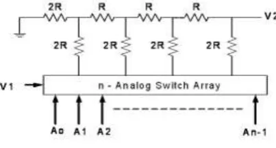
The realization of the digital control module (DCM) used in the DPGVM is shown in Figure 1(a), which uses R-2R ladder and analog switching array [7]. Its routine analysis yields the output voltage V2 as
1
1 2
1 0 1
2 2 4 2
2
n
n
n A A A A
V
V (1)
Where, A0, A1, …, An-1 are the bit values of the n-bit digital control word (N). Equation (1) can also be
expressed as
V2 K1V1 (2) Where, K1 = N/2
n
Figure 1(a): Single stage digital control module.
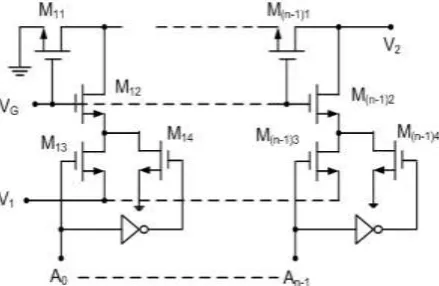
The CMOS implementation of Figure 1(a) along with the control switches is given in Figure 1(b). The W/L ratios of the MOSFETs are adjusted to meet the required resistance ratios. Figure 1(b) now onwards shall be expressed as the as single stage digital control module-K as shown in Figure 1(c). The channel resistance of the MOSFETs M13 and M14 can be included with the resistance M12 of the R-2R ladder to reduce the parasitic
Figure 1(b): CMOS implementation of Single stage digital control module
Figure 1(c): The K1 – Block.
If two stages of the K1- Block with same control word are cascaded through a voltage buffer as shown in
Figure 1(d),
The transfer gain can be expressed as
2
2 1 2
2
K
N
nV
V
(3)where, K2 = K1 K1 = (N/2n)2. Henceforth, this double stage block shall be referred as the K2 – Block. Its
equivalent is also shown in
Figure1(c). It is obvious from equation (2) and (3) that the transfer gain of the K1 and K2 modules can be
controlled through digital control word (N).
Figure 1(d): Double stage digital control module symbol.
III. DIGITALLY PROGRAMMABLE GROUNDED VERSATILE MULTIPLIER
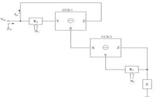
Figure 2: Digitally programmable grounded versatile multiplier
The routine analysis of Figure 3 yields its grounded versatile impedance function with two single stage digital control modules K1 and K2 as
Z K K I V Z in in v 2 1 (4) where, K1 = N1/2
n
and K2 = N2/2 n
. Thus, the realized impedance of equation (4) reduces to
Z N N ZV 2 1 (5) and with double stage digital control module-K2 as
Z N N Zv 2 2 1 (6)
It is to be noted that Zv is positive if the CCIIs used in circuit of Figure 3 are of same type i. e. both the
CCII are to be either positive type or negative type. The Zv is negative if the two CCIIs used in circuit of Figure 3 are of opposite type i. e. if one CCII is of positive type then other is to be of negative type. From equation (4) it is clear that the impedance seen at the input port of the Figure 3 can easily be controlled by the ratio of digital words N1 and N2, in turn the realized input impedance Zv is controlled. The terminating impedance Z may be
selected either resistor(R), capacitor (C) or inductor (L) or any combination of these components. Thus the digitally controlled positive as well as negative grounded versatile impedances are realized.
Case 1: Digitally Programmable Grounded Versatile
RIn Figure 2, if the terminating impedance Z is considered as resistor i.e., Z=R, equation (4) reduces to Zv = Rv
(7a)
With the single stage control module-K, the grounded versatile resistance from equation (5) reduces to:
R N N Rv 2 1 (7b)
With the double stage control module-K2, the grounded versatile resistance from equation (6) reduces to:
C N N Cv
2
1 2
(8c)
Thus it is obvious from equation (8) that grounded versatile capacitance(Cv) can be controlled inversely through
N1 and directly through N2.
Case 3: Digitally Programmable Grounded Versatile
LIn Figure 2, if the terminating impedance Z is considered as an inductor i.e. Z = sL, equation (4) reduces to Zv = s Lv (9a)
With the single stage control module-K, the grounded versatile inductance from equation (5) reduces
L N N
Lv
2
1 (9b)
With the double stage control module-K2, the grounded versatile inductance from equation (6) reduces to:
L N N Lv
2
2 1
(9c)
Thus by controlling the digital control words the realized grounded versatile inductance Lv is programmable
through N1 and N2.
IV.
SIMULATION RESULTS
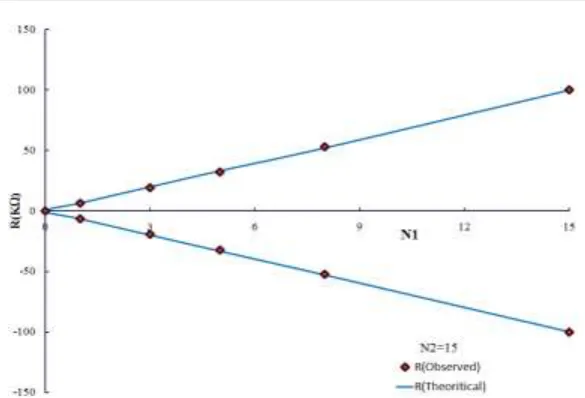
The practical validity, the proposed digitally programmable versatile Grounded impedance multiplier is simulated using PSPICE for
R. The 4-bit digital control module of section II is used. The voltage-current plot obtained from PSPICE simulation for digitally programmable versatile impedance grounded multiplier of Figure 2. with R=100KΩ for various N1 is given in Figure 3(a). Also, by varying the digital control word (N1) the grounded versatile resistance
R is controlled and the results obtained are shown in Figure 3(b), which clearly exhibits the responses in close conformity with the design.Figure 3(b): Variation of R with N1 for grounded positive and negative resistorkeeping N2=15.
V.
CONCLUSION
A novel digitally programmable grounded versatile multiplier is realized using two digital control modules and second generation current conveyors. It realized programmable positive and negative resistors, capacitors and inductors. It enjoys attractive features of digital tuning, low component count. grounded passive components, suitability for IC implementation. More number of bits can be used in digital control module to achieve higher resolution. The simulation results on the DPGVM verify the theory.
REFERENCES
[1]. Wilson, B., 1992. Tutorial review: Trends in current conveyors and current mode amplifier design. Int. J. Electronics, 73(3), 573-58
[2]. Svobodo, J. A., 1994. Transfer function syntheses using current conveyors. International Journal of Electronics, 76, 611-614.
[3]. D. Biolek, R. Senani, V. Bilokova, and Z. Kolka, Active elements for analog signal processing:classification, review, and new proposals, “Radioengineering, vol. 17, no. 4, pp. 15-32, Dec 2008.
[4]. Khan, I. A., and Maheshwari, 2000. Simple first order all pass section single CCII. International Journal of Electronics, Vol. 87, No. 3, pp. 303 - 306.
[5]. Alzaher, H., 2006. CMOS digitally programmable inductance, Proceeding ICM–06, pp. 138-141.
[6]. Al-Shahrani, S. M., and M. Al-Gahtani, 2006. A new poly-phase current-mode filter using digitally programmable current-controlled current conveyor, Proceeding ICM-06, pp. 142-145.
[7]. Khan, I. A., Khan, M. R., and Afzal, N., 2006. Digitally programmable multifunctional current mode filter using CCIIs. Journal of Active and Passive Devices. Vol. 1, pp. 213-220.