Abstract— In this paper, Computational fluid dynamics method is used to simulate the supersonic flow. Convergent-divergent (C-D) nozzle have been used with sudden expansion. The base pressure controlled by using the microjets of 1 mm of orifice diameter is arranged at ninety degrees at PCD 13 mm. The Mach number is 1.87, and the area ratio of 3.24 was considered for the present study. The L/D of the duct was used 10, and the nozzle pressure ratio (NPR) considered for simulation was from 3, 5, 7, 9 and 11. The two-dimensional planar model has been used using ANSYS commercial software. The total wall pressure distribution and Mach number variation from the inlet to the outlet was observed. From the results, it is found that the microjets are capable of controlling the base pressure, the loss of pressure and decreases in the drag. In the present study, the C-D nozzle designed and modeled: K-ε standard wall function turbulence model has been used and validated with the commercial computational fluid dynamics (CFD).
Index Term— C-D nozzle, Wall Pressure; Flow Control; NPR; CFD; Microjets.
I. INTRODUCTION
In engineering application, the sudden expansion of the flow in supersonic regimes is significant and has applications in many fluid flow problems. In rocket and jet engine test-cells systems have been used to simulate the upper atmosphere flow field; a jet discharging yields a low pressure which is very low as compared to the atmospheric pressure. However, CFD analysis has its advantage to simulate the flow field’s plays an important role in current technologies of design optimization by providing very accurate solutions for a given problem with different commercially available tools. Recently, Khan et al. identified the velocity and pressure effect in a suddenly expanded converging-diverging (C-D) nozzle flow for area ratio 6.25 [1], [2] and area ratio 3.24 [3] with and without the presence of the micro-jets at the base using the CFD.
From literature, it is found that CFD simulation by different available design and analysis tools have been used from the last two decades. Some of them are highlighted here; the CD nozzle used for convert pressure energy to kinetic energy in order to yield thrust using CFD method in various performance parameters [4]. CFD was used to optimize fluid flow in a supersonic rocket nozzle at a various divergent angle of the nozzle by using 2D axis-symmetric model [5]. The De-Laval nozzles were used to convert the thermal and pressure energy
into kinetic energy using the CFD software ANSYS Fluent and compared with theoretical results [6]. High-speed CD nozzle has been modeled and optimized the flow after the throat at a certain point using ANSYS FLUENT [7]. Numerical simulation has been used to optimize the flow in a convergent-divergent nozzle for Mach number M = 2.6 at nozzle exit using the RANS equations with k-ω SST turbulent model [8]. CFD simulation has been carried out to study the pressure and velocity affects for different designed Mach numbers, area ratios and length to diameter ratio of the CD nozzle [9]–[13]. Evaluating the optimum fineness ratio (ratio of length to maximum diameter) of the human-powered submarine of different shapes to reduce the drag force on the body using CFD simulation [14]. Numerical simulation was carried out for Box-wing configuration and simulated non-planar configuration using ICEM CFD and ANSYS CFX solver [15]. Investigated the flow-field by a numerical approach using CFD simulation to investigate the efficacy of the supersonic Mach numbers due to the flow from the supersonic nozzle exhausted in a larger circular duct [13].
From numerical simulation, the laminar flow in a sudden augmented pipe subjected to a uniform suction speed has been analyzed [16]. Different numerical methods have been used to solve and account the viscous effects of the flow and compared with the available results from the literature. It is concluded that along the length of the duct with the progressive increase in the values of blowing speed applied at the walls the vortices generated near the step wall dwindles. Furthermore, separation control using microjets has been examined in a canonical flow such as a modified backward facing ramp [17] and for aerospace applications for two-dimensional airfoils [18], [19]. Khan et al. [20]–[29] experimentally investigated the mechanism to assess the performance of the control mechanism by the small jets at various level of expansion to regulate the base pressure in a suddenly expanded circular ducts at moderate and high supersonic Mach numbers. The result thus produced showed that the highest gain in the base pressure by more than 100 percent for Mach number 2.58.
For C-D nozzle with sudden expansion, the variation in mean velocity profiles along x-axis where the four microjets are placed at the designed Mach number has been studied to identify the effects of the control mechanism [30]. An experimental investigation has been carried out to investigate
Sher Afghan Khan
1, Abdul Aabid
1, and C Ahamed Saleel
21Department of Mechanical Engineering, Faculty of Engineering, International Islamic University Malaysia,
Kuala Lumpur, Malaysia
the control of base pressure with and without the control in the form of the microjets with axi-symmetric suddenly expanded duct in the supersonic regime [31]. Experiments work has been conducted in order to investigate the base pressure variation from an axisymmetric nozzle having an exit diameter of 10 mm and Area ratio of 4.84 [32], [33]. This investigation focused attention on the outcome of the wind-tunnel tests conducted to control the base pressure in the recirculation region and also investigated the efficiency of the control mechanism to manipulate the base pressure in a suddenly expanded duct [34], [35]. The effects of microjets were investigated in a sudden expansion of air for different area ratio and L/D of the circular pipes, at subsonic and sonic flow regimes by [36]. Investigated the airflow from CD axi-symmetric nozzles expanded suddenly into the circular duct of larger cross-sectional area than that of nozzle exit area, focusing attention on the base pressure and the flow development in the duct [37]–[47]. A technique for estimating the efficiency of microjets in a flow which is exhausted into the large duct from a CD nozzle has been investigated. In the evaluation for low, medium and high Mach numbers, the pressure distribution of the flow behind the nozzle exit is computed, and the results indicate the presence of oblique shock, Mach waves, and expansion fan when the shear layer is exiting from the nozzle exit which depends upon the level of expansion [48]–[50].
To control base pressure at the sudden expansion static as well as the dynamic control cylinder has been used to regulate the base flows. The effect of the control mechanism has been identified when rotated clockwise inside the recirculation zone at different locations at the base region to reduce the drag. The study considered to control the base pressure for different Mach number, area ratio, L/D, and NPR. The study shows the effectiveness of the control mechanism to control the pressure with sudden expansion for CD nozzle, and it also discussed the effect of the low-cost base drag reduction technique [40], [51]– [61].
The objective of this paper is to investigate the flow field in a C-D nozzle. The parameters considered, in this investigation are the L/D ratio of 10, and the NPR considered are 3, 5, 7, 9, and 11 for an area ratio of 3.24. The flow-field is pressure and Mach number. The 1 mm orifice diameter microjets have been employed at the base of the nozzle to optimize the effectiveness of the control and the influence of the microjets on the flow development in the duct. The results have been shown using contours and base pressure as well as pressure plots for different NPR.
II. PROBLEM DEFINITION
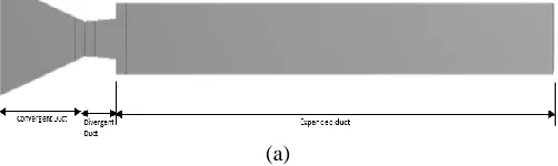
Figure 1 illustrates the designed CD nozzle for Mach number 1.87. Four microjets are used of 1mm of diameter and located at the pitch circle diameter of 1.3 mm. This study aims to analyze the pressure and Mach number flow for L/D 10 and different NPR using 2D CFD simulation with and without microjets. These microjets are operated at sonic Mach numbers
even though the stagnation pressure in the control chamber was very high. To generate supersonic flow instead of circular orifice we should have C-D shapes of the microjets.
Fig. 1. CD nozzle with enlarged duct
The procedure for the data analysis was followed as in Ref. [17]. In this paper, the step height is 3 mm having area ratio as 2.56, and the level of expansion in the control tank is similar to that of the storage tank. This research aims to study and quantify the possibility of the flow regulation where small jets are used as the blowing in the base area as the flow regulation mechanism for restraining the base pressure.
The dimensions of the CD nozzle with suddenly expanded duct are mentioned in table I.
Table I Dimension of CD nozzle
Mach Number 1.87
Inlet diameter (Di) 28.72
mm Throat diameter (Dt) 8.648
mm
Exit diameter (De) 10 mm
Extended diameter (D) 18 mm Convergent length
(Lc)
35 mm
Divergent length (Ld) 12.926 mm
Extended length (Le) 180 mm
Micro-jets diameter (Dm)
1 mm
III. FINITE ELEMENT METHOD AND ANALYSIS
Figure 2(a) illustrates the finite element two-dimensional planar model of CD nozzle and figure 2(b) illustrate closed of finite element meshing. ANSYS Workbench has been used and created a structural mesh, the number of elements has been used high to create the fine mesh in a closed area at the edge of the planar body. Total, 36,388 binary nodes, were generated for the 2D planar model.
(b)
Fig. 2: 2D planar fluid body (a) Finite Element Model (b) Meshing.
A. Setup for Solution Initialization
Computations of the flow field inside the control volume were done using RANS (Reynolds-Averaged Navier-Stokes) equations with the k-ε standard turbulent model [62].
The most important settings that have been applied are; • Solver: steady, absolute, 2D planar pressure-based • Model: viscous, k-ε standard wall function, the
Energy equation
• Fluid: air, ideal gas, viscosity by Sutherland law, three coefficient methods
• Boundary conditions: inlet, pressure inlet (pa); outlet, pressure outlet; wall, wall
• Solution method: Pressure (standard); density, momentum, turbulence kinetic energy, turbulence dissipation rate, energy (second-order upwind) • Solution initialization: standard, from inlet •
Reference value: inlet (solid surface body)
IV. RESULTS AND DISCUSSION
A. Validation of Finite Element Model
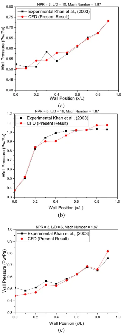
In order to validate the finite element (FE) results, the configuration considered as shown in figure 1 of Khan et al., (2003) is selected. Khan et al. (2003) conducted experiments at Mach 1.87 for area ratio 3.24 for NPR from 3 to 11. The transducer used for the data acquisition take three hundred fifty samples per second and takes the average of all the data and then display on the monitor and at the same times, it writes on the hard disk. By comparing the experimental results obtained by Khan et al., (2003) and the present FE results, the agreement is presented in figure 3 for the different cases. Fig. 3 shows the matching of the wall pressure and the flow field in the duct for various NPR for different L/D ratios of the present study. The results obtained by the simulated are within the acceptable limit.
(a)
(b)
(d)
(e)
(f)
Fig. 3. Wall pressure distribution for different NPR and L/D
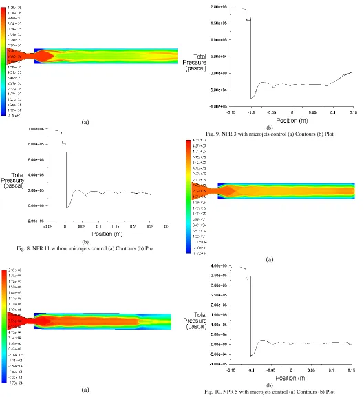
B. Pressure Flow
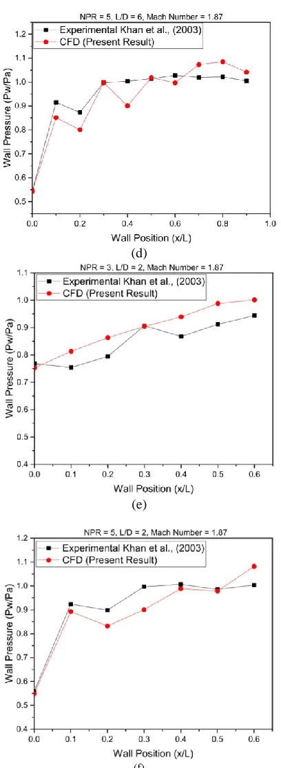
Fig. 3 to 7 illustrate the pressure flow from the inlet to the outlet without control. In this case, the optimized pressure is in Pascal and wall is considered from the inlet to the outlet of the C-D nozzle. Fig. 4 to 8 show the wall pressure plot and contour which indicate that the pressure variation has a sudden change when the level of expansion NPR increases. Also, it is
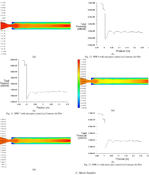
seen that the length of the recirculation zone at the corner of the C-D nozzle is high which results in low pressure at the base area and gives more drag. Therefore, to control base flow and hence reduce the base drag in sudden expansion region we have placed the microjets which will break the vortex at the base, and that will result in manipulation of the recirculation zone. This process will increase the base pressure and will also result in forwarding movement of the reattachment point of the flow which as shown in fig. 9 to 13. When micro jets employed at the base region of the sudden expansion the wall pressure with and without the control remains the same. Moreover, for NPR 3 the microjets behave differently due to the low-pressure inlet and the jets are highly over expanded. With further increase in the NPR, the level of overexpansion will go down, and the control effectiveness will improve.
(a)
(b)
(a)
(b)
Fig. 5. NPR 5 without microjets control (a) Contours (b) Plot
(a)
(b)
Fig. 6. NPR 7 without microjets control (a) Contours (b) Plot
(a)
(b)
(a)
(b)
Fig. 8. NPR 11 without microjets control (a) Contours (b) Plot
(a)
(b)
Fig. 9. NPR 3 with microjets control (a) Contours (b) Plot
(a)
(b)
(a)
(b)
Fig. 11. NPR 7 with microjets control (a) Contours (b) Plot
(a)
(b)
Fig. 12. NPR 9 with microjets control (a) Contours (b) Plot
(a)
(b)
Fig. 13. NPR 11 with micro jets control (a) Contours (b) Plot
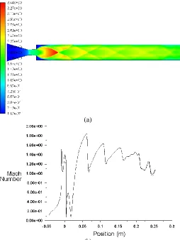
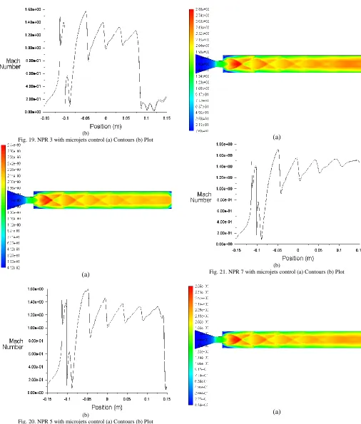
C. Mach Number
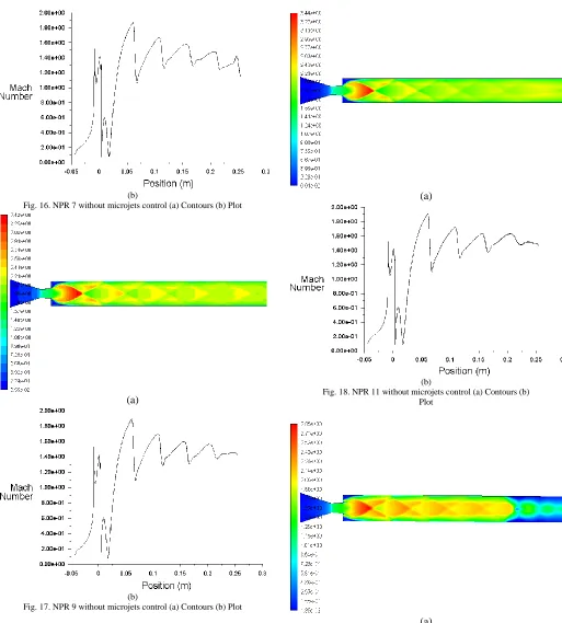
number. Fig. 14 to 18 shows the Mach number variation without micro jets control. The contours and plots have been considered to optimize the flow variables. From the Figs. 13 to 17, show the recirculation is very high at the base corner. Moreover, to control this enhanced recirculation zone the microjets becomes active, and suction becomes very low this means that the control has resulted in a decrease of the drag and the downward direction in the downstream the flow at the exit of the nozzle which may result in increases the Mach Number which is shown in fig. 19 to 23. For low-pressure variation, the Mach number varies differently, and at the exit of the nozzle, the value of the Mach number is low for other cases the value will become high.
(a)
(b)
Fig. 14. NPR 3 without microjets control (a) Contours (b) Plot
(a)
(b)
Fig. 15. NPR 5 without microjets control (a) Contours (b) Plot
(b)
Fig. 16. NPR 7 without microjets control (a) Contours (b) Plot
(a)
(b)
Fig. 17. NPR 9 without microjets control (a) Contours (b) Plot
(a)
(b)
Fig. 18. NPR 11 without microjets control (a) Contours (b) Plot
(b)
Fig. 19. NPR 3 with microjets control (a) Contours (b) Plot
(a)
(b)
Fig. 20. NPR 5 with microjets control (a) Contours (b) Plot
(a)
(b)
Fig. 21. NPR 7 with microjets control (a) Contours (b) Plot
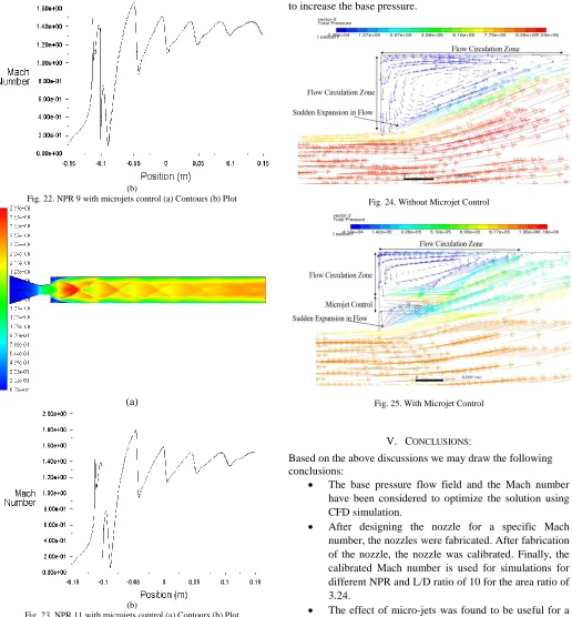
(b)
Fig. 22. NPR 9 with microjets control (a) Contours (b) Plot
(a)
(b)
Fig. 23. NPR 11 with microjets control (a) Contours (b) Plot
D. Flow Circulation at Base Region
Figs. 24 to 25 indicate the flow field in the re-circulation zone with and without control. In the absence of control, there is a re-circulation zone seen creating a low-pressure region. However, when the control is employed at the base, it can
Fig. 24. Without Microjet Control
Fig. 25. With Microjet Control
V. CONCLUSIONS:
Based on the above discussions we may draw the following conclusions:
The base pressure flow field and the Mach number have been considered to optimize the solution using CFD simulation.
After designing the nozzle for a specific Mach number, the nozzles were fabricated. After fabrication of the nozzle, the nozzle was calibrated. Finally, the calibrated Mach number is used for simulations for different NPR and L/D ratio of 10 for the area ratio of 3.24.
The effect of micro-jets was found to be useful for a given level of expansion and a fixed level of inertia. From the above results, it is concluded that total
pressure varying from the inlet to the outlet and value of total pressure is high for NPR 11.
pressure is low by considering the total wall pressure flow and velocity is high by monitoring the Mach number at the exit.
Results indicate the flow field in the re-circulation zone with and without control. In the absence of control, there is a recirculation zone seen creating a low-pressure region. However, when the control is employed at the base, it can break the dominant vortex present in the base region and able to increase the base pressure.
The validated results obtained through simulation as well as experiments will be handy during the initial design stage of the aerospace vehicle.
REFERENCES
[1] A. Khan, A. Aabid, and S. A. Khan, “CFD analysis of convergent-divergent nozzle flow and base pressure control using micro-JETS,”
International Journal of Engineering and Technology, vol. 7, no. 3.29, pp. 232–235, 2018.
[2] S. A. Khan and A. Aabid, “CFD Analysis of CD Nozzle and Effect of Nozzle Pressure Ratio on Pressure and Velocity For Suddenly Expanded Flows,” International Journal of Mechanical and Production Engineering Research and Development, vol. 8, no. June, pp. 1147–1158, 2018.
[3] A. G. M. Fharukh, A. A. Alrobaian, A. Aabid, and S. A. Khan, “Numerical Analysis of Convergent-Divergent Nozzle Using Finite Element Method,” International Journal of Mechanical and Production Engineering Research and Development, vol. 8, no. 6, pp. 373–382, 2018.
[4] G. M. Kumar, D. X. Fernando, and R. M. Kumar, “Design and Optimization of De Laval Nozzle to Prevent Shock-Induced Flow Separation,” vol. 3, no. 2, pp. 119–124, 2013.
[5] Karna S. Patel, “Flow analysis and optimization of supersonic rocket engine nozzle at a various divergent angle using Computational Fluid Dynamics (CFD),” IOSR Journal of Mechanical and Civil Engineering (IOSR-JMCE), vol. 11, no. 6, pp. 1–10, 2014.
[6] N. D. Deshpande, S. S. Vidwans, P. R. Mahale, R. S. Joshi, and K. R. Jagtap, “theoretical and CFD Analysis of De-Laval Nozzle,”
International Journal of Mechanical And Production Engineering, vol. 2, no. 4, pp. 2320–2092, 2014.
[7] O. J. Shariatzadeh, A. Abrishamkar, and A. J. Jafari, “Computational Modeling of a Typical Supersonic Converging-Diverging Nozzle and Validation by Real Measured Data,” Journal of Clean Energy Technologies, vol. 3, no. 3, pp. 220–225, 2015.
[8] O. Kostic, Z. Stefanovic, and I. Kostic, “CFD modeling of supersonic airflow generated by a 2D nozzle with and without an obstacle at the exit section,” FME Transaction, vol. 43, no. 2, pp. 107–113, 2015.
[9] K. A. Pathan, S. A. Khan, and P. S. Dabeer, “CFD Analysis of Effect of Area Ratio on Suddenly Expanded Flows,” in 2nd International Conference for Convergence in Technology (I2CT) CFD, 2017, pp. 1192–1198.
[10] K. A. Pathan, S. A. Khan, and P. S. Dabeer, “CFD Analysis of Effect of Mach number, Area Ratio, and Nozzle Pressure Ratio on Velocity for Suddenly Expanded Flows,” in 2nd International Conference for Convergence in Technology (I2CT) CFD, 2017, pp. 1104–1110.
[11] K. A. Pathan, S. A. Khan, and P. S. Dabeer, “CFD Analysis of Effect of Flow and Geometry Parameters on Thrust Force Created by Flow from Nozzle,” in 2nd International Conference for Convergence in Technology (I2CT) CFD, 2017, pp. 1121–1125. [12] K. A. Pathan, P. S. Dabeer, and S. A. Khan, “An Investigation to
Control Base Pressure in Suddenly Expanded Flows,” International Review of Aerospace Engineering (IREASE), vol. 11, no. August, pp. 162–169, 2018.
[13] K. A. Pathan, P. S. Dabeer, and S. A. Khan, “Optimization of Area Ratio and Thrust in Suddenly Expanded Flow at Supersonic Mach Numbers,” Case Studies in Thermal Engineering, 2018.
[14] S. A. Khan, M. A. Fatepurwala, K. N. Pathan, P. S. Dabeer, and M. A. A. Baig, “CFD Analysis of Human Powered Submarine to Minimize Drag,” International Journal of Mechanical and Production Engineering Research and Development, vol. 8, no. 3, pp. 1057–1066, 2018.
[15] D. S. Sahana and A. Aabid, “CFD Analysis of Box Wing Configuration,” International Journal of Science and Research (IJSR), vol. 5, no. 4, pp. 706–709, 2016.
[16] G. M. Fharukh Ahmed, M. A. Ullah, and S. A. Khan, “Experimental study of suddenly expanded flow from correctly expanded nozzles,”
ARPN Journal of Engineering and Applied Sciences, vol. 11, no. 16, pp. 10041–10047, 2016.
[17] J. D. Quadros, S. A. Khan, and A. A. J., “Modelling of Suddenly Expanded Flow Process in Supersonic Mach Regime using Design of Experiments and Response Surface Methodology,” Journal of Computational Applied Mechanics, vol. 49, no. 1, pp. 149–160, 2018.
[18] V. Kumar and F. S. Alvi, “Toward Understanding and Optimizing Separation Control Using Microjets,” AIAA Journal, vol. 47, no. 11, pp. 2544–2557, 2009.
[19] P. Kreth, F. Alvi, V. Kumar, and R. Kumar, “Microjet based active flow control on a fixed-wing UAV,” in 48th AIAA Aerospace Sciences Meeting Including the New Horizons Forum and Aerospace Exposition, 2010.
[20] Z. I. Chaudhary, V. B. Shinde, M. Bashir, and S. A. Khan, “Experimental Investigation on the Effectiveness of Active Control Mechanism on Base Pressure at Low Supersonic Mach Numbers,” in
Innovative Design & Development Practices in Aerospace and Automobile Engineering, Lecture Notes in Mechanical Engineering, 2016, pp. 195–207.
[21] S. A. Khan and E. Rathakrishnan, “Active Control of Suddenly Expanded Flows from Underexpanded Nozzles Dividing streamline Expansion waves Shock Reattachment point Recirculation,”
International Journal of Turbo and Jet Engines, vol. 3, no. 21, pp. 233–254, 2004.
[22] S. A. Khan and E. Rathakrishnan, “Control of Suddenly Expanded Flow from Correctly Expanded Nozzles,” International Journal of Turbo and Jet Engines, vol. 21, no. 4, pp. 255–278, 2008.
[23] S. A. Khan and E. Rathakrishnan, “Control of suddenly expanded flow,” Aircraft Engineering and Aerospace Technology: An International Journal, vol. 78, no. 4, pp. 293–309, 2006.
[24] S. A. Khan and E. Rathakrishnan, “Active Control of Base Pressure in Supersonic Regime,” Journal of Aerospace Engineering, Institution of Engineers, India, vol. 87, pp. 1–8, 2006.
[25] S. A. Khan and E. Rathakrishnan, “Reattachment Point Recirculation,” International Journal of Turbo and Jet Engines, vol. 23, pp. 233–257, 2006.
[26] S. Rehman and S. A. Khan, “Control of base pressure with micro-jets: Part I,” Aircraft Engineering and Aerospace Technology, vol. 80, no. 2, pp. 158–164, 2008.
[27] M. A. A. Baig, S. A. Khan, C. Ahmed Saleel, and E. Rathakrishnan, “Control of base flows with microjet for an area ratio of 6.25,”
ARPN Journal of Engineering and Applied Sciences, vol. 7, no. 8, pp. 992–1002, 2012.
[28] S. Ashfaq, S. A. Khan, and E. Rathakrishnan, “Control of Base Pressure with Micro Jets for Area Ratio 2.4,” International Review of Mechanical Engineering, vol. 8, no. 1, pp. 1–10, 2014.
[29] Z. I. Chaudhary, V. B. Shinde, M. Bashir, and S. A. Khan, “Experimental Studies of the Base Flow from the Nozzles with Sudden Expansion with Micro Jets,” International Journal of Energy, Environment, and Economics published by NOVA Science Publishers, vol. 24, no. 1, pp. 59–66, 2016.
[30] K. M. Pandey and V. Kumar, “CFD Analysis of Four Jet Flow at Mach 1. 74 with Fluent Software,” International Journal of Chemical Engineering and Applications, vol. 1, no. 4, pp. 302–308, 2010.
2016, no. 3, pp. 184–191.
[34] Z. I. Chaudhary, V. B. Shinde, and S. A. Khan, “Investigation of base flow for an axisymmetric suddenly expanded nozzle with micro JET,” International Journal of Engineering & Technology, vol. 7, pp. 236–242, 2018.
[35] S. A. Khan, Z. I. Chaudhary, and V. B. Shinde, “Base Pressure Control by Supersonic Micro Jets in a Suddenly Expanded Nozzle,”
International Journal of Mechanical & Mechatronics Engineering IJMME-IJENS, vol. 18, no. 04, pp. 101–112, 2018.
[36] E. Of, S. Expansion, F. O. R. Varied, A. Ratios, and S. F. Regimes, “Effect of sudden expansion for varied area ratios at subsonic and sonic flow regimes,” in Proceedings of ISET2016 International Conference on Energy Systems and Developments, 2016, pp. 261– 268.
[37] A. Saleel, M. A. A. Baig, and S. A. Khan, “Experimental Investigation of the Base Flow and Base Pressure of Sudden Expansion Nozzle Experimental Investigation of the Base Flow and Base Pressure of Sudden Expansion Nozzle,” IOP Conference Series: Materials Science and Engineering, 2018.
[38] Z. I. Chaudhary, V. B. Shinde, M. Bashir, and S. A. Khan, “Experimental Investigation on the Effectiveness of Active Control Mechanism on Base Pressure at Low Supersonic Mach Numbers,” in
In Innovative Design and Development Practices in Aerospace and Automotive Engineering, 2017, pp. 197–209.
[39] J. D. Quadros, S. A. Khan, and Antony A. J., “Investigation of the effect of process parameters on suddenly Expanded flows through an axi-symmetric nozzle for different Mach Numbers using Design of Experiments,” in IOP Publishing House, IOP Conf. Series: Materials Science and Engineering, 2017, pp. 1–8.
[40] M. Asadullah, S. A. Khan, W. Asrar, and E. Sulaeman, “Low-Cost Base Drag Reduction Technique,” International Journal of Mechanical Engineering and Robotics Research, vol. 7, no. 4, pp. 428–432, 2018.
[41] J. D. Quadros, S. A. Khan, and A. J. Antony, “Effect of Flow Parameters on Base Pressure in a Suddenly Expanded Duct at Supersonic Mach number Regimes using CFD and Design of Experiments,” Journal of Applied Fluid Mechanics, vol. x, no. x, 2016.
[42] P. Viswanath, “Flow management techniques for base and afterbody drag reduction,” Progress in Aerospace Sciences, vol. 32, no. 2–3, pp. 79–129, 1996.
[43] M. Badrinarayanan, “An experimental investigation of base flows at supersonic speeds,” Journal of the Royal Aeronautical Society, vol. 65, no. 607, pp. 475–482, 1961.
[44] A. Saleel, M. A. Ali Baig, and S. A. Khan, “Experimental Investigation of the Base Flow and Base Pressure of Sudden Expansion Nozzle,” IOP Conference Series: Materials Science and Engineering, vol. 370, p. 012052, 2018.
[45] J. D. Quadros, S. A. Khan, and A. J. Antony, “Study of Effect of Flow Parameters on Base Pressure in a Suddenly Expanded Duct at Supersonic Mach Number Regimes using CFD and Design of Experiments,” Journal of Applied Fluid Mechanics, vol. 11, no. 2, pp. 483–496, 2018.
[46] P. Viswanath and S. Patil, “Effectiveness of passive devices for axisymmetric base drag reduction at Mach 2,” Journal of Spacecraft and Rockets, vol. 27, no. 3, pp. 234–237, 1990.
[47] J. D. Quadros, S. A. Khan, A. A. J., and J. S. Vas, “Experimental and Numerical Studies on Flow From Axisymmetric Nozzles Flow With Sudden Expansion For Mach 3.0 Using CFD,” in International Journal of Energy, Environment, and Economics published by NOVA Science Publishers, 2016, vol. 24, no. 1, pp. 87–97. [48] Z. I. Chaudhary, “Experimental Studies of the Base Flow From the
Nozzles,” in Proceedings of ISET2016 International Conference on
[51] J. D. Quadros, S. A. Khan, and A. J. Antony, “Control of Suddenly Expanded Flows : A Taguchi Approach.”
[52] M. Asadullah and S. A. Khan, “Control of Base Pressure with Variable Location of Clockwise Rotating Cylinder,” International Conference on Advances in Thermal Systems, Materials and Design Engineering, pp. 1–7, 2017.
[53] A. Jalaluddeen, M. Ahmed, and A. L. I. Baig, “Passive Control of Base Drag in Compressible,” vol. 8, no. 4, pp. 39–44, 2018. [54] M. Asadullah and S. A. Khan, “Position of Static Cylinder Effect on
Base Flows.”
[55] M. Asadullah, S. A. Khan, W. Asrar, and E. Sulaeman, “Active control of base pressure with the counter-clockwise rotating cylinder at Mach 2,” 2017 4th IEEE International Conference on Engineering Technologies and Applied Sciences (ICETAS), pp. 1–6, 2017.
[56] M. Asadullah, “A new approach to the low-cost open-typed subsonic compressible flow wind tunnel for academic purpose,” International Journal of Mechanical and Production Engineering Research and Development, vol. 8, no. 6, pp. 383–394, 2018.
[57] M. Asadullah, S. A. Khan, W. Asrar, and E. Sulaeman, “Low-Cost Base Drag Reduction Technique,” 2018.
[58] S. Poh, A. Baz, and B. Balachandran, “Counter Clockwise Rotation of Cylinder with Variable Position to Control Base Flows Counter Clockwise Rotation of Cylinder with Variable Position to Control Base Flows Mach number,” IOP Conference Series: Materials Science and Engineering, 2018.
[59] M. Asadullah, S. A. Khan, W. Asrar, and E. Sulaeman, “Passive control of base pressure with static cylinder at supersonic flow,” in
IOP Publishing House, IOP Conf. Series: Materials Science and Engineering, 2018, pp. 1–10.
[60] S. A. Khan, M. Asadullah, and J. Sadhiq, “Passive Control of Base Drag Employing Dimple in Subsonic Suddenly Expanded Flow,”
International Journal of Mechanical & Mechatronics Engineering, vol. 8, no. 03, pp. 69–74, 2018.
[61] M. Asadullah, S. A. Khan, W. Asrar, and E. Sulaeman, “Counter Clockwise Rotation of Cylinder with Variable Position to Control Base Flows,” IOP Conference Series: Materials Science and Engineering, vol. 370, p. 012058, 2018.
[62] ANSYS Inc, “ANSYS FLUENT 18.0: Theory Guidance,” Canonsburg PA, 2017.