http://www.sciencepublishinggroup.com/j/ijepe doi: 10.11648/j.ijepe.20170604.13
ISSN: 2326-957X (Print); ISSN: 2326-960X (Online)
Experimental Testing of a Serpentine Flat Plate Solar Water
Heater
Gutu Birhanu Oliy
1, Auch Venkata Ramayya
21
Rural Energy Engineering Research Team Bako Agricultural Engineering Resarch Center, Oromia Agricultural Research Institute, Oromia, Ethiopia
2
School of Mechanical Engineering, Institute of Technology, Jimma University, Oromia, Ethiopia
Email address:
gtbr2006@gmail.com (G. B. Oliy), venkata9999@yahoo.com (A. V. Ramayya)
To cite this article:
Gutu Birhanu Oliy, Auch Venkata Ramayya. Experimental Testing of a Serpentine Flat Plate Solar Water Heater. International Journal of Energy and Power Engineering. Vol. 6, No. 4, 2017, pp. 61-67. doi: 10.11648/j.ijepe.20170604.13
Received: May 17, 2017; Accepted: May 25, 2017; Published: August 18, 2017
Abstract:
The aim of the study is to improve thermal performance of passive serpentine flat plate solar collectors using striped technique. Striped mechanism was applied on absorber plate so as to diminish thermal fusion in the plate and investigation enhancing practice of energy conversion from the collector units to the working fluid. Study was conducted or carried out using experimental testing. Demand of domestic hot water has mostly been filling with conventional flat plate solar collectors. Conventional solar collectors are relevant for high flow rate that requires high operational costs. In the past, serpentine solar collector was ignored due to large pumping requirements at higher flow rates. However at low flow rate, serpentine collector is more economical and efficient. Therefore, striped absorber plate of the serpentine solar collector in varoius modes were designed by Solid Work and CATIA. The effect of the configuration parameters of striped serpentine solar collector was investigated and good result was obtained. The analysis was done by decoupling the last striped from whole system. So that the result of the second stripe became inlet boundary condition for the last of four segments. For the collector mass flow rate of 0.00285kg/s and solar radiation of 650w/m2, temperature of absorber plate and water at collector exit became 353k and 336.9k respectively.Keywords:
Thermal Breaking, Serpentine Solar Collector, Thermosyphone & Experiment1. Introduction
Solar collectors are special kind of a device that transform solar irradiance into internal energy of the transport medium, and hence increases their thermal effects. They absorb and capture the incoming solar radiation, convert it into heat and transfers the heat to a fluid flowing through the collector [1]. Previousely demand of domestic hot water has been satisfying with other energy source than solar. However, solar water heating alone can reduce domestic water heating costs by as much as 70% [2]. Flat-plate solar collector is the most common for residential water and space heating as well as for industrial application. Most of the flat plate collectors currently available on the market are of the parallel tube type known as conventional flat plate solar collector [3]. They are relevants for high flow rate that requires high operational costs. Moreover,
conventional flat plate collector had been in service for a long time without any significant changes in their design, shape and operational principles [4].
According to Matrawy & Farkas [5] configuration of a solar collector is an important factor that determines its thermal performance. Serpentine solar collector has the potential to perform better than a conventional parallel tube collector in low-flow systems due to the earlier onset of turbulent flow which enhances heat transfer application. Even for the same collector area, tube spacing and tube diameter, serpentine collector performer better than conventional collector [6]. According to Myrna & Beckman [7] the major reason for the difference in performance between conventional and a serpentine flat plate solar collector was the internal heat transfer coefficient. However in the past, serpentine flat plate solar collector was ignored due to large pumping requirements at higher flow rates.
efficiency factor and heat removal factor cannot easily be expressed in a simple form. If thermal break is made midway between the serpentine tubes, then the collector can be analyzed as a conventional collector. If the break is not provided, reduced performance can be expected and more complicated analysis is necessary [8]. The heat removal factor for a serpentine collector is much more difficult to determine than for a conventional flat-plate collector [7]. Unlike analysis for conventional collector, there is heat transfer between the tubes for a serpentine collector.
Several paper with analytical solutions were published. All analytical solutions were done to treat the differential equations that governing the heat transfer in a serpentine-tube absorber. Abdel-Khalik [9] found an analytical solution for heat removal factor of a serpentine tube bonded to the plate with two segments. He concluded that analytical solution for two segments was applicable for any number of segments with small error. Later, Zhang and Lavan [10] showed the conclusion led to much errors for N=3 and 4. In addition ignores heat transfer application through U-bend portion and assumes one-dimensional heat transfer in the absorber plate.
Chiou & Perera [11] also analyzed the serpentine collector for any number of turns. As the number of turns increases, value of heat removal factor (FR) approach the values for turn N=1. In this case, the analysis for a long straight collector with no turns will hold. Therefore, the model is very close to the model for the flat plate collector, with the exception being that the internal heat transfer coefficient will be different [6].
So far, there are only a few publications that report on experimental results of serpentine-flow solar collector. Eisenmann & Wiese [12] had conducted experiment on two serpentine collectors that have the same geometry and shape. In the first collector, serpentine tube was soldered to the absorber plate all through the collector, whereas in the second collector bends of the tubing was not thermally connected with the absorber. They put both over the sun under identical meteorological conditions and measured their performance. The efficiency of the collector that was soldered to absorber plate became about 2 to 2.5% superior in the experiment.
The experiment was conducted on the collector whose absorber plate was soldered to serpentine tube rather than striped plate that attached to tube. In fine and tube absorber collector arrangement, heat is normally transferred through absorber plate to tubes and then working fluids. As result, thermal diffusion due conduction mode caused throughout the system which reduces overall performance in the collector. Moreover, the experiment was unable to make predictions on the required parameters UL & F’ of a serpentine-flow collector experimentally. Unlike parallel flat plate collector, there is heat transfer occur between tubes for a serpentine collector resulting in two dimensional heat transfer problem. Thus, it requires thermal break midway between serpentine tubes, and then the collector can be analyzed as a conventional collector. Consequently,
coarser approximations need to be made in order to achieve analytical solutions for the absorber and fluid temperatures (Lund, 1989) [13] as cited by [12]. Thus, it was designed to perform simulation and experimental testing of serpentine flat plate solar collector.
2. Material and Methodology
Geometry model was designed using CATIA. For better thermal and flow analysis, thermal breaking system was used. The designed model was prepared as per required, manufactured and assembled were done for the experimental test. Thermocouple sensors were provide on serpentine tube and the plate in order to gauge thermal and flow distribution through the collector. Collector site orientation was adjusted and temperature distribution through the plate as well as water in the tube recited with digital multi-meter reader.
2.1. Development of Geometry
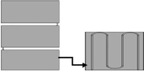
Basic serpentine flat plate solar water heater was developed and going to be investigated. Unlike conventional collector, there is a complicated heat transfer network present in between serpentine tubes in the collector which results the analysis into 2-D heat transfer problem. Therefore, it is not easy to do the analysis of flow and thermal character inside the tubes and absorber plate.
Thus, it requires appropriate thermal breaking application in the system. Breaking in the midway was one of the option but using more breaking system cause further complication on the setup of the boundary condition for decoupling and/or coupling system.
Figure 1. Striped geometry get decoupled from main system as this.
2.2. Prototype Manufacturing
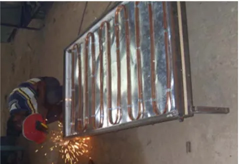
Similar model of serpentine solar collector was manufactured with striped techniques where the plate was attached to serpentine shaped tube for separated segments. Striped mechanism prohibited or minimizes intensity of thermal losses through the collector active part without doing the required work. Thermocouple sensor was provide on serpentine tube and the plate in order to gauge thermal and flow distribution through the collector.
between two adjacent plates with about 20mm part. That thermal line was covered with Styrofoam material which serve as insulator for heat to minimize air circulation in the collector.
Figure 2. Physical feature, how serpentine tube bend to required shape & kept in collector system.
Since the collector rely on natural circulation system, significant amount of heat can be gained due to unique property of low flow rate.
2.3. Experimental Setup
Experiment setup was established in Jimma Agricultural Mechanization Research Center Lab and testing was conducted for over one month with outdoor condition. The collector was designed with two thermal breaking lines that divided the collector into three striped real model.
And all the collector units were kept over the sun to trap incident radiation. Serpentine tube was soldered to the absorber plate to enhance thermal flow in favor of contact with aluminum sheet that has 0.8mm thickness. They are used to establish good heat transfer application between absorber plate and the tube and also insist heat transfer process from plate to transport fluid.
2.4. Collector Orientation
The collector position was adjusted to best performing angle of orientation. This should be as close as possible to Due South (0°) in the Northern Hemisphere for absorption of maximum solar irradiation. The surface orientation leading to maximum output of a solar energy system may be quite different from the orientation leading to maximum incident energy. The total annual energy received as a function of slope is maximum at approximately β = ∅ where ∅ is the latitude. For maximum annual energy availability, a collector tilt angle equal to the latitude is considered [8].
The performance of the solar water heater depends on prompt exposure to incoming solar radiation. Therefore, the solar collector should be far from block obstacles like tall buildings, trees or hills positioned in front and back side that hindered them to gain substantial solar energy.
Table 1. Collector Specification.
Symbol Parameter Magnitude
L Length of one serpentine segment 0.96m W Distance b/n tubes 0.14m δ Plate thickness 0.8mm D Tube outside diameter 12.7mm Di Tube inside diameter 11.28mm k Plate thermal conductivity 46 w/m °C
mɺ Mass flow rate of water 0.0028kg/s Ac Collector area 1.52m2
β Collector slope angle 10° - Space b/n plate & glass 20mm Lb Thickness of back insulation 0.046m
Kb Back insulation thermal conductivity 0.02w/m °C
- Thickness of collector 0.085m
3. Result and Discussion
3.1. Introduction
Temperature distributions inside flow tube and absorber plate of serpentine collector were predicted thereby to estimate collector efficiency factor and other parameters that express collector performance. Here flow characteristics and thermal performance of the serpentine solar collector was examined by experimental testing.
Temperature distribution through the plate and working fluid has been followed with K-type thermocouple sensors. The sensor displayed the input in the form of voltage and the voltage was translated in to temperature using standard table. Eventually, the result obtained with computational fluid dynamics simulation analysis was compared with experimental testing outcome for validation purpose.
3.2. Collector Properties
The properties of water were temperature-dependent and piecewise-linear functions were used to take into account dependence of water properties upon its temperature. On top surface of absorber plate, equivalent heat fluxes of 650W/m2 was applied. Providing that the side and the bottom part of the plate was set to be at adiabatic condition.
Because of the serpentine solar collectors was set to be inclined to horizontal, the effect of gravity was taken into account along the vertical axis by specifying the negative acceleration value of cosine 10° multiplied by the gravitational forces constant [16]. Collector angle was established based on recommendation made with literature. Experimental site has latitude of 7.7° and collector angle was made to be 100 for best annual solar radiation collection option without applying tracking system.
3.3. Leak Test Result
The smallest bubble an operator could detect has 1 mm radius and that the waiting time is 30 seconds [17]. Assuming that the pressure inside the bubble is at atmospheric pressure, it can be stated from the previous equations that the bubble volume is ϑ=4.2*10-3 cm3 and therefore the minimum detectable leak rate at Jimma atmospheric condition become 1.2*10-4 mbar*l/s.
3.4. Estimation of Solar Radiation
The thermal performance of natural circulation solar water heating was tested on June 30, 2014 at Jimma Agricultural Mechanization Research Center using serpentine flat plate solar collector setup with batch type water tank. An estimation of solar insolation of that experimental site was made by employing engineering equation solver (EES) software. A program that compromised important parameters of air with non-dimensional units was developed. Data’s were collected on the temperature of air, sky and black body with ten minute intervals. Since once the program was developed, the collected data was inserted in the program and manipulated.
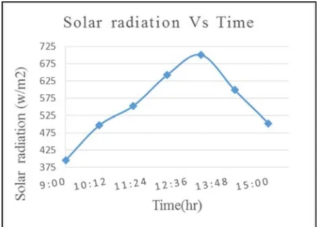
Figure 3 shows the profile of solar radiation available that was calculated based on data of the test day. Since season was summer, it has been difficult to get a clear day to do performance test and several trials have been done to get good daily solar curve. This data was one of the best clear days for performance test.
Figure 3. Solar radiation on June 30, 2014 at Jimma Agricultural Mechanization Research Center.
Due to decreases in solar radiation, the ambient temperature also starts to decrease. Ambient temperature variation of the experimental site also has the following pattern.
Figure 4. Ambient temperature variation of the experimental site.
3.5. Experiment Result
Temperature distribution through the plate and water in the tube were measured using k-type thermocouple. Since the thermal breaking system was applied, absorber plate was detached from each other and fixed to tube with soldering techniques. On the serpentine tube, this temperature sensors were attached on holes so as to read temperature distribution through the flow. In addition, the sensor was attached on the surface of plate to measure how hot could absorber surface be.
Table 2 below displays temperature of water flow in the serpentine tube. The collector system was divided into three stripes as result of thermal breaking application and on each strip as per the thermocouple sensor allocated, data has been registered with in 20 minute intervals. Different reading of temperature was recorded at every hour and average values of water temperature are considered. Here temperature was read in terms of voltage induced caused due to temperature difference between conducting wires in sensor. Using this induced voltage, corresponding temperature was read using standard table including ambient temperature.
Table 2. Temperature of water in the tube at various points.
Z (m) 0.09 0.16 0.30 0.42 0.56 0.83 0.97 1.12 1.26 1.48 1.47 1.52 X (m) - 0.48 0.93 0.03 0.93 0.48 0.03 0.48 0.93 0.48 0.03 0.93 Tw (K) 295 298.2 302.5 317.4 317.6 319.3 320.7 322.9 323.3 323.5 336.9 317.4
Table 3 displayed average plate temperature distribution in the absorber plate. Temperature of the plate was computed on average based and displayed here at every ends of the strips. Four temperature values were shown as per the stripes.
Table 3. Absorber plate temperature at various points.
Z-axis (m) 0.295 0.68 1.15 1.55
X-axis (m) 0.45 0.57 0.35 0.48
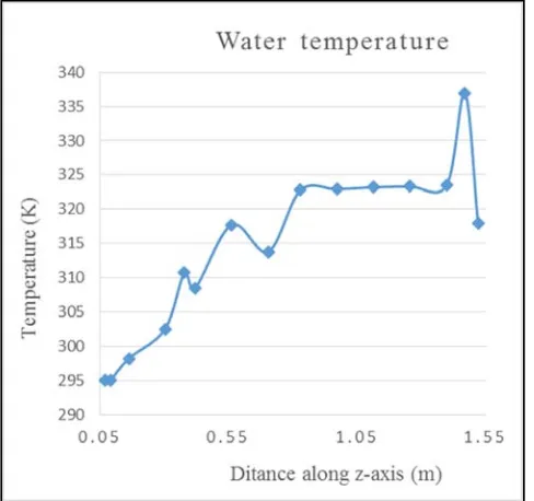
Figure 5 indicated that how temperature of the flow was varied with location. This figure displays temperature distribution of water flow in tube along z-axis. Water was admitted to inlet of the collector at temperature of 20°C. As it passes through the tube, heat transfer takes place so that water start gaining considerable heat from the process. As it can be seen from the graph, the water in the tube extract little amount of heat in first strip since it goes short distance to complete loop.
Figure 5. Temperature variation of water in the collector.
In the above diagram, the maximum temperature of the water in the first strip was 310k but as it passed to the next strip, considerable amount of heat was enabled to be gained. Due to possibility of long contact time with the tube surface that causes good heat transfer process in the system. As result, water in the tube gained significant amount of heat. The water in the tube attained maximum temperature of 337k throughout the system.
Figure 6 displayed below demonstrated collector plate temperature distribution in whole strips. Temperature variation is taken in average based at each end of the strips. In second and third strips, collector plate temperature was sharply increasing and attain maximum temperature of 351k at the middle third strips. Here solar radiation directly fallen on the absorber plate and there was no apparent shading effect.
For last strips, there is possibility of self-shading effect for time before noon. Even though water storage tank was suited above the collector, it affected thermal performance of the last strip. The graph is drawn using result obtained at 14hr.
Figure 6. Temperature distribution in absorber plate.
Table 4 below has displayed the summary of water of temperature at tube exit obtained by CFD simulation and experimental testing. The data’s were kept here to comparison the result obtained with both simulation and testing.
Table 4. Summary of water temperature in tube obtained by experimental testing.
Time (hr) Insolation
(w/m2) T (amb) (k)
T (water in exper) (K)
9:00 396 295 305
10:00 497.6 296 317.73 11:00 552.2 298.5 313.73 12:00 641.8 299.4 322.77 13:00 648.6 300.3 323.38 14:00 700.5 299.2 336.9 15:00 562.5 298 318.43
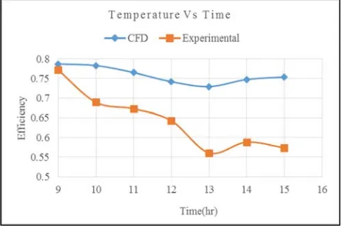
Collector instantaneous efficiency was found to vary according to the external conditions i.e. solar radiation, ambient temperature and mean tanker temperature. The efficiency curve of experimental results agreed with model. The collector system showed higher efficiency at low tank temperature and the efficiency decreases as the tank temperature increases. An average tank temperature was 322k and FRτα is the y-intercept in the efficiency line and FRUL represents the slope of the curve.
The higher the slope, the higher is the sensitivity to external conditions. Both experimental and model collector curves have high slope value which indicates the efficiency is very sensitive to external condition. The heat transfer coefficient UL also depends on the mean plate temperature.
Figure 8. Collector Instantaneous efficiency during test hours.
Khalifa [18] experimentally investigated the impact of mean plate temperature on the total and collector top heat transfer coefficient. It was found the total and collector top heat transfer coefficient varies during the test hours due to the increase solar radiation and the mean absorber temperature. Higher collector inlet temperature increases the mean plate temperature and increases the collector total heat transfer coefficient which reduces the efficiency of the collector.
4. Conclusion
Thermal performance of flat plate solar collector can be improved by altering its configuration of heat transport system from solar absorber to heat storage system. Solar collector size, shape and flow rate in general affect system performance. Serpentine flat plate collector was designed based on thermal breaking system that was recommended by different literatures. Unless thermal breaking was applied, it is difficult to model formulae that enable to analysis as conventional collector. The performance of this collector was investigated by experimental testing. Collector model was designed applying CATIA and Manufacturing of real prototype was made in our workshop.
For the collector mass flow rate of 0.00285kg/s and solar radiation of 650w/m2, temperature of absorber plate and water at collector exit during the experimental test attained
maximum temperature of 353k and 336.9k respectively. Here, data obtained with experimental investigation was agreed with numerically predicted temperature distribution on the striped absorber plates with little discrepancy. This inconsistency was due to variance of solar radiation and data measurement error. In case of collector heat removal factors, both numerical study and experimental testing was similar in figures and remarkable with other research.
Collector model had three stripes, all strips exhibited varies temperature distribution in the collector system. During experimental session, solar radiation is directly fallen on the absorber plate and there is no apparent shading effect seen especially for the time before noon in second strips whereas in third and last strips, there is possibility of self-shading effect observed for time before noon. Even though water storage tank was suited above the collector, it affected thermal performance of the last strip. Consequently, such temperature variation was happened in the last stripe.
Serpentine solar collector requires further study to model the science exist behind the collector. So far different studies were conducted on the collector to model collector’s important parameters using analytical methods for several turns. Yet modelled collector heat removal factor (FR) formula was invalid for all materials.
As it is know that serpentine solar collector has geometry for which collector efficiency factor and heat removal factor cannot easily be expressed in a simple form. Unlike the analysis for the parallel flat-plate where the fins between the tubes are assumed adiabatic at the center of the tube spacing, there is heat transfer occur between the tubes. However no analytical modelling was formulated for collector efficiency factor for serpentine solar collector. It is unable to make predictions on the thermal output of a serpentine-flow collector with experimental.
In such manner, analysis of collector system was done and finally coupled together to become the collector system. This method may works for fluid flow in the tube but might be difficult with air, cover and insulation material that were thermally broken for analysis. Therefore, more effort is required to model (F’) to analyze the thermal behavior of the tube bends. Moreover, detailed numerical investigations should also be taken into consideration.
References
[1] J Soteris A. Kalogeria, “Solar Energy Engineering Processes and Systems Book, 1st edition”, Elsevier Inc. All right is reserved, 30 Corporate Drive, Suite 2000, Burlirgto, MA 01803, USA, pp. 121-130, 2009.
[2] Mohamed Selmi, Mohammed J. Al-Khawaja, Abdulhamid Marafia, “Validation of CFD simulation for flat plate solar energy collector”, Renewable Energy 33, pp. 383–387, 2008.
[4] P. Sivakumar, W. Christraj, M. Sridharan and N. Jayamalathi, Performance improvement study of solar water heating system, ARPN Journal of Engineering and Applied Sciences,
Vol. 7, No 1, pp 45-49, 2012.
[5] Matrawy, K. K., Farkas, I., Comparison study for three types of solar collector for water heating. Energy Conversion and Management 38, pp. 861–869, 1997.
[6] Dayan Myrna, "High performance in low-flow solar domestic hot water systems”, MSc thesis, Dept. of Mechanical Eng., Wisconsin-Madison Univ., 1997. (Thesis).
[7] Myrna D., Sanford K. & William Beckman, “Analysis of serpentine collectors in low flow systems”, Solar Energy Laboratory University of Wisconsin-Madison 1500 Engineering Drive Madison, WI 53706, 1998.
[8] John A. Duffie & William A. Beckman, Solar Engineering of Thermal Processes, 3rd edition, Wiley-Inter science Publication John Wiley & Sons, New York, 2006.
[9] Abdel-Khalik S. I., “Heat removal factor for a flat-plate solar collector with a serpentine tube”, Journal of Solar Energy, Vol 18, pp 59-64, 1976.
[10] Zhang H.-F. & Lavan Z., “Thermal performance of a serpentine absorber plate”, Journal of Solar Energy, Vol. 34, pp 175-177, 1985.
[11] Chiou, J. P. & Perera, D. G., “Non - Iterative Solution of Heat Transfer Equation of Fluid Flowing through a Serpentine Tube attached to a plate with radiation as a heat source”,
American Society of Mechanical Engineers-Heat Transfer Division, Vol 62, pp. 89- 96, ASME, New York, 1986.
[12] Wolfgang Eisenmann, Frank Wiese, Klaus Vajen & Hans Ackermann, “Experimental investigations of serpentine-flow flat-plate collectors”, Philipps-Universität Marburg, D-35032 Marburg, Germany, 2000.
[13] Lund K. O., “General thermal analysis of serpentine-flow flat-plate solar collector absorbers”, Solar Energy Vol. 42, pp 133-142, 1989.
[14] P. W. Ingle, A. A Pawaer, B. D. Deshmukh and K. C. Bhosale, “CFD analysis of solar flat plate collector”, International Journal of Emerging Technology Advanced Engineering, Volume 3, Issue 4, pp 337-42, 2013.
[15] ASHRAE Hand Book, HVAC applications, SI edition Supported by American Society of Heating, Refrigerating and Air-conditioning Engineers Research, 2011.
[16] IORDANOU GRIGORIS, “Flat-Plate Solar Collectors for Water Heating with Improved Heat Transfer for Application in climatic Conditions of the Mediterranean region,” PhD dissertation, School of Engineering and Computor Scence., Durham Univ., 2009.
[17] VTech Leak Detection Methods, A Comparative Study of Technologies and Techniques Short version, USA, 2005.