INTERNATIONAL JOURNAL OF PHARMACEUTICAL, CHEMICAL AND BIOLOGICAL SCIENCES
Available online atwww.ijpcbs.com
STABILITY ANALYSIS OF DRAFT TUBE SPOUTED BED USING
PRESSURE FLUCTUATION ANALYSIS
P. Deepa 1* MG. Parande1, SJ. Attar1, D. Sathiyamoorthy2 and P K. Mollick2
1Department of chemical Engg, Bharati Vidyapeeth Deemed University College of Engineering,
Pune, Maharashtra, India.
2Powder Metallurgy Division, Bhabha Atomic Research Centre, Trombay, Mumbai, India.
1. INTRODUCTION
Fluidization is the operation by which solid particles are transformed into a fluid like state through suspension in a gas or liquid. Fluidization is effective for Geldart-A and B type particles. For Geldart-D type particles, fluidization becomes difficult as it gives large exploding bubbles or severe channeling. For countering the poor quality of fluidization with uniformly coarse particles, spouted bed is seen to perform well. The performance of conventional spouted bed is seen to be improved by inserting a draft tube in place of spout region which gives way to greater flexibility in the operation, lower gas flow and pressure drop, solids of any size or nature may be treated, narrower residence time distribution, better control of solid circulation, avoids maximum spoutable bed height and a better control of solid circulation.
Draft tube in spouted bed is typically a mechanical separator between annulus and
spout. Conventional draft tubes are cylindrical in shape and placed at the centre of the bed starting from immediately above the gas inlet nozzle and can be extended up to desired heights. The gap between gas inlet nozzles to the bottom of the draft tubes is knows as draft tube clearance which is a significant parameter to control solid circulation rates and thereby heat and mass transfer. Studies on Draft Tube Spouted Bed (DTSB) in last few years report parametric effects of various draft tube configurations in DTSB hydrodynamics.1
The applications of DTSB in various fields have been reported in the literature. DTSB is used for drying different types of suspensions2,3, in flue gas desulfurization
process4, as catalytic coal gasifier to
produce H25 etc.. Dynamic models of DTSB
have been developed to study the residence time distribution of fluids in annulus6,7,8,
effect of operating conditions9 , reduction
of spouted bed drying time etc when it is used as dryer10,11, sensitivity of variables
Research Article
ABSTRACT
Spouted bed is widely used in number of industries such as food, pharmaceuticals, petrochemicals, fertilizer, waste treatment, gasification etc. Spouted bed is particularly very useful in efficient drying, coating, mixing, granulation and catalytic conversion for its unique hydrodynamics which favor good heat and mass transfer. Use of draft tube in spouted bed adds further advantage to manipulate solid circulation rates and also leads to favorable hydrodynamics. Experiments were carried out at different gas flow rates in a draft tube spouted bed using argon and nitrogen as spouting gases at various bed heights and draft tube bottom clearances. Experiments were aimed to determine the condition at which stability is achieved. Standard deviation of pressure fluctuation is obtained to determine the stable spouting velocity and draft tube bottom clearance for various draft tube size. Findings report here critical aspects to achieve higher stability in drat tube spouted beds.
like gas and particle velocities and voidages in the spout region for a draft tube spouted bed with bottom particle feed12.
Stable operation of spouted bed is always advisable to achieve homogeneous solid circulation and thereby heat and mass transfer. In conventional spouted bed the stability generally refers a bubble and slug free bed with a straight and pulsation free spout region above the inlet orifice. For the case of DTSB, achieving a straight and pulsation free spout is quite easy as it is thoroughly guided by the mechanical separator named as draft tube. However, the formation of bubbles and thereby slugging near to the bottom of the Draft Tube (DT) is sometimes unavoidable unless interior of the DTSB is properly designed. In order to design interior of a DTSB major designs parameters are diameter of the DT and the DT clearance. Over and above, the formation of slug followed by formation of bubbles significantly dependent on the particle size, particle density, static bed height, choice of spouting gas, superficial gas velocity and the cone angle of the apparatus1.
The aim of our present investigation is to find out the criteria for stable spouting in DTSB using pressure fluctuation analysis. The pressure fluctuation analysis which is believed to be a good technique to analyze various spouting zones13 is applied here to
find out stable spouting zone for DTSB. The pressure data which are collected at a frequency of 100 Hz was subjected for statistical analysis and standard deviation of the fluctuation was calculated so as to delineate stable spouting operation in DTSB. The studies were carried out for four important parameters, namely, DT diameter, DT clearance, static bed height, spouting gas velocity and the choice of spouting gas.
2. EXPERIMENTAL
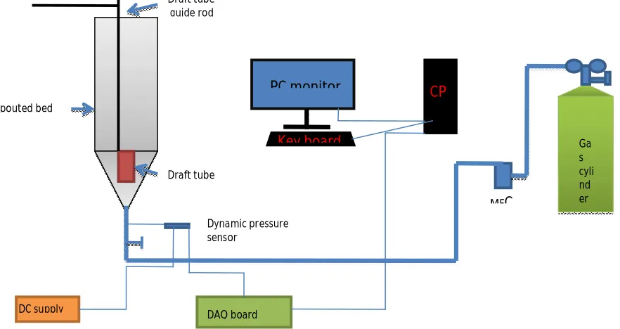
A schematic of the experimental set up is shown in figure 1. The dimensions of the spouted bed apparatus used in the experiments are provided in table 1. The spouted bed apparatus is made of transparent acrylic material to visualize spouting phenomena and particle flow in DTSB. The material of construction of the DT is polyethylene (hard) which was suspended from the top of the bed. The draft tube placement and movement were accomplished manually. Dimension of the DT is also given in table 1. Spherical zirconia microspheres of 500 m size were used as bed material and argon and nitrogen were used as spouting gases. A dynamic pressure sensor was attached about 20 mm below the gas inlet nozzle of the apparatus.
Fig. 1: Schematic of experimental set up
Ga s cyli nd er
DAQ board DC supply
PC monitor CP
U
Key board
Dynamic pressure sensor
Spouted bed
Draft tube Draft tube guide rod
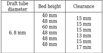
Experiments were performed as per the parameters listed in table 2. The spouting gas flow through the orifice was measured and controlled by a mass flow controller (MFC). Measured quantity of the bed material was charged from the top of the apparatus and the position of the DT was
adjusted as required. Spouting phenomena for a wide range of spouting gas velocities was studied and the pressure fluctuation data was collected at a rate of 100 Hz in each case. Pressure fluctuation data was subject to average pressure drop and standard deviation calculation.
Table 1: Dimensions of the draft tube spouted bed column
Dimension Height of the cylindrical
section Height of the conical
section Cylindrical diameter
Cone angle Diameter of inlet nozzle Diameter of draft tube (1) Diameter of draft tube (2)
Height of draft tube
400 mm 55 mm 60 mm
60o
4 mm 8 mm 8 mm 6 mm
Table 2: Experimental parameters
3. RESULTS AND DISCUSSION
Average pressure drop and the standard deviation of the pressure fluctuation were calculated from the raw data collected from the dynamic pressure sensor for all the experiments. Key findings from the experiments are reported and discussed below.
From figure 2 it can be shown that after a particular superficial gas velocity (close to U = 20 m/s), standard deviation of pressure fluctuation does not change significantly and follows the same trend for various bed heights indicating insignificant effect of bed heights on stability of draft tube spouted bed (DTSB). However before a particular gas velocity, the standard deviation appears to change dramatically and it is highly affected by bed height. It is also seen that commencement of relatively stable spouting occurs at a lower gas velocity for higher bed height and vice versa. This could be due to higher solid pressure for higher bed height which favors draft tube spouting at relatively lower gas velocity and vice versa. At the commencement of spouting,
standard deviation value is seen to be higher for bed height of 48 mm. This may be due to the maximum possible counter interaction between gas and solids at the interface between DT clearance and annulus. At lower bed height, solid pressure is low and hence standard deviation is found to be low. At higher bed height, solid pressure is high and hence standard deviation is high.
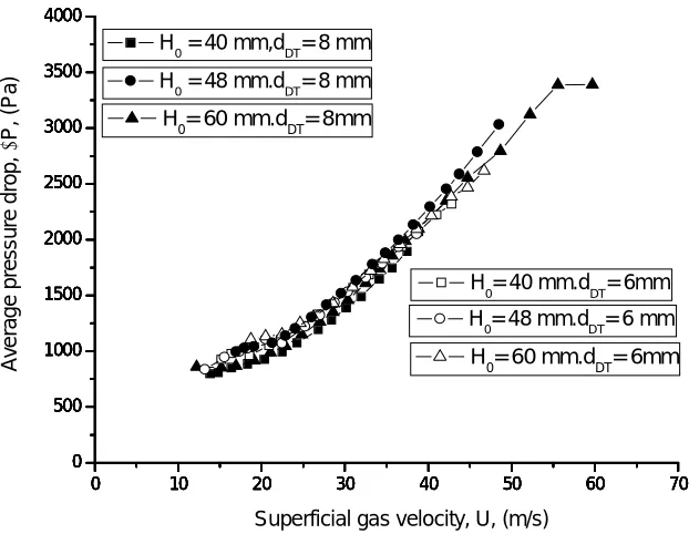
From figure 3, it can be seen that average pressure drop increases continuously with gas velocity irrespective of bed height. Until stable spouting is observed, the standard deviation of the pressure fluctuation is non-linear and it shows a linear variation at relatively higher gas velocity.
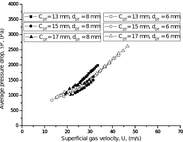
From figure 4, it is evident that draft tube clearance has a significant effect on the spouting stability. When draft tube clearance is low, the solid flow from the annulus into the draft tube is constricted. At lower gas velocity, the solid flow is further hindered. However, at higher gas velocities, the hindrance in the radial direction is less and hence spouting is smooth with high solid circulation rate. If the clearance is very high, the solid particles will fill up the area between the gas orifice and the draft tube, thereby rendering the situation akin to conventional spouted beds and hence the standard deviation of pressure fluctuation is high. The critical draft tube clearance for the experimental setup has been evaluated to be 15 mm at which the fluctuation in the pressure drop as well as the average pressure drop is less.
As can be seen in figure 5, at lower clearance, the population of the particles inside the draft tube at any instance is low resulting in the particles being pushed along the wall of the draft tube which results in an increase in the average pressure drop and vice versa.
The effect of DT diameter does not show prominent variation in average pressure drop and standard deviation as seen in figure 2-5. However, for a smaller diameter of the DT average pressure drop does not vary much for varying DT clearance. This may be due to the lower population of the particles in a smaller diameter DT which causes less pressure drop variation even if the DT clearance is changed.
Draft tube
diameter Bed height Clearance
6, 8 mm
40 mm 48 mm 60 mm 48 mm 48 mm 48 mm
0 10 20 30 40 50 60 70 0 10 20 30 40 50 60
0 10 20 30 40 50 60 70
0 10 20 30 40 50 60
0 10 20 30 40 50 60 70
0 10 20 30 40 50 60
0 5 10 15 20 25 30 35 40 45 50 55 60 65 70
0 10 20 30 40 50 60
0 10 20 30 40 50 60 70
0 10 20 30 40 50 60
0 10 20 30 40 50 60 70
0 10 20 30 40 50 60 H
0 = 40 mm, dDT = 8 mm
H
0 = 48 mm, dDT = 8 mm
H
0 = 60 mm, dDT = 8 mm
H
0 = 40 mm, dDT = 6 mm
H
0 = 48 mm, dDT = 6 mm
S ta n d a rd d e v ia ti o n o f p re s s u re f lu c tu a ti o n , (P a )
Superficial gas velocity, U, (m/s) H
0 = 60 mm, dDT = 6 mm
Fig. 2: Variation of standard deviation of pressure fluctuation with superficial gas velocity
0 10 20 30 40 50 60 70
0 500 1000 1500 2000 2500 3000 3500 4000
0 10 20 30 40 50 60 70
0 500 1000 1500 2000 2500 3000 3500 4000
0 10 20 30 40 50 60 70
0 500 1000 1500 2000 2500 3000 3500 4000
0 10 20 30 40 50 60 70
0 500 1000 1500 2000 2500 3000 3500 4000
0 10 20 30 40 50 60 70
0 500 1000 1500 2000 2500 3000 3500 4000
0 10 20 30 40 50 60 70
0 500 1000 1500 2000 2500 3000 3500 4000
H0 = 40 mm,dDT= 8 mm
A v e ra g e p re s s u re d ro p , P , (P a )
Superficial gas velocity, U, (m/s)
H0= 60 mm.dDT= 8mm
H
0= 40 mm.dDT= 6mm
H0= 48 mm.dDT= 6 mm
H0= 60 mm.dDT= 6mm
H0 = 48 mm.dDT= 8 mm
0 10 20 30 40 50 60 70 0 10 20 30 40 50 60 70
0 10 20 30 40 50 60 70
0 10 20 30 40 50 60 70
0 10 20 30 40 50 60 70
0 10 20 30 40 50 60 70
0 10 20 30 40 50 60 70
0 10 20 30 40 50 60 70
0 10 20 30 40 50 60 70
0 10 20 30 40 50 60 70
0 10 20 30 40 50 60 70
0 10 20 30 40 50 60 70 C
DT = 13 mm, dDT= 8 mm
CDT = 13 mm, dDT= 8 mm
C
DT = 13 mm, dDT= 6 mm
C
DT = 15 mm, dDT= 6 mm
CDT = 17 mm, dDT= 6 mm
S ta n d a rd d e v ia ti o n o f p re s s u re f lu c tu a ti o n , (P a )
Superficial gas velocity, U, (m/s) C
DT = 15 mm, dDT= 8 mm
Fig. 4: Variation of standard deviation of pressure fluctuation with superficial gas velocity
0 10 20 30 40 50 60 70
0 500 1000 1500 2000 2500 3000 3500 4000
0 10 20 30 40 50 60 70
0 500 1000 1500 2000 2500 3000 3500 4000
0 10 20 30 40 50 60 70
0 500 1000 1500 2000 2500 3000 3500 4000
0 10 20 30 40 50 60 70
0 500 1000 1500 2000 2500 3000 3500 4000
0 10 20 30 40 50 60 70
0 500 1000 1500 2000 2500 3000 3500 4000
0 10 20 30 40 50 60 70
0 500 1000 1500 2000 2500 3000 3500 4000
CDT= 13 mm, dDT = 8 mm
A v e ra g e p re s s u re d ro p , P , (P a )
Superficial gas velocity, U, (m/s)
CDT= 15 mm, dDT = 8 mm
CDT= 13 mm, dDT = 6 mm
CDT= 15 mm, dDT = 6 mm
CDT= 17 mm, dDT = 6 mm
CDT= 17 mm, dDT = 8 mm
4. CONCLUSION
Stability of the DTSB is successfully studied for two DT sizes and various DT clearances with different static bed heights. Stability analysis using pressure fluctuation technique for a range of gas velocity along with proper DT configuration is confirmed. Critical DT clearance is observed for stable operation of spouted bed. Present study would help in judgment of DT confirmation and DT clearance to establish a stable spouting condition in DTSB.
Nomenclature
CDT – Draft tube clearance (mm)
dDT – diameter of draft tube (mm)
DT - draft tube
DTSB – draft tube spouted bed ΔP – average pressure drop (Pa)
σ – standard deviation of pressure fluctuation (Pa)
U – Superficial gas velocity (m/s) H0 – bed height (mm).
REFERENCES
1. Epstein & Grace; Spouted and Spout-Fluid beds, Cambridge University Press, 2011.
2. Zorana Lj Arsenijevic, Zeljko B. Grbavcic and Radmila V. Garic-Grulovic; Drying of suspensions in draft tube spouted bed, Canadian journal of chemical engineering, 2004;82:450-469.
3. Phakawan Samoechai and Kanokom Photinon. Drying kinetics and reduction of spouted bed drying time of rose petals using draft tube &inert particles, Chiang Mai University Publication.
4. Yan Liu and Shao-Feng Zhang. Desulfurization characteristics in double nozzle rectangular spouted bed with draft tube; international conference on Energy and Environment Technology. 2009; 265-268.
5. Yashimitsu Uemura, Masahiko Miyauchi, Shigeho Tanaka, Kazuya Ijichi,Yasuhiko Tanaka and Desmond.F. King , Catalytic coal gasification in a draft tube spouted bed by using ceramic particles as
thermal medium, Fuel. 1972-1976. 37.
6. Seung Jai KIM. Fluid and particle flow characteristics in a draft tube spouted bed with modified fluid outlet, Korean journal of chem. Eng. 1990;7(1):74-80.
7. John H Eng, William Y Svrcek and Leo A Behie. Dynamic modeling of a spouted bed reactor with a draft tube, Ind. Eng. Chem. Res, 1989;28: 1778-1785.
8. Hiroshi Nagashima, Toshifumi Ishikura and Mitsuharu Ide. Hydrodynamics of spouted bed with an impermeable draft tube for binary particle systems; Korean. J Chem Engg. 1999;16(5):688-693. 9. Wang Shuyan , Hao Zhenghua, Sun
Dan, Liu Yikun, Wei Lixin and Wang Shuai. Hydrodynamic simulation of gas solid spouted bed with draft tube , Chem Engg Science. 2010;65: 1322-1333.
10. Martin Olazar, Gartzen Lopez, Haritz Altzibar, Javier Bilbao; Modelling batch drying of sand in a draft-tube conical spouted bed. Chem Eng Res Des. 2011;89:2054-2062.
11. Zorana LJ Arsenijevic, Zeljko B Grbavcic, Radmila V Garic. J Serb Chem Soc. 2006;71(4): 401-412. 12. Freitas LAP and Freire JT.
Sensitivity analysis of fluid dynamics of a draft tube spouted bed with bottom particle feed, Drying technology. 2002;20(6): 1161-1175.