Implementation of a Low-cost CNC Plotter
Using Spare Parts
Mohammad Kamruzzaman Khan Prince1, Muhsi-Al-Mukaddem Ansary2, Abu Shafwan Mondol3
1
Faculty, Dept. of EEE, Shahjalal University of Science and Technology, Kumargaon, Sylhet-3114, Bangladesh
2
Student, Dept. of EEE, Shahjalal University of Science and Technology, Kumargaon, Sylhet-3114, Bangladesh
3
Student, Dept. of EEE, Shahjalal University of Science and Technology, Kumargaon, Sylhet-3114, Bangladesh
Abstract
With the advancement of technology, demand for
Computer Numerical Control (CNC) plotter
machines in Educational Institutions and
Laboratories is rapidly rising. Low cost manufacture of Printed Circuit Board (PCB) has become a basic need in electronics laboratories, for electronics engineering students and for electronics hobbyists. This paper will present an affordable model of a CNC plotter machine which is able to draw a circuit layout on PCB or any other solid surface using simple algorithm and available components. At first the user needs to convert any image file or text file into G code using Inkspace software and then feed it to the machine using Processing software. Arduino uno with an ATmega328P microcontroller is used as
the control device for this project. The
microcontroller converts G-code into a set of machine language instruction to be sent to the motor driver of the CNC plotter.
Keywords
Computer Numerical Control (CNC), Printed Circuit Board (PCB), G-code, Microcontroller Unit (MCU), Plotter.
I.INTRODUCTION
A Plotter is a special type of printer that uses a pen to draw images on solid surfaces.
In Computer Numeric Control (CNC), microprocessor is used which is capable of processing logical instructions interfaced with a computer. The logical instructions are provided by using a computer in the form of code or text or image which is then transformed into a machine language by microprocessor to be executed by the machine.
A CNC plotter machine is a 3D controlled 2D plotting machines which uses a pen to draw text or image on any given solid surface. It can be used for the purposes such as PCB Design, logo design, etc.
This project is based on CNC plotter machine. With the increasing demand for the use of CNC plotters in universities and laboratories, a cheap and less complex design is an absolute need.
The parts used for the plotter in our project are easily available at a very low price and spare parts are also used. The construction is very simple and robust.
II.OBJECTIVES
The objectives of this project is to design and implement a CNC plotter machine (Drawing surface area 20cm x 20cm) which will be able to draw a PCB layout (or any image) on a solid surface.
III.METHODOLOGY
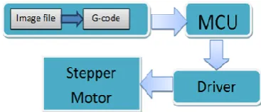
A CNC plotter is able to draw complex line drawings. The coordinates are uploaded to the machine controller by a separate program. The image file is transformed into a G-code via Software. Then the code is transferred to the microcontroller by which the motor mechanism is instructed to draw the image. In this project, we are going to present a simple design for a CNC plotter. Our idea is an Arduino based design using ATMEGA 328P microcontroller.
The machine will have three motors to implement the X, Y, and Z axis. A servo motor will be used along the Z axis for positioning the pen which will go up for logic 0 and down for logic 1[1]. Drawing will be done on the X-Y plane where the positioning will be controlled by stepper motors.
System overview is provided in Fig. 1.
IV.SCHEMATIC ARRANGEMENT
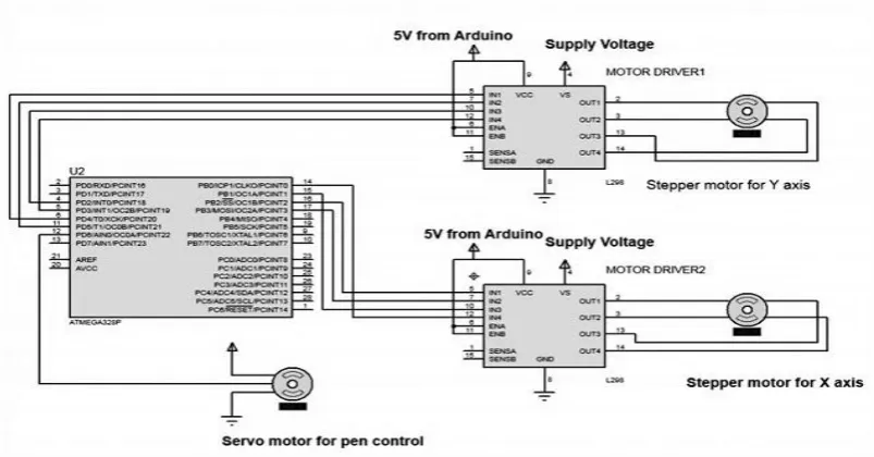
Fig 2: Schematic circuit diagram of CNC plotter
The Fig. 2 shows schematic circuit diagram of CNC plotter.
V.SOFTWARE AND CODING
To complete the task of entire project three software is used-
Inkscape
Fritzing.
Processing
A. Inkscape 0.48.5
Inkscape is used to design the plotted diagram or text. In this project by using this software G-code file of a selected image or text is created. G-code is a commonly used numerical control programming language which includes X, Y, Z coordinates.
Creating G-Code File Using Inkscape
The CNC plotter of our project will work within 20cm×20cm area.
Fig. 3 Conversion of text to G-code
So we choose the document properties of the Inkscape 40cmx40cm (Width×Height) which is four times the working area of the plotter because the plotter can draw only in the first quadrant.
So we have initially kept the axes at the nearest end of the motors which is considered as origin to easily modify the design.
In Fig. 3 the working area of CNC plotter is shown with the text written in the pre-defined area. The text is selected using cursor and then select “object to path” from the drop down window to save the G-code form of the selected text.
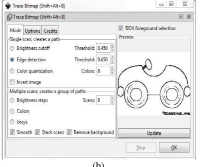
To create G-code of an image, the file must have a transparent background. The image should be dragged into the selected area then select “trace bitmap” from drop down window to create a transparent image. Scans are selected as 8 and “Edge detection” is selected to create black & white image. After adding this transparent image in the predefined area we‟ve used “object to path” command to create the G-code file of the selected image by following the steps described earlier.
(b)
Fig. 4 Creating transparent image (a) original image (b) transparent image.
Fig. 5 Conversion of transparent image to G-code
B. Fritzing
It is friendly open source circuit simulator software which is mainly used for PCB design.
Creating PCB Layout Using Fritzing
Using „Breadboard‟ option any circuit can be built easily by simply dragging and dropping down different components. Schematic circuit diagram and PCB layout will be generated automatically.
In PCB layout we need to choose positions of the components, their layers and establish connections. Then „Export for PCB‟ option is selected and choose „Etchable SVG‟ (Scalable Vector Graphics). From the saved folder the top layer mirror file is loaded. The file is automatically loaded in Inscape software and from there G-code will be generated as described earlier.
C. Processing
Processing is open source programming language software which is used for electronic drawings. GTCRL processing program is used to send G-code file from user interface to CNC plotter. The Fig. 6 shows the user interface of processing 2.2.1 software after running GTCRL program.
The port of Arduino Uno is selected by pressing „P‟ button on keyboard hence „G‟ button is used to
upload our desired G-code file. Immediately CNC machine will start sketching selected G-code file. Sketching can be stopped by pressing „X‟ button.
Fig. 6 Uploading G-code file
D. Coding
Bresenham's Line Algorithm is used for plotting in the CNC plotter. A part of this algorithm is shown below-
void line(int x0, int y0, int x1, int y1) {
int dx = abs(x1-x0), sx = x0<x1 ? 1 : -1; int dy = abs(y1-y0), sy = y0<y1 ? 1 : -1; int err = (dx>dy ? dx : -dy)/2, e2; for(;;){
setPixel(x0,y0);
if (x0==x1 && y0==y1) break; e2 = err;
if (e2 >-dx) { err -= dy; x0 += sx; } if (e2 < dy) { err += dx; y0 += sy; } }
}
Two stepper motor is used to control X and Y axis, and a servo motor is used to control the Z axis. The test code of Y axis stepper motor is shown below-
#include <Stepper.h>
const int stepsPerRevolution = 20; // Connection pins:
Stepper myStepperY(stepsPerRevolution, 2,3,4,5); void setup() {
// Set speed:
myStepperY.setSpeed(100);
// max 250 steps for dvd/cd stepper motor myStepperY.step(160);
delay(100); }
void loop() { }
arduino. The full CNC code is uploaded in the arduino then the arduino will wait for G-code file from processing software. When the processing software send command to arduino it will start plotting the G-code.
E. G-code
To draw a text file or design a circuit layout by the CNC plotter firstly the files need to be converted into G-Code. G-Code is a set of instruction that contains number of X, Y, Z, coordinates depending on the file. G-Code instructs X axis of the machine to travel from X1 to X2 points with a specific speed and same is true for Y axis, but for Z axis the coordinates are fixed because only vertically up & down movements are involved.
VI.HARDWARE IMPLEMENTATION
A. Mechanical Design of CNC Plotter Machine The two dimensional mechanical design of the body of CNC plotter is shown in Fig. 7
Fig. 7 Mechanical design of CNC plotter
B. Stock Materials • Wood
• Melamine board • PVC board • Metal rod
C. Components Required
To erect the CNC plotter machine, the required components are listed below:
• Stepper motor ( 2 pieces) • Motor driver module (2 pieces) • Servo motor
• Power supply • Arduino uno • Gears • Pen
• Hose Clamp • Bread board • PCB
• Connectors and Cables • Diodes
D. Mechanical Body Description
1) Motor Mount
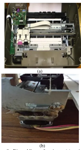
Two inkjet printers (HP1000) have been disassembled and their printing mechanism units
have been collected. One of which will act as X axis and the other as Y axis.
(a)
(b)
Fig. 8 Dissembling of printer (a) printing mechanism (b) Stepper motor mount
Printing mechanism unit contains a rigid metal frame which has a DC motor attached with a plastic gear on its shaft shown in Fig. 8a. Two gears are coupled via a belt on which the cartridge tray is connected. The cartridge moves to and fro with the movement of the motor. The DC motor is dismounted and replaced by a stepper motor shown in Fig. 8b. The stepper motor needs to be carefully aligned accurately with the furthest gear with which it is to be coupled. With the help of a glue gun the stepper motor has been fixed in a rigid position. Same procedure is followed for the other printing mechanism unit.
2) Axis Mount
Y-axis: A melamine board (61cm X 52cm) has been used for the base. The Y-axis has been mounted on the board maintaining a ground clearance of 4.8 cm because of the height of stepper motor. An A4 size PVC board has been placed on the tray with one end fixed on the tray and the other end on a metal rod so that the tray can easily move with the embedded board to and fro with less friction shown in Fig. 9. The level of the board has been carefully checked with a meter rule so that it is perfectly horizontal with the base. As a result the pen moves smoothly on the board without interruption.
X
Y
Fig. 9 Complete Y-axis
X-axis: X-axis basically moves the pen to and fro to cover the x-coordinates of the G-code. The X-axis has been placed perpendicular to the Y-axis lifted up by two wood legs of equal length shown in Fig. 10. A distance of 15 cm is kept from the starting point of the X-axis so that the Z-axis, which is mounted on the X-axis and holds the pen, is positioned at the center of the PVC board where both the axes X and Y has been centered.
Fig. 10 Mounted X axis on Y axis
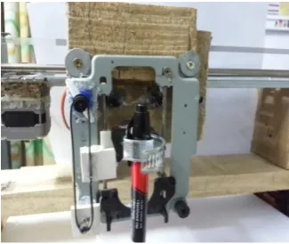
Z-Axis: A PC DVD drive has been disassembled and its stepper motor has been replaced with a servo motor. A gear has been worn on the spindle of the servo motor. A belt has been used to connect the gear with a pole and the belt has been glued with the moving mechanism of the DVD drive attached to a hose clamp. The Z-axis is mounted with the X-axis on the moving cartridge tray shown in Fig. 11 with caution so that it remains perfectly perpendicular with the X-axis during operation.
Fig. 11 Mounted Z axis with X axis
E. Complete CNC Plotter
After all those mounting of motors with the printing mechanism unit and axis with each other also with basement implementation become completed. The Fig. 12 shows complete CNC plotter.
Fig. 12 A complete CNC plotter
F. Calibration
After finishing the complete build-up of the machine, it is necessary to calibrate the movement of the axes. Test code for stepper motor mentioned in the section IV (D) is used where stepper motor‟s steps per revolution was 20 and 160 steps were allowed for the motor to travel. On running the code, it is found that the motor has travelled 26.5 mm which indicates that the motor takes 6 steps to cover 1mm. this is how calibration is done for both X and Y axes.
VII.RESULTS AND DISCUSSION
A. Text File
A text file has been designed and sent to the CNC plotter for drawing the text. The original file and the plotted files are shown in the Fig. 13.
(a)
Fig. 13 Comparison of text file (a) original text (b) plotted text
B. Black & While Image File
The Fig. 14a shows a black and white image file which has been plotted by the plotter shown in Fig. 14b.
(a)
(b)
Fig. 14 Comparison of image file (a) original black & white image (b) plotted image
C. Colourful Image File
Fig. 15a shows a colorful image file that has been converted into a sketch through bitmapping and edge detection and then plotted via CNC plotter machine shown in Fig. 15b.
(a)
(b)
Fig. 15 Comparison of image file (a) original image (b) plotted image.
D. PCB Layout
The Fig. 16a shows PCB layout that has been drawn on PC and Fig. 16b shows the one which is
plotted by the plotter. We can see that the layout is accurately drawn by the plotter with only slight error by a few mm in two places.
(a)
(b)
Fig. 16 PCB layout by (a) Inscape (b) plotter on copper clad.
VIII. LIMITATION
The machine runs in a slow pace and generates excess heat which causes the heat sink to be heated quickly. A slight error may remain on the image file after it has been plotted due to one side of the Y-axis fixed to the moving mechanism and the other end is free to move. The Z-axis is not very rigid so it causes slight vibration.
IX. FUTURE SCOPE
The pen of the machine can be replaced by a laser to make it work like a laser engraving or cutting machine. Engraving machine can be used on wood. The pen can also be replaced with a powerful drill so that it can be used for both milling and drilling purposes. The servo can be replaced with a stepper motor and the pen with a 3-D pen to make it a 3-D printer which can print objects with dimensions. By extrapolation of the axes, the working area of the machine can be extended keeping the algorithm unaltered.
X. CONCLUSION
low power and works with high accuracy due to precise controlling of stepper motors. This is a low cost project as compared to other CNC product. It is made with easily available components and spare parts. It is designed for private manufacturing and small scale applications in educational institutes. The machine is designed with a very simple construction scheme and can be carried anywhere without much effort. The algorithm used is simple. The pen can be replaced with a pinhead or laser head or any other tool for different purpose of use. Software that has been used is open source and user-friendly.
REFERENCES
[1] madekar, kajal j., et al. "automatic mini cnc machine for pcb
drawing and drilling." (2016).
[2] linggarjati, jimmy, and rinda hedwig. "manually interchangeable heads of homemade computer numerical control
(cnc) machine." internetworking indonesia journal 1.1 (2013).
[3] m.r. wright, d.e. platts, d.b. french, g. traicoff, m.a. dupont, andg.a. head,“cnc control systempatents,” us patent 545393, sep 26,1995.
[4] torjus spilling “self-improving cnc milling machine” university
of oslo (2014)
[5] neje 200mw mini diy laser engraving machine cnc laser print
er
[6] Industrialsuppliesonline.net/craftsman-cnc-router
[7] geocities.ws/industrialmarketplace/cnc-machines
[8] arduino.cc/en/Main/ArduinoBoardUno
[9] en.wikipedia.org/wiki/ATmega328
[10] dual full-bridge driver. multiwatt15. ordering numbers : l298n (multiwatt vert.) l298hn
[11] sg90 9 g micro servo. tiny and lightweight with high output power.
[12] stepper motor sth-39d1126-06 1.8deg/step 2 phase hybrid stepping motor electric motor step motor cnc
[13] en.wikipedia.org/wiki/Power_supply_unit_(computer)
[14] w. bosshart, printed circuit boards. new delhi: tata mcgrawhill,1983.