7109
Neural Network Based Vehicle Longitudinal
Controller – Design And Validation Using
Hardware In Loop Testing
Paul Sathiyan, Merry Cherian, Benin Pratap
Abstract: Adaptive Cruise Control System (ACC) is an automotive feature that allows the vehicle speed to automatically adjust to the speed of the lead vehicle and maintain a safe distance avoiding rear end collision. ACC is implemented using Neural Network Controller and the hardware implementation is done using dSPACE DS1103. The input of the Neural Network Controlled ACC is speed error. The actual distance between the vehicle equipped with ACC (host vehicle) and the lead vehicle is measured by using range sensor and speed of the vehicle is measured using proximity sensor. The dSPACE controller is used for the real time testing of the ACC system and performance of the system is studied by logging the required information. The controller output is obtained as throttle value and brake value which is given to the respective actuators to accelerate and decelerate the vehicle according to the spacing between the lead and the host vehicles.
Index Terms: Adaptive Cruise Controller, Back Propagation Neural Network, Collision Avoidance, Hardware In Loop Testing —————————— ——————————
1.
INTRODUCTION
In recent years many studies have been devoted to problem such as accident prevention, traffic flow smoothing. Mentally driving is a highly demanding activity. The driver must maintain a high degree of concentration for longer periods and swift to react within a split second according to the rising demand on the road. Fatalities on roads are basically because of driver’s fault [1]. Misjudgment, over speeding, the too close following of a lead vehicle, lack of driver’s attention to traffic changes, lack of lane discipline is some of the major reasons for the crash. Rear end collision was the most widely recognized crash sort that happens all around consistently [2], [3]. According to [4], a major percentage of the road traffic crash in India, occurred on state and national highways due to rear end collision. Percentage of rear end collisions were found higher in 4 and 6 lane divided highways. Accidents on the roads can be reduced to a greater degree with ADAS while driving in urban, rural and highway operating zones [5]–[7], which has been the important goal of the automotive industry [8]. ADAS provides important and critical information to the driver, automates tasks that require extreme human precision with the goal of inciting road safety [9]. Several driving assistance systems has been developed so far to assist the drivers, among them Vehicle Longitudinal Controller (VLC) aka Adaptive Cruise Controller (ACC) had been developed to reduce rear end collision with the vehicle travelling in the same lane.
2.
VEHICLE
LONGITUDINAL
CONTROLLER
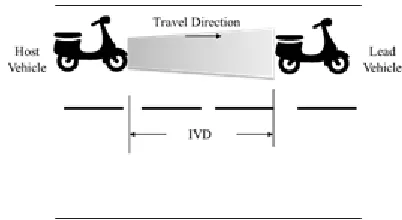
Fig 1. picturizes the vehicle following scenario. According to [10], number of tuning variables increases with the key performance characteristics (Safety, Comfort and Vehicle tracking/following) as the controller design depends on them. Controller design becomes even complex when contradicting parameters like comfort, safety, fuel economy is considered to arrive at an optimal design for the controller [10], [11]. The ACC system decides depending on which vehicle (usually the closest vehicle on the same lane) it will control the host vehicle and delivers information on the selected vehicle to the speed regulator of the host vehicle.
Fig. 1. Vehicle following scenario
7110
computational cost and heavy time requirement for computation. Arriving at a mathematical controller which functions more like a human is challenging. The degree to which the assistive system mimics the human driving behavior will influence drivers acceptance [17]. Since computational models with Artificial Neural Network mimic human behavior, such systems will have high degree of acceptance among the user. Hence in this research work the Artificial Neural Network with Back Propagation training is adopted for implementing VLC. The validation of the proposed control algorithm is performed using Hardware In Loop (HIL) testing.
3.
ARTIFICIAL
NEURAL
NETWORK
FOR
VLC
Computational models with Artificial Neural Network (ANN) mimic human behavior, such systems will have high degree of acceptance among the user. ANN has the capacity to process the information faster with a response time in nanoseconds. Adaptive learning ability prepares the network to gain experience through the given data [18]. Neural network is formed from artificial neurons interconnecting each other working in unison to supply outputs and it adapts to system with the info given thereto by making the synaptic connection adjustments that exist between the neurons. In most cases a neural network is an adaptive system changing its structure during a learning phase. Fig. 2 shows the architecture of ANN.
Fig. 2. Typical architecture of ANN
The following three types of parameters are used for defining an ANN [19].
How different layers of neurons are interconnected
How the weights are updated to reduce the error during training and the learning process involved behind.
How the output activation is achieved from the neuron’s weighted input by using the activation function
In a multilayer NN, Backpropagation Network (BPN) used. It is an upgraded version of gradient-based delta learning rule. The error obtained at the output layer is propagated backward to the input layer via the hidden layer. In BPN alteration of the connection weights are realized by gradient descent and mean square error.
3.1 Back Propagation Learning Process
The algorithm can be better understandable based on the direction of the signal flow. When the input signal is propagating in the forward direction to the output layer via the hidden layer, the bias value and the weight value of the network are maintained constant. The status of each layer of the neuron will only cause an effect on the neuron of the following layer. In case if the output deviates from the expected output, the error signal (deviation) is propagated back to the input layer form the output layer in a layer by layer manner. At this time the weights of the network are regulated by the error feedback and the process continues till the real output matches the expected output with some degree of deviation. The weight and the threshold values are adjusted with the help of the following function,
𝑋 = 𝑋 − 𝑔
Matrix of current weight and threshold values are represented in 𝑋 , gradient of current function is represented by 𝑔 and the learning rated is represented .
3.2 Training BPNN for VLC
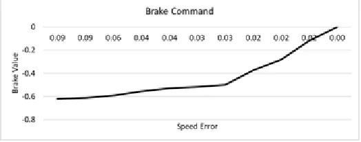
The input to the controller is Speed Error, the output of the controller is Throttle / Brake Command. Based on the data collected from the earlier research, the proposed controller is tuned with 80 % of the available data and tested using the remaining 20 % of data. Fig.3 and 4 shows the relationship of speed error vs throttle command and speed error vs brake command.
Fig. 3. Training data (Speed error vs throttle command)
Fig. 4. Training data (Speed error vs brake command)
4.
HARDWARE
IN
LOOP
TESTING
FOR
VALIDATION
7111
rear wheel. The specification of the test vehicle is presented in Table. 1.
Fig. 5. Test vehicle with NN based ACC.
TABLE1
SPECIFICATION OF TEST VEHICLE
Parameters Model / Range
Vehicle Model TVS Champ
Engine Capacity 69.9 cc
Kerb Weight (kg) 66
Fuel Type Petrol
Maximum Torque 5 Nm @ 3,750 rpm
Top Speed (km/hr) 50
Maximum Power 3.5 bhp @ 5000 rpm
Tire Radius (m) 0.4064
The proposed algorithm has been dumped on to a dSPACE controller for real time testing. In order to provide the two required inputs for the NN controller, the speed of the vehicle and the distance between the vehicles (host and the target vehicles) are sensed using the following sensors
1 Proximity Sensor 2 Ultrasonic Sensor
4.1 Proximity Sensor
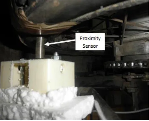
Proximity sensor is used to measure the speed of the vehicle. It is attached to the wheel of the host vehicle so that pulses are being counted out for a revolution and corresponding speed of the wheel is being found out. Proximity sensor responds to ferrous and nonferrous metal objects. It consists of an oscillator circuit and the output circuit (switching device). Oscillator circuit is the inductance coil creating a magnetic field. When the obstacle (metal object) is detected, immediately it responds either by opening or closing the switch. This creates a voltage variation at the sensor output. In order to improve the accuracy of the speed measurement at lower speeds, metal plates are fixed at the four quarters of the rear wheel. This produces four pulses for one rotation of the wheel. Fig. 6 shows how the proximity sensor and the sensing plates are fixed for speed measurement process.
Fig. 6. Arrangement of proximity sensor in vehicle
4.2 Ultrasonic Sensor
Scale down version of the range sensor used in this research to test the proposed algorithm in real time. Ultrasonic sensor MB1340 is preferred over the other sensors, because it has a real time analog voltage envelope. Table 2 provides the specification of the sensor.
TABLE2
SPECIFICATION OF ULTRASONIC SENSOR
Range (m) Accuracy (m) Output format refresh Data rate
Sensor opting frequency
0.15 - 6.45
m ±0.01
Real time analog voltage
envelope / Serial
Upto
100 ms 42 kHz
The presence of the obstacle / the lead vehicle is detected and the response is obtained in terms of varying voltage. Test is performed to study about the input and output response of the sensor. The results obtained are presented in Table 3.
TABLE3
SENSOR OUTPUT VOLTAGE VS DISTANCE BETWEEN THE SENSOR AND THE OBSTACLE
Meter scale in cm Output Voltage in Volts
20 0.080
50 0.220
100 0.432
150 0.652
200 0.856
250 1.08
300 1.29
350 1.51
400 1.72
50 1.94
500 2.16
550 2.37
7112
The range varies from 2m to 6.45m. The accuracy is high when it is being compared to the other sensors.
4.3 Throttle Actuator
The control signals received from the controller are fed to the plant to actuate the throttle and the brake to ensure safe vehicle following. The throttle actuator is used for the acceleration of the host vehicle. Fig. 7 presents the arrangement made for Throttle Actuator with feedback mechanism. This is performed with the help of pulley arrangement. One end of the pulley is connected to the shaft of the motor and the other end is connected to the potentiometer. The throttle wire is attached to the pulley. As the throttle command is received from the controller, the motor rotates the pulley, pulling the throttle wire which in turn opens / closes the throttle value. Thus, regulating the speed of the vehicle.
Fig. 7. Throttle actuator arrangement for vehicle acceleration
A Potentiometer is used to sense the position of the throttle. A 5V DC supply is provided for the potentiometer. A 10 kOhm potentiometer is used for this purpose. For a fully closed throttle, the output voltage at the potentiometer reads 2.8V and for a fully open throttle the potentiometer reads 4.3V. This voltage is given as a feedback to the system to ensure that the throttle actuator has responded to the command given by the controller. Table 4 shows the relation between the throttle position and the speed of the vehicle.
TABLE4
THROTTLE POSITION SENSOR VALUE VS VEHICLE SPEED Throttle Position
(v) Wheel Speed (r.p.m) Vehicle Speed (km/hr)
3.5 136.5 14
3.6 170.5 17.5
3.7 204.5 21
3.75 224 23
3.8 243.6 25
3.9 282.65 29
4 321.6 33
4.1 360.6 37
4.2 399.6 41
4.3 438.5 45
4.4 Hardware In-Loop Testing
The Hardware In-Loop testing is performed in order to validate the proposed controller. This procedure reduces the development time and improves the testing effectiveness. Fig. 8 presents the block diagram of the HIL testing performed in this research work where the test uses a real plant as discussed earlier.
Fig. 8. Block diagram of HIL testing
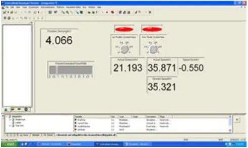
The preliminary control design is carried out and the I/Os are specified in the control model developed. Then the real time code for the model is created and dumped in to the dSPACE controller. On opening the GUI part of the control desk software, the process of acquiring the signal (Speed, distance) are configured. Fig. 9 gives the screenshot of the Graphical User Interface (GUI) developed to control and monitor the testing process. dSPACE Controldesk software is used for accomplishing this task.
Fig. 9. Screen shot of GUI developed in dSPACE Controldesk for testing
7113
Real-Time Interface to Simulink, and Real-Time Workshop, all located on the workstation PC. The control algorithm is downloaded onto the Texas Instruments’ TM320F240 DSP located on the DS1103 board.
5.
RESULTS
AND
DISCUSSION
During the test the distance between the host and the lead vehicle is varied. The controller on receiving the input, computes the required throttle and brake to maintain a safer distance during following a lead vehicle avoiding rear end collision. Fig. 10 gives the actual distance between the vehicles.
Fig. 10. Time vs measured distance
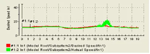
Fig. 11 shows the plot between the actual speed of the vehicle and the desired speed. There were disturbances observed in the graph due to vibration of the vehicle which was reflecting in the graph. Due to this the vehicle was tested up to a maximum speed of 35 km/hr. Overall the controller was able to perform satisfactorily.
Fig. 12. Actual and desired speed graphs
6.
CONCLUSION
The Adaptive Cruise Control (ACC) System with Back Propagation Network (BPN) was developed to maintain a safe distance between the lead vehicle avoiding rear end collision. The validation of the controller is performed using HIL testing with dSPACE. Speed error and distance error was given as an input to the controller. The output obtained from the controller was the amount of throttle and brake to be provided for safe control of the vehicle. TVS Champ is used as a test vehicle the proposed controller is implemented and the performance have been tested. The results show a satisfactory response, where the vehicle follows the lead vehicle based on the actual distance measured between the target and the host vehicle. In future, the performance of the proposed controller will be tested on road, the same will be upgraded to four wheelers.
REFERENCES
[1]. A. K. Yadav and J. Szpytko, ―Safety problems in vehicles with adaptive cruise control system,‖ J. Konbin, vol. 42, no. 1, pp. 389–398, 2017, doi:
10.1515/jok-2017-0035.
[2]. I. Isaksson-Hellman and M. Lindman, ―The effect of a low-speed automatic brake system estimated from real life data.,‖ in Annals of advances in automotive medicine / Annual Scientific Conference Association for the Advancement of Automotive Medicine. Association for the Advancement of Automotive Medicine. Scientific Conference, 2012, vol. 56, pp. 231–40.
[3]. V. Jirovský, ―Classification of road accidents from the perspective of vehicle safety sytems,‖ J. Middle Eur. Constr. Des. Cars J. Czech Tech. Univ., vol. 13, no. 2, pp. 1–9, 2015, doi: 10.1515/mecdc-2015-0005. [4]. D. Mohan, T. Geetam, and K. Bhalla, ―Road Safety in
India: Status Report,‖ Delhi, 2015.
[5]. S. K. Gehrig and F. J. Stein, ―Collision avoidance for vehicle-following systems,‖ IEEE Trans. Intell. Transp. Syst., vol. 8, no. 2, pp. 233–244, 2007, doi: 10.1109/TITS.2006.888594.
[6]. M. Ruikar, ―National statistics of road traffic accidents in India,‖ J. Orthop. Traumatol. Rehabil., vol. 6, no. 1, pp. 1–6, 2013, doi: 10.4103/0975-7341.118718. [7]. L. Shengbo, L. Keqiang, R. Rajamani, and J. Wang,
―Model Predictive Multi-objective Vehicular Adaptive Cruise Control,‖ IEEE Trans. Control Syst. Technol., vol. 19, no. 3, pp. 556–566, 2011, doi: 10.1109/TCST.2010.2049203.
[8]. S. Magdici and M. Althoff, ―Adaptive Cruise Control with Safety Guarantees for Autonomous Vehicles,‖ IFAC-PapersOnLine, vol. 50, no. 1, pp. 5774–5781, 2017, doi: 10.1016/j.ifacol.2017.08.418.
[9]. N. A. Chandramohan, ―Design and modeling of adaptive cruise control system using Petri Nets with fault tolerance capabilities,‖ no. May, 2018.
[10]. G. J. L. Naus, J. Ploeg, M. J. G. Van De Molengraft, W. P. M. H. Heemels, and M. Steinbuch, ―Control Engineering Practice Design and implementation of parameterized adaptive cruise control : An explicit model predictive control approach,‖ Control Eng. Pract., vol. 18, no. 8, pp. 882–892, 2010, doi: 10.1016/j.conengprac.2010.03.012.
[11]. M. Wang, M. Treiber, W. Daamen, B. van Arem, and B. van Arem, ―Modelling Supported Driving as an Optimal Control Cycle: Framework and Model Characteristics,‖ Procedia - Soc. Behav. Sci., vol. 80,
pp. 491–511, 2013, doi:
10.1016/j.sbspro.2013.05.027.
[12]. R. Abdullah, A. Hussain, K. Warwick, and A. Zayed, ―Autonomous intelligent cruise control using a novel multiple-controller framework incorporating fuzzy-logic-based switching and tuning,‖ Neurocomputing, vol. 71, no. 13–15, pp. 2727–2741, 2008, doi: 10.1016/j.neucom.2007.05.016.
[13]. I. Ciglaric and I. Prebil, ―Vehicle Dynamics Simulation , Part 1 : Mathematical Model,‖ pp. 1135–1144, 2002. [14]. K. S. Narendra and C. Xiang, ―Adaptive Control of Discrete-time Systems Using Multiple Models,‖ in 37th IEEE Conference on Decision & Control, 1998, no. December, pp. 3978–3983.
7114
10.1016/j.conengprac.2011.09.005.
[16]. V. Milanés et al., ―Comparing fuzzy and intelligent PI controllers in stop-and-go manoeuvres,‖ IEEE Trans. Control Syst. Technol., vol. 20, no. 3, pp. 770–778, 2012, doi: 10.1109/TCST.2011.2135859.
[17]. C. J. G. Van Driel, M. Hoedemaeker, and B. van Arem, ―Impacts of a Congestion Assistant on driving behaviour and acceptance using a driving simulator,‖ Transp. Res. Part F Traffic Psychol. Behav. Elsevier, vol. 10, no. 2, pp. 139–152, 2007, doi: 10.1016/j.trf.2006.08.003.
[18]. Z. Pezeshki and S. M. Mazinani, ―Comparison of artificial neural networks, fuzzy logic and neuro fuzzy for predicting optimization of building thermal consumption: a survey,‖ Artif. Intell. Rev., vol. 52, no. 1, pp. 495–525, 2019, doi: 10.1007/s10462-018-9630-6.