HEAT TRANSFER AUGMENTATION WITH ARRAY
OF MULTIPLE WATER JETS
Dr Niranjan Murthy
Associate Professor, Dept of Mechanical Engg.,
M.S.Ramaiah Institute of Technology, Bangalore (India)
ABSTRACT
Direct contact cooling using jet impingement is considered as the most effective method. The problem is complex and better understanding of jet impingement method is essential for proper application of this method for cooling. Present investigation was carried out by employing 0.5mm diameter water jets arranged in an array of 7X7 with a pitch of 3mm. The heat flux in the range of 25 to 200W/cm2 which is typical for electronic components was dissipated using multiple water jets. Temperature difference between the test plate and the coolant was within 300C during the experiment. Tests were performed in the flow rate range of 22 to 40 ml/min. Results show that heat flux is the dominating factor in determining the heat transfer.
Keywords:
Multiple water jet cooling, Heat transfer enhancement
I. INTRODUCTION
Large numbers of industries are interested in high speed computing. Most of the industries considered the
cooling of electronic components as a thermal management problem and tried to solve it by incorporating the
heat sinks. The requirements of high speed initiated smaller devices and systems. The speed of the personal
computers is increasing constantly and is reaching a point where traditional cooling methods are insufficient.
Because of this concern, the electronic world is looking for new and more effective cooling techniques. The
solution to this problem may be through the introduction of new materials, latest cooling technologies and
change in cooling technology concepts and methods of execution
.
Impinging jets for direct liquid cooling of microelectronic components has been investigated by many
researchers. Elison and Webb [1] experimentally investigated the heat transfer associated with a single water jet. The authors have tested three different nozzles having jet diameters of 0.584, 0.315 and 0.246mm.The nozzles
were long enough to allow a fully developed velocity profile in any regime. The range of Reynolds number (Re)
was between 300 and 7000. Nusselt number (Nu) varied as Re 0.8, where as the previous studies [1] have shown
that (Nu) is proportional to (Re)0.5. Authors have attributed the enhancement in heat transfer to the surface
tension effects at the nozzle exit, which is found to increase with increase in jet diameter.
Matteo Fabbri, Shanjuan Jiang, Vijay K. Dhir [2] conducted a study of cooling using both jets and sprays. The authors have investigated the performances of both sprays and micro jets and the comparison of results has been
presented. The following conclusions were made: (a)Micro-jet arrays can have the same or better performance
and wall- to- liquid temperature difference of 760 C, the jets could remove heat fluxes as high as 240W/cm2,
while the spray could remove only 93 W/cm2 (c) In practice, there is always a combination of jet diameter and
jet spacing that can yield the same heat transfer coefficients as that of the spray, but at much lower pumping
energy costs and (d) A highly populated micro jet arrays were much more preferable than the arrays with few
and large jets, because they needed a much lower flow rate to obtain the same heat removal rate.
Womac et al [3] performed experiments with 2x2 and 3x3 jet arrays using water and FC77as cooling fluids. The
impinging surface made of copper was a 12.7x12.7 mm2. Tests were conducted with jet diameters of 0.513 and
1.02 mm and pitches of 5.08 and 10.16 mm. It was found that for a given flow rate, the heat transfer improved
with the increase in jet velocity. It was also observed that the reduction in heat transfer that occurs with lowering
the flow rate becomes more pronounced at very low flow rates and authors have attributed this effect to the
bulk heating of the fluid. Wang et al. [4] used micro-jet heat sinks to cool VLSI chips. Micro-jet heat sinks can improve temperature uniformity in the presence of chip hot spots. Experimental comparison of micro-jet and
micro-channel performance showed that micro-jets have improved thermal uniformity. The results suggested
that micro-jet arrays are the preferred micro heat sinks for effective device cooling.
II. NOMENCLATURE
A Test plate surface area (cm2)
d Jet nozzle diameter (mm)
h Heat transfer coefficient (W/cm2C) ( q / (Tc -Tw) )
k Thermal conductivity(W/mK)
Nu Nusselt number ( hd/k)
P Total heat transfer (W)
q Heat flux (W/cm2) (P/A )
Q Total flow rate (ml/min)
Re Reynolds number (Vd/ν)
Tb Bulk fluid temperature (
0 C)
Tc Test surface temperature (
0 C)
Ta Inlet air temperature (0C)
V Jet velocity (m/s)
ν Kinematic viscosity (Ns/m2)
Z Nozzle height from chip surface (mm)
∆T Difference in temoerature between the test surface and air at inlet (Tc –Ta ) (0 C)
steady flow to the nozzle head. It also serves to achieve fine control over the flow rate by adjusting pressure.
Safety valve is provided to prevent excess pressure build-up.
The heater assembly consists of hot plate, heating element, thermocouples, variable voltage transformer and a
control - display system. The hot plate represents the surface of an electronic component and is made of Copper.
Copper is chosen because of its high thermal conductivity. The hot plate is of 2cm x 2cm size and thickness
1mm.The hot plate was mounted on the heating element. The heating element is a Nichrome wire of 16 gauge,
2 ohm, and wattage capacity of 1 kW. The power to the heater was controlled using the variable voltage
transformer. Two thermocouples were mounted underneath the hot plate on the centre line and insulated with
ceramic insulation.These thermocouples also provide indication of surface temperature uniformity on the plate.
The complete heater assembly was mounted and insulated using a Teflon jacket. The leads from the
thermocouples were connected to the control - display system.
The control and display system performs the following functions:
Vary the heat input to the hot plate using the transformer.
Display the hot plate surface temperatures, input voltage and current using digital temperature indicator,
voltmeter and ammeter.
Limit the maximum surface temperature and automatically cut off the power supply when the hot plate
temperature exceeds the set value.
The Jet nozzle head is made of stainless steel and it consists of the nozzle chamber and nozzle plate. The nozzle
chamber was connected to the reservoir through a connecting tube. The nozzle plate is made of 3mm thick
stainless steel plate. The nozzle plate was designed to cover the nozzle chamber making it a single leak proof
unit. The nozzle plate had 49 holes, each of 0.5 mm diameter, which are laser drilled and arranged in a square
array of 7X7 with a pitch distance of 3mm between the holes. The distance between the nozzle plate and the hot
plate surface can be varied. The test stand consists of base tray, mounting plate, hot plate, movable nozzle plate
and a top plate held together by vertical supporting rods. The nozzle head is attached to the nozzle plate which
could be moved vertically. A calibrated screw – thread assembly is provided along with a circular scale on the
top plate. The nozzle plate could be set to the desired height by accurate positioning of the calibrated screw
head. Experiments were conducted by positioning the jets and the hot plate in both horizontal and vertical
positions.
The hot plate surface is cleaned to remove residual adhesive stains and dust on the surface before the
experiment. Compressed air is passed through the tube connecting the reservoir and the nozzle head to remove
any dust particles which could block the nozzle. The filter is installed in the flow line prior to the auxiliary
reservoir. The flow rate, power input and distance between nozzle exit and test hot plate were varied during the
experiments. The hot plate is allowed to reach steady state before acquisition of test data on water flow rate,
Fig1: Schematic diagram of multiple water jet experimental setup
IV. DATA ACQUISITION
The test plate was allowed to reach a steady state. The test data on air flow rate, velocity, power dissipation and
temperatures was acquired. Prior to the recording of the heat transfer data for analysis, experiment was
conducted to obtain the time required to reach the steady state. It was found that the average test plate
temperature was within 0.10C of its steady state value within 10 minutes of required power to the test plate. Test
surface temperature measurements were recorded using thermocouples which are mounted underneath of a test
surface. The fluid inlet temperature is recorded using a 1.5mm diameter type T thermocouple. The
thermocouples were calibrated prior to installation and measurements were compared. The wattmeter was used
to measure the heat flux input to the test plate.
V. RESULTS AND DISCUSSIONS
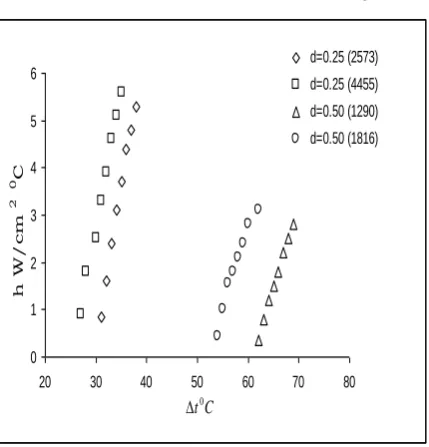
Figs 1 and 2 show the comparison of results obtained with different jet diameters. Significant effect of jet
diameter has been noticed. Higher values of heat transfer coefficient are obtained with the lower diameter jets.
This is possibly due to the reason that as the jet proceeds towards the impingement region, the thickness of
0 1 2 3 4 5 6
20 30 40 50 60 70 80
h W / c m 2 0 C d=0.25 (2573) d=0.25 (4455) d=0.50 (1290) d=0.50 (1816) C t0
Fig 1: Variation of heat transfer co-efficient with temperature difference for different Reynolds
numbers at Z=10mm for horizontal jets.
0 1 2 3 4 5 6
20 30 40 50 60 70 80
h W / c m 2 0C d=0.25 (2573) d=0.25 (4455) d=0.50 (1290) d=0.50 (1816) C t0
Fig 2: Variation of heat transfer co-efficient with temperature difference for different Reynolds
numbers at Z=20mm for horizontal jets.
With the jet diameter of 0.25mm, lower values of (Δt) have been obtained. Although the tests have been carried
out with different jet diameters, the plots show consistent variations with Reynolds number.
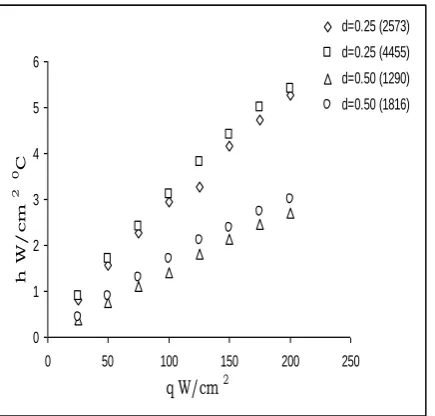
Figs 3and 4 show the comparison of results obtained using d=0.5mm and d=0.25mm diameter jets. It is evident
that higher values of heat transfer coefficient are obtained with a 0.25mm diameter jet as compared to 0.50mm
0 1 2 3 4 5 6
0 50 100 150 200 250
q W/cm 2
h
W
/
c
m
2
0 C
d=0.25 (2573)
d=0.25 (4455)
d=0.50 (1290)
d=0.50 (1816)
Fig 3: Variation of heat transfer co-efficient with heat flux for different Reynolds numbers for
horizontal jets at Z=10mm
0 1 2 3 4 5 6
0 50 100 150 200 250
q W/cm 2
h
W
/
c
m
2
0C
d=0.25 (2573)
d=0.25 (4455)
d=0.50 (1290)
d=0.50 (1816)
Fig 4: Variation of heat transfer co-efficient with heat flux for different Reynolds numbers for
horizontal jets at Z=20mm
IV. CONCLUSION
Experiments were conducted to study the enhancement of heat transfer using impingement of multiple water jets
on an electrically heated test plate. Heat flux in the range of 25 to 200W/cm2,which is typical for high power
REFERENCES
[1]. Elison, B.and Webb, B.W. “Local heat transfer to impinging liquid jets in the initially laminar, transitional, and turbulent regimes.” International Journal of Heat and Mass transfer, 37, no 8, (1994) pp.1207-1216. [2]. Matteo Fabbri, Shanjuan Jiang, Vijay K. Dhir; Comparative Study of Spray and Multiple Micro Jets
Cooling for High Power Density Electronic Applications;
[3]. Womac.D. J, Incropera.F. P and Ramadhyani.S; Correlating Equations for Impingement Cooling of Small
Heat Sources With Multiple Circular Liquid Jets; ASME J. Heat Transfer, 116, (1994) pp. 482–486.
[4]. Wang.E.N, Zhang.L, Jiang.L, Koo.J.M, Goodson.K. E, Kenny.T.W, Maveety.J. G, Sanchez.E.A;
Micro-machined Jet Arrays for Liquid Impingement Cooling of VLSI Chips, Solid-State Sensor, Actuator and
Microsystems Workshop; Hilton Head Island, South Carolina, June 2-6, 2002.
[5]. Uysal, U., Li, P. W., Chyu, M. K., Cunha, F. J., 2006, “Heat Transfer on Internal Surfaces of a Duct
Subjected to Impingement of a Jet Array with Varying Jet Hole-Size and Spacing,” ASME Journal of
Turbomachinery, Vol. 128, pp. 158-165.
[6]. Esposito, E. I., Ekkad, S. V., Kim, Y., Dutta, Partha, 2009, “Novel Jet Impingement Cooling Geometry for Combustor Liner Backside Cooling,” ASME Journal of Thermal Science and Engineering Applications,
Vol. 1, pp. 021001-1-8.
[7]. Moffat, R. J., 1988, “Describing the Uncertainties in Experimental Results,” Experimental Thermal and
Fluid Science, Vol. 1, pp.3-17.
[8]. Chambers, A. C., Gillespie D. R. H., Ireland P. T., Dailey G. M., 2005, “The Effect of Initial Cross Flow
on the Cooling Performance of a Narrow Impingement Channel,” ASME Journal of Heat Transfer, Vol.
127, pp. 358-365.
[9]. Kercher, D. M., Tabakoff, W., 1970, “Heat Transfer by a Square Array of Round Air Jets Impinging Perpendicular to a Flat Surface Including the Effect of Spent Air,” ASME Journal of Engineering for
Power, Vol. 92, pp. 73-82.
[10]. San, J. Y., Lai, M. D., 2001, “Optimum Jet-to-jet Spacing of Heat Transfer for Staggered Arrays of Impinging Air Jets,” International Journal of Heat and Mass Transfer, Vol. 44, pp 3997-4007.
[11]. Anwarullah.M., Vasudeva Rao.V., Sharma. K.V. “An Experimental Investigation on the Influence of the
Shape of the Nozzle for Flow Field and Heat Transfer Characteristics between Electronic Equipment
Surface and Confined Impinging Air Jet” International Journal of Dynamics of Fluids, Vol. 5, No. 2 m,