R}
CHAPTER 15
Organizational Level (O-Level) Maintenance Data System (MDS) Functions,
Responsibilities and Source Document Procedures
Table of Contents
R} 15.1 O-Level Maintenance Data System (MDS) Functions and Responsibilities ... 1
15.1.1 Maintenance Control Operating VIDS ... 1
15.1.1.1 Hardware ... 1
15.1.1.2 General Procedures ... 2
15.1.1.3 Operating Procedures ... 3
15.1.1.4 Phase Maintenance Procedures ... 5
15.1.1.5 Historical Files ... 6
15.1.1.6 Naval Flight Record Subsystem (NAVFLIRS) ... 6
15.1.1.7 MAF Work Request ... 7
15.1.1.8 Maintenance Division Officers ... 7
R} 15.1.2 Maintenance Control Operating NALCOMIS ... 8
15.1.2.1 Hardware ... 8
15.1.2.2 General Features ... 8
15.1.2.3 Operating Procedures ... 10
15.1.2.4 Phase Maintenance Procedures ... 11
15.1.2.5 Historical Files ... 12
15.1.2.6 Naval Flight Record Subsystem (NAVFLIRS) ... 12
15.1.2.7 MAF Work Request ... 13
15.1.2.8 Maintenance Division Officers ... 13
15.1.2.9 Work Center Supervisors ... 13
R} 15.2 O-Level Maintenance Source Document Procedures ... 14
15.2.1 Maintenance Action Documentation Procedures ... 14
15.2.1.1 Types of Maintenance Actions ... 14
15.2.1.2 Internal Flow ... 15
15.2.1.3 Data Field Description ... 16
15.2.2 Aircraft Inventory and Readiness Reporting System (AIRRS) ... 24
15.2.2.1 Definition of Terms ... 25
15.2.2.2 Inventory Reporting Transaction ... 25
15.2.3 Subsystem Capability and Impact Reporting (SCIR) System ... 27
15.2.3.1 Equipment Operational Capability (EOC) Codes ... 27
15.2.3.2 Mission Capability ... 27
15.2.3.4 Data Groups ... 28
15.2.3.5 Maintenance and Supply Definitions ... 28
15.2.3.6 Repair Cycle Documentation ... 29
15.2.3.7 Maintenance/Supply Record Documentation ... 29
15.2.3.8 Awaiting Maintenance Documentation ... 30
15.2.3.9 Change of Equipment Operational Capability (EOC) Code ... 30
15.2.3.10 Redundant Subsystems ... 30
15.2.3.11 SCIR Aspects of Inspection Documentation ... 30
15.2.3.12 Subsystem Capability and Impact Reporting (SCIR) Close Out ... 32
15.2.4 Aircraft Maintenance Documentation ... 32
15.2.4.1 Aircraft Repair ... 32
15.2.4.2 Aircraft Inspections ... 36
15.2.4.3 MAF Work Request ... 40
15.2.4.4 Technical Directive (TD) Compliance ... 40
15.2.5 Aircraft Engine and Airborne Auxiliary Power Unit (APU) Maintenance Documentation ... 41
15.2.5.1 Engine TD Compliance ... 42
15.2.5.2 Engine Cannibalization ... 42
15.2.5.3 Nondefective Repairable Engine Components ... 43
15.2.5.4 Engine Inspections ... 43
15.2.5.5 Unscheduled Engine Maintenance ... 43
15.2.6 Support Equipment Maintenance Documentation ... 44
15.2.7 Target Maintenance Documentation ... 44
15.2.8 Standard Rework Documentation ... 45
15.2.9 In-Service Repair (ISR) ... 45
15.2.10 Modification ... 46
R} 15.2.11 Documentation Examples ... 46
15.2.11.1 Aircraft Inventory Gain ... 46
15.2.11.2 Aircraft Inventory Loss (Transfer or Strike) ... 46
15.2.11.3 Aircraft Change in MCRS Status ... 47
15.2.11.4 End of Month Close Out MAF ... 47
15.2.11.5 Reinitiated MAF After Close Out ... 48
15.2.11.6 Excessive Troubleshooting ... 48
15.2.11.7 On-Equipment Repair ... 49
15.2.11.8 On-Equipment Repair (Repairable Component Replacement) ... 49
15.2.11.9 Turn-In of Repairables and Locally Repaired Consumables ... 50
15.2.11.10 Component Received Missing SRC Card ... 51
15.2.11.12 Cannibalization Action MAF ... 52
15.2.11.13 Matched System (Component 1) ... 52
15.2.11.14 Matched System (Component 2) ... 53
15.2.11.15 Assisting Work Center ... 54
15.2.11.16 Facilitate Other Maintenance (FOM) Action ... 54
15.2.11.17 Wheel and Tire Documentation ... 55
15.2.11.18 Wheel and Tire Turn-In Document ... 56
15.2.11.19 Aircraft Transfer or Strike (Close Out) ... 56
15.2.11.20 Hosting Activity Repair Document ... 57
15.2.11.21 Transient Maintenance SCIR Data ... 58
15.2.11.22 In-Flight Maintenance (No CDI) ... 58
15.2.11.23 Away From Home Maintenance (Excepting) ... 59
15.2.11.24 Removal and Replacement of Cartridges (CARTs), Cartridge Activated Devices (CADs), and Propellant Actuated Devices (PADs) (O-Level Maintenance) ... 59
15.2.11.25 Intra-Activity Support (1) ... 60
15.2.11.26 Intra-Activity Support (2) ... 61
15.2.11.27 Aircraft Mission or SE Reconfiguration ... 61
15.2.11.28 Acceptance Inspection ... 62
15.2.11.29 Acceptance Inspection (Fix In Place Discrepancy) ... 62
15.2.11.30 Acceptance Inspection (Repairable Required) ... 63
15.2.11.31 Transfer Inspection ... 64
15.2.11.32 Aircraft Phase Inspection (Check Crew Not Integrated) Control Document ... 64
15.2.11.33 Aircraft Phase Inspection (Multiple Inspection) Control Document ... 65
15.2.11.34 Aircraft Phase Inspection Man-Hours (Control and Look Phase) ... 65
15.2.11.35 Aircraft Fix Phase ... 66
15.2.11.36 Aircraft Special Inspection Control Document ... 67
15.2.11.37 Aircraft Special Inspection (Fix Phase) ... 67
15.2.11.38 Aircraft Conditional Inspection Control Document ... 68
15.2.11.39 Aircraft Conditional Inspection (Fix Phase) ... 68
15.2.11.40 Aircraft Preservation Control Document ... 69
15.2.11.41 Aircraft Depreservation (Work Center Action) ... 70
15.2.11.42 Inspection AWM (Close Out) ... 70
15.2.11.43 Combined Airframe and Engine Special Inspection Control Document ... 71
15.2.11.44 Combined Airframe and Engine Special Inspection Look Phase Document ... 71
15.2.11.45 Combined Airframe and Engine Special Inspection Look Phase Document for an Installed Engine ... 72
15.2.11.47 MAF Work Request Turn-In Document ... 73
15.2.11.48 Reinstallation After Check, Test, and Service ... 74
15.2.11.49 Conditional Inspection MAF Work Request (NDI On-Site) ... 74
15.2.11.50 MAF Work Request for ALSS and Other End Items ... 74
15.2.11.51 MAF Work Request Turn-In Document (Local Manufacture/Fabrication) ... 75
15.2.11.52 MAF Work Request Turn-In Document (No WUC/TEC) ... 75
15.2.11.53 TD Compliance (Maintenance Control Entries) ... 76
15.2.11.54 TD Compliance (Work Center Entries) ... 76
15.2.11.55 TD Compliance Turn-In Document (IMA Assist) ... 77
15.2.11.56 Transient Aircraft TD Compliance ... 77
15.2.11.57 Engine TD Compliance (Maintenance Control Entries) ... 78
15.2.11.58 Engine TD Compliance (Work Center Entries) ... 79
15.2.11.59 Engine Component TD Compliance (Installed) ... 79
15.2.11.60 Engine Component TD Compliance (Removal and Reinstallation Required) ... 80
15.2.11.61 SCIR Impacted TD Compliance (Installed Engine)... 80
15.2.11.62 TD Compliance (Transient Aircraft Engine) ... 81
15.2.11.63 Engine FOM for Removal and Reinstallation of Components for IMA TD Compliance ... 82
15.2.11.64 TD Compliance (Engine Removal and Reinstallation) ... 83
15.2.11.65 TD Compliance Engine Turn-In Document ... 83
15.2.11.66 TD Removals ... 84
15.2.11.67 Engine Component Cannibalization ... 84
15.2.11.68 Engine Cannibalization ... 85
15.2.11.69 Removal Action (Nondefective Repairable Engine Component) ... 85
15.2.11.70 Installation Action (Nondefective Repairable Engine Component)... 86
15.2.11.71 Removal and Replacement (Solely for IMA Inspection) ... 86
15.2.11.72 Turn-In Document (Engine Inspection) ... 87
15.2.11.73 Special Inspection Control Document ... 87
15.2.11.74 Special Inspection (Installed Engine) Look Phase Document ... 88
15.2.11.75 Special Inspection (Installed Engine) Fix Phase Document ... 89
15.2.11.76 Conditional Inspection (Installed Engine) Control Document ... 89
15.2.11.77 Conditional Inspection (Installed Engine) Look Phase Document ... 90
15.2.11.78 Conditional Inspection (Installed Engine) Fix Phase Document ... 91
15.2.11.79 Unscheduled Maintenance (Installed Engine) Repair Document ... 91
15.2.11.80 Unscheduled Maintenance (Installed Engine) Repairable Replacement ... 92
15.2.11.81 Installed APU Repair Document ... 93
15.2.11.82 Removal and Replacement of a Defective APU ... 93
15.2.11.84 Engine Turn-In Document (Unscheduled) ... 94
15.2.11.85 SE Technical Directive Compliance Turn-In Document ... 95
15.2.11.86 SE Inspection/Periodic Maintenance Turn-In Document ... 95
15.2.11.87 SE End Item Repair Turn-In Document ... 96
15.2.11.88 Target Postlaunch Rehabilitation Inspection (Look Phase) ... 96
15.2.11.89 Target Postlaunch Rehabilitation Inspection (Fix Phase) ... 97
15.2.11.90 Target Configuration Change ... 97
R} 15.2.11.91 Standard Rework Control Document ... 98
R} 15.2.11.92 Standard Rework Look Phase Document ... 98
15.2.11.93 Standard Rework Fix Phase Document ... 99
R} 15.2.11.94 In-Service Repair Document ... 100
R} 15.2.11.95 Modification Document ... 100
Figure 15-1: O-Level Maintenance Control Board ... 102
Figure 15-2: O-Level Maintenance Control Board (Using One Board Per Aircraft) ... 103
Figure 15-3: O-Level Maintenance Control Board (Side Nos.) ... 104
Figure 15-4: O-Level Maintenance Control Board (Side Nos. and W/Cs) ... 105
Figure 15-5: O-Level Maintenance Control Board Miscellaneous Section (By W/C) ... 106
Figure 15-6: O-Level Maintenance Control Board Miscellaneous Section (By TEC and SERNO) ... 107
Figure 15-7: O-Level Maintenance MAF Document Flow Chart ... 108
Figure 15-8: MAF Flow for O-Level IMRL Reported SE ... 109
Figure 15-9: NALCOMIS OMA Aircraft/Equipment Work Load Report... 110
Figure 15-10: NALCOMIS OMA Work Center Work Load Report ... 111
Figure 15-11: NALCOMIS OMA MAF Initiation Cycle ... 112
Figure 15-12: NALCOMIS OMA MAF Completion Cycle ... 113
Figure 15-13: Aircraft Transfer Report ... 114
Figure 15-14: Aviation 3M Data Cycles ... 115
Figure 15-15: NALCOMIS Organizational Maintenance Activity Maintenance Action Form ... 116
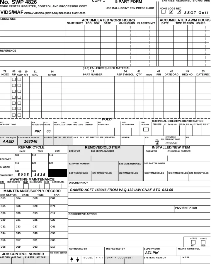
Figure 15-16 MAF (OPNAV 4790/60) ... 117
Figure 15-17 Aircraft Inventory Gain ... 118
Figure 15-18: Aircraft Inventory Loss (Transfer or Strike) ... 119
Figure 15-19: Aircraft Change in MCRS Status ... 120
Figure 15-20: Data Groups Required for SCIR ... 121
Figure 15-21: Maintenance vs Supply Situation (1) ... 122
Figure 15-22: Maintenance vs Supply Situation (2) ... 123
Figure 15-23: Maintenance vs Supply Situation (3) ... 124
Figure 15-24: Simple EOC Code Change ... 125
Figure 15-26: Redundant System Logic ... 127
Figure 15-27: Multiple Work Center Inspection Documentation ... 128
Figure 15-28: End of Month Close Out MAF ... 129
Figure 15-29: Reinitiated MAF After Close Out ... 130
Figure 15-30: Excessive Troubleshooting ... 131
Figure 15-31: On-Equipment Repair ... 132
Figure 15-32: On-Equipment Repair (Repairable Component Replacement) ... 133
Figure 15-33: Turn-In of Repairables and Locally Repaired Consumables ... 134
Figure 15-34: Component Received Missing SRC Card ... 135
Figure 15-35: Component Received Non-RFI and Installed ... 136
Figure 15-36: Cannibalization Action MAF ... 137
Figure 15-37: Matched System (Component 1) ... 138
Figure 15-38: Matched System (Component 2) ... 139
Figure 15-39: Assisting Work Center ... 140
Figure 15-40: Facilitate Other Maintenance Action ... 141
Figure 15-41: Wheel and Tire Documentation ... 142
Figure 15-42: Wheel and Tire Turn-In Document ... 143
Figure 15-43: Aircraft Transfer or Strike (Close Out) ... 144
Figure 15-44: Hosting Activity Repair Document ... 145
Figure 15-45: Transient Maintenance SCIR Data ... 146
Figure 15-46: In-Flight Maintenance (No CDI) ... 147
Figure 15-47: Away From Home Maintenance (Excepting) ... 148
Figure 15-48: Removal and Replacement of Cartridges, Cartridge Activated Devices, and Propellant Actuated Devices (Organizational Level Maintenance) ... 149
Figure 15-49: Intra-Activity Support (1)... 150
Figure 15-50: Intra-Activity Support (2)... 151
Figure 15-51: Aircraft Mission or SE Reconfiguration... 152
Figure 15-52: Acceptance Inspection... 153
Figure 15-53: Acceptance Inspection (Fix In Place Discrepancy) ... 154
Figure 15-54: Acceptance Inspection (Repairable Required) ... 155
Figure 15-55: Aircraft Transfer Inspection ... 156
Figure 15-56: Aircraft Phase Inspection (Check Crew Not Integrated) Control Document ... 157
Figure 15-57: Aircraft Phase Inspection (Multiple Inspection) Control Document ... 158
Figure 15-58: Aircraft Phase Inspection Man-Hours (Control and Look Phase) ... 159
Figure 15-59: Aircraft Fix Phase ... 160
Figure 15-60: Aircraft Special Inspection Control Document ... 161
Figure 15-62: Aircraft Conditional Inspection Control Document ... 163
Figure 15-63: Aircraft Conditional Inspection (Fix Phase) ... 164
Figure 15-64: Aircraft Preservation Control Document... 165
Figure 15-65: Aircraft Depreservation (Work Center Action) ... 166
Figure 15-66: Inspection AWM (Close Out) ... 167
Figure 15-67: Combined Airframe and Engine Special Inspection Control Document ... 168
Figure 15-68: Combined Airframe and Engine Special Inspection Look Phase Document ... 169
Figure 15-69: Combined Airframe and Engine Special Inspection Look Phase Document for an Installed Engine ... 170
Figure 15-70: Removal for Check, Test, and Service ... 171
Figure 15-71: MAF Work Request Turn-In Document ... 172
Figure 15-72: Reinstallation After Check, Test, and Service ... 173
Figure 15-73: Conditional Inspection MAF Work Request (NDI On-Site) ... 174
Figure 15-74: MAF Work Request for ALSS and Other End Items ... 175
Figure 15-75: MAF Work Request Turn-In Document (Local Manufacture/Fabrication) ... 176
Figure 15-76: MAF Work Request Turn-In Document (No WUC/TEC) ... 177
Figure 15-77: TD Compliance (Maintenance Control Entries) ... 178
Figure 15-78: TD Compliance (Work Center Entries) ... 179
Figure 15-79: TD Compliance Turn-In Document (IMA Assist) ... 180
Figure 15-80: Transient Aircraft TD Compliance ... 181
Figure 15-81: Engine TD Compliance (Maintenance Control Entries) ... 182
Figure 15-82: Engine TD Compliance (Work Center Entries) ... 183
Figure 15-83: Engine Component TD Compliance (Installed) ... 184
Figure 15-84: Engine Component TD Compliance (Removal and Reinstallation Required) ... 185
Figure 15-85: SCIR Impacted TD Compliance (Installed Engine) ... 186
Figure 15-86: TD Compliance (Transient Aircraft Engine) ... 187
Figure 15-87: Engine FOM for Removal and Reinstallation of Components for IMA TD Compliance ... 188
Figure 15-88: TD Compliance (Engine Removal and Reinstallation) ... 189
Figure 15-89: TD Compliance Engine Turn-In Document ... 190
Figure 15-90: TD Removals ... 191
Figure 15-91: Engine Component Cannibalization ... 192
Figure 15-92: Engine Cannibalization ... 193
Figure 15-93: Removal Action (Nondefective Repairable Engine Component) ... 194
Figure 15-94: Installation Action (Nondefective Repairable Engine Component) ... 195
Figure 15-95: Removal and Replacement (Solely for IMA Inspection) ... 196
Figure 15-96: Turn-In Document (Engine Inspection) ... 197
Figure 15-98: Special Inspection (Installed Engine) Look Phase Document ... 199
Figure 15-99: Special Inspection (Installed Engine) Fix Phase Document ... 200
Figure 15-100: Conditional Inspection (Installed Engine) Control Document ... 201
Figure 15-101: Conditional Inspection (Installed Engine) Look Phase Document ... 202
Figure 15-102: Conditional Inspection (Installed Engine) Fix Phase Document ... 203
Figure 15-103: Unscheduled Maintenance (Installed Engine) Repair Document ... 204
Figure 15-104: Unscheduled Maintenance (Installed Engine) Repairable Replacement ... 205
Figure 15-105: Installed APU Repair Document ... 206
Figure 15-106: Removal and Replacement of a Defective APU ... 207
Figure 15-107: Engine Component Turn-In Document ... 208
Figure 15-108: Engine Turn-In Document (Unscheduled) ... 209
Figure 15-109: SE Technical Directive Compliance Turn-In Document ... 210
Figure 15-110: SE Inspection/Periodic Maintenance Turn-In Document ... 211
Figure 15-111: SE End Item Repair Turn-In Document ... 212
Figure 15-112: Target Postlaunch Rehabilitation Inspection (Look Phase)... 213
Figure 15-113: Target Postlaunch Rehabilitation Inspection (Fix Phase) ... 214
Figure 15-114: Target Configuration Change ... 215
Figure 15-115: Standard Rework Control Document ... 216
Figure 15-116: Standard Rework Look Phase Document ... 217
Figure 15-117: Standard Rework Fix Phase Document (O-Level Repair) ... 218
Figure 15-118: Standard Rework Fix Phase Document (Primary) ... 219
Figure 15-119: In-Service Repair Document ... 220
R}
CHAPTER 15
Organizational Level (O-Level) Maintenance Data System (MDS) Functions,
Responsibilities and Source Document Procedures
R}
15.1 O-Level Maintenance Data System (MDS) Functions and Responsibilities
15.1.1 Maintenance Control Operating VIDS
a. The function of management has been defined as the "efficient attainment of enterprise objectives".
Maintenance has been defined as "all actions taken to retain material in a serviceable condition or to restore it
to serviceability". When these are combined, we can define maintenance management as "the actions
necessary to retain in or restore material or equipment to a serviceable condition with an optimum
expend-iture of resources".
b. It is the responsibility of all maintenance managers to manage their resources in an efficient manner.
To accomplish this task they shall maintain control of the various elements within their area of responsibility.
Effective control is dependent upon the availability of current status information on these elements. The
VIDS provides this information.
c. The VIDS is designed to require minimum manpower and paperwork, yet produce maximum status
information necessary for the control of maintenance. Communication between Maintenance Control, work
centers, and Material Control is essential to ensure the successful operation of the VIDS. Each time a change
of job status occurs, for example, from in work to AWM, and from in work to AWP, Maintenance Control
shall be notified immediately by the Work Center Supervisor.
d. The maintenance manager is concerned with aircraft status, operational commitments, aircrew
personal protective equipment status, SE status, workload requirements, and personnel assets. Efficient
operation requires a centralized control point through which all information concerning these areas must pass.
In an O-level activity this central point is Maintenance Control.
(1) The MMCO shall be responsible for the overall management of the maintenance effort. This
responsibility is exercised primarily through the various Production Division officers/supervisors.
(2) Maintenance Division officers shall be responsible for the actual productive effort within their
divisions. They shall keep the MMCO informed of any problems that can affect the department's/division's
output.
(3) The VIDS is a management tool that provides a graphic display of vital, up-to-date information
on a continuing basis. The system correlates all aircraft status information, particularly NMCS/PMCS,
flyable discrepancies, nonaircraft related discrepancies, for example, aircrew PPE and SE, and assigns a
relative importance to each item. The ability to review the overall situation and determine what resources are
available enables the aircraft MO and MMCO, or supervisor, to carry out their duties more effectively and
efficiently.
15.1.1.1 Hardware
15.1.1.1.1 VIDS boards are enlarged cardex type pockets for the visual display of weapon system status.
Each pocket is overlapped by the one above so that approximately 3/8-inch strip is visible at the bottom of
the pockets. Boards are currently available in three sizes; 100, 50, and 25 pocket.
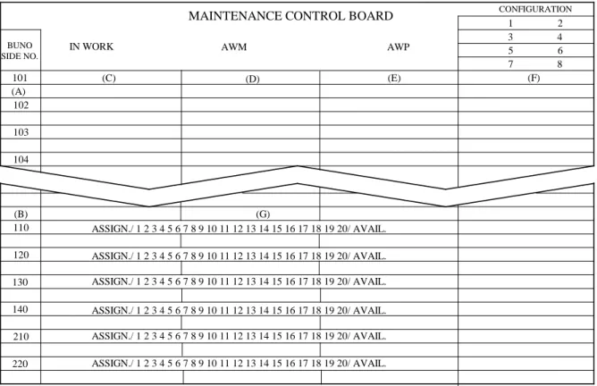
15.1.1.1.2 Maintenance Control VIDS Board (Figures 15-1 through 15-6). This board provides the current
IN WORK, AWM, and AWP status of each aircraft, miscellaneous equipment, for example, aircrew personal
protective equipment and SE, and displays scheduled and unscheduled maintenance including discrepancies,
parts on order, aircraft configuration, current workload, and manning of each work center.
15.1.1.1.3 Items used for operation of the VIDS system, such as signal tabs, file containers, replacement
pockets for the VIDS boards, and three ring binders, may be obtained through the Navy Supply System or
open purchase procurement.
15.1.1.2 General Procedures
15.1.1.2.1 Information Display Requirements. Efficient management of the maintenance effort requires that
certain information concerning the activity's resources be available. The range and depth of information
requirements are determined by such factors as mission, size, and the physical layout of facilities. For
purposes of standardization and to ensure the minimum information requirements are displayed, the
following guidelines will be considered:
a. Number of aircraft assigned.
b. Current aircraft discrepancy status.
c. Aircraft configuration.
d. Aircraft airframe/engine component time.
e. Work center loading.
f. Work center manning.
g. Projected flights.
h. Maintenance requirements.
i. Anticipated board format.
15.1.1.2.2 Prior to actual establishment of the VIDS boards, a determination shall be made about what
method will be used to display types of discrepancies or maintenance actions, for example, by use of color
signal tabs, color fillers within the pockets, NMC or PMC signs, or other methods desired locally.
Depending upon the method chosen, additional pockets may be required to indicate discrepancies which do
not result in NMC or PMC categories. The following display methods are provided for guidance:
a. RED tab, RED filler, NMC tab or sign. Denotes a discrepancy which places the aircraft in an NMC
category.
b. BLUE tab, BLUE filler, PMC tab or sign. Denotes a discrepancy which places the aircraft in a PMC
category.
c. No color tab, no color filler, no NMC or PMC tab or sign. Denotes a discrepancy that does not affect
the NMC or PMC categories.
15.1.1.2.3 Board Setup. It is not mandatory to set up the VIDS boards in the exact formats contained in
Figures 15-1 through
15-6. However, IN WORK, AWM, and AWP status shall be visually displayed by
aircraft bureau/side number and, in the case of nonaircraft related discrepancies, for example, aircrew PPE
and SE, a miscellaneous section will be used and discrepancies will be displayed by work center number or
by TEC and serial number/aircrewman's identification number. A separate board for miscellaneous
equip-of aircraft, activities, or board formats may require more than three pockets. This shall be determined by
each individual activity.
15.1.1.2.4 Maintenance Control will maintain an ADB for each aircraft assigned. The ADB is designed to
provide maintenance and aircrew personnel with an accurate, comprehensive, and chronological record of
flights and maintenance performed on a specific aircraft by BUNO for at least the last 10 flights. All aircrew,
ground crew, and fix phase MESM coded discrepancies, as well as all other outstanding fix phase
discrepancies, shall be displayed in the ADB so the aircrew is fully aware of potential limitations for a safe
and successful mission. For phase or special inspections, only the control document representing all look
phase actions needs to be displayed in the ADB. The ADB shall accurately reflect the status of all pending
maintenance requirements as shown on the Maintenance Control and work center VIDS boards. The ADB
for each specific BUNO shall be validated for completed and outstanding MAFs before certifying the aircraft
Safe for Flight. Paragraph 15.1.1.3 provides procedures for control of the documents in the ADB.
NOTES: 1. When a special inspection is completed, the control document, MAF Copy 3, will be retained in the ADB for 10 subsequent flights or until completion of the next like special inspection. 2. Equipment Discrepancy Books for AMCM equipment will be maintained by the AMCM Systems Maintenance Department Maintenance Control using the instructions for ADBs. 3. Activities using NTCSS Optimized OMA NALCOMIS shall use and upkeep the AADB in the system. Additionally, with the NTCSS Optimized OMA NALCOMIS release 831-01.05.00 or greater, the SA/DBA shall perform a backup of all Aircraft AADB Summary pages in PowerSoft Report (PSR) format on an external media source, for example, floppy disk, CD, or external hard drive. At a minimum, AADB Summary page backups shall be performed prior to the first event of the flight schedule and at the end of each shift. Software to view/print the PSR format files may be loaded on the squadron’s foundation tier server and on the NTCSS OMA NALCOMIS COTS DELTA CD.
15.1.1.3 Operating Procedures
15.1.1.3.1 There are several methods of operating the VIDS system in an O-level maintenance activity, but
only the current discrepancy status display method is described (Figures 15-1 through
15-6). With this
method, it is possible to maintain control of maintenance without requiring extensive communication.
Regardless of the type of display, MAINTENANCE CONTROL MUST BE IN CONTROL OF
MAINTE-NANCE to ensure successful operation. Information shall flow expeditiously among Maintenance Control,
Material Control, and the work center. Each time the status of a discrepancy changes, Maintenance Control
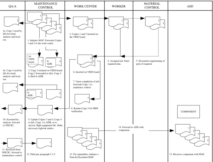
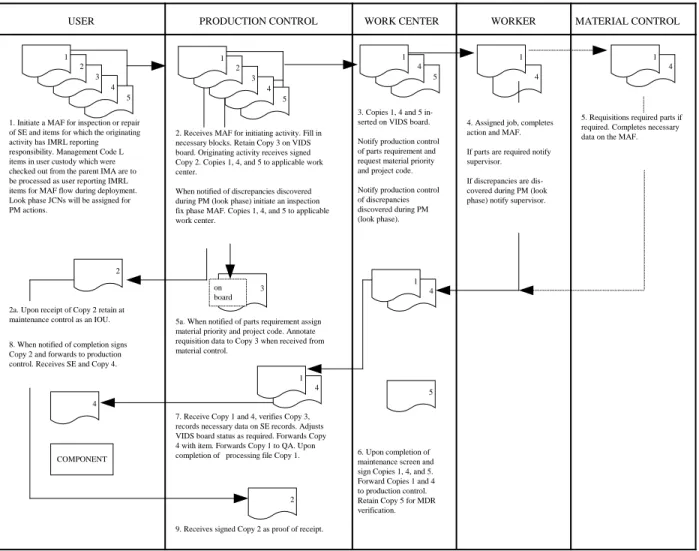
shall be notified immediately. Figure 15-7 contains a flow chart of the VIDS procedures. Figure 15-8 shows
procedures for inducting SE and organizational IMRL items into the IMA/FRC for unscheduled or scheduled
maintenance.
15.1.1.3.2 The Maintenance Control Supervisor will verify the status board with the various work centers at
least daily. The supervisor will then determine which work centers have the capability to handle incoming
discrepancies. Based on that decision, the following phases shall be conducted to ensure efficient operation
and availability of maximum information.
15.1.1.3.2.1 MAF Initiation. Upon completion of the flight, the pilot/aircrew initiates a MAF for each
discrepancy annotating the blocks listed below. For discrepancies discovered by other than pilot or aircrew,
the form will be initiated by the person who discovered the discrepancy. In the case of When Discovered
Code O, Maintenance Control will fill in the blocks listed below.
NOTE: Corrosion Prevention MAF/WOs may be initiated by the pilot, aircrew, or maintenance personnel.
b. PILOT/INITIATOR. The name and rank or rate of the originator of the discrepancy is printed in this
block.
c. RECEIVED-DATE-TIME.
d. BUNO.
e. UP OR DOWN ARROW (circle as applicable to indicate aircraft status).
f. WHEN DISCOVERED CODE.
g. EOC.
NOTE: The specific T/M/S MESM will be used to screen each discrepancy system/subsystem for SCIR applicability and assign the appropriate EOC code. MESM matrices are provided on
COMNAVAIRFOR’s web portal.
15.1.1.3.2.2 Maintenance Control reviews each MAF with the pilot or initiator to ensure the blocks in
paragraph 15.1.1.3.2.1 have been annotated. The following additional blocks are then annotated by
Maintenance Control:
a. TYPE EQUIP.
b. TYPE MAINT.
c. JCN.
d. W/C.
e. QA REQD (applicable only when a QAR is required).
f. C/F REQD (applicable only when a FCF is required).
15.1.1.3.2.3 Maintenance Control completes and reviews the required entries, places MAF Copy 3 in the
applicable VIDS board column, and forwards Copy 2 to QA. Copies 1 and 5 are then sent to the appropriate
work center. Copy 4 is placed on the right side of the ADB where it shall remain as long as the discrepancy
remains outstanding, regardless of the flight to which it applies.
15.1.1.3.2.3.1 When corrective action has been completed, Maintenance Control verifies MAF Copy 1 and
transcribes applicable data to Copies 3 and 4. Copy 3 is then placed on the left side of the ADB where it
shall remain for 10 subsequent flights following the completion date or beneath the Aircrew Personal
Equipment Record (as appropriate). Copy 4 is removed from the right side of the ADB and forwarded to QA
for trend analysis and other local use.
15.1.1.3.2.3.2 When parts or materials are required, the Maintenance Control Supervisor will assign the
appropriate project code and priority designator to Copy 1 of the MAF, and forward the MAF to Material
Control. Refer to DOD 4140.1-R for proper application of priority designators and NAVSUP Publication
485 for project codes.
15.1.1.3.2.3.3 Maintenance Control removes Copy 3 after 10 subsequent flights, when it may be destroyed,
provided a completed Copy 1 has been processed and is in the historical file.
15.1.1.3.3.4 Repair Cycle Documentation:
a. Received Line. The Work Center Supervisor enters, in block B16, the alpha character of the EOC
code that best describes the current mission capability, if applicable. "Received" is automatically considered
to be in a maintenance status.
b. In Work Line. The work center enters the Julian date and time work was begun on the maintenance
action. This date and time shall be equal to or later than the date and time on the "Received" line. The Work
Center Supervisor enters, in block B27, the alpha character of the EOC code, if applicable, that best describes
the mission capability of the aircraft when work began. "In Work" is automatically considered to be in a
maintenance status.
c. Completed Line. The work center enters the Julian date and time the maintenance action was
completed. This date and time shall be the latest date and time entered in the repair cycle. Since the
"Completed" line indicates the end of the maintenance action, it is neither maintenance nor supply and no
EOC code applies.
15.1.1.3.3.5 When notified of an AWP situation by the work center, Maintenance Control shall enter S in the
appropriate job status block and fill in appropriate date, time, and alpha character of the EOC code blocks.
Maintenance Control also fills in the PROJ, PRI, and requisition number blocks in the Failed/Required
Material section and moves the form to the appropriate column on the VIDS board.
15.1.1.3.3.6 When notified of a change from AWP to AWM status, Maintenance Control shall enter an M in
the Maintenance/Supply Record with the Julian date, time of status change, and the alpha character of the
EOC code and move the MAF to the appropriate column on the VIDS board.
15.1.1.3.3.7 When notified of an EOC code change, Maintenance Control shall enter an M in the
Maintenance/Supply Record with the Julian date, time of code change, and applicable alpha character of the
EOC code and move the MAF to the appropriate column on the VIDS board.
15.1.1.3.3.8 In addition to the above, Maintenance Control shall:
a. Maintain current aircraft status on the VIDS board.
b. Maintain current equipment status.
c. Maintain cognizance of all incomplete maintenance actions.
d. Take actions necessary for reporting configuration, material readiness, and flight data.
e. Brief pilots and aircrew prior to an FCF through the use of appropriate QA and work center
personnel (as required) to describe the maintenance performed, the requirements for that particular flight, and
the expected results.
f. Monitor SCIR data repair cycle and maintenance/supply record on MAF Copies 3 and 4.
g. Comply with all maintenance documentation actions assigned to Maintenance Control in paragraph
15.2.
15.1.1.4 Phase Maintenance Procedures
15.1.1.4.1 When an aircraft is inducted into a phase inspection, Maintenance Control and the inspection
supervisor shall remove all the MAFs, except the inspection control document, from the Maintenance Control
VIDS board, and place them on the inspection work center's VIDS board. Activities using an individual
VIDS board for each aircraft may issue the Maintenance Control VIDS board to the inspection Work Center
Supervisor in lieu of removing and replacing MAFs.
15.1.1.4.2 When Maintenance Control is notified that the inspection has been completed, it will return the
MAF registers to the appropriate columns of the Maintenance Control VIDS board and indicate if an FCF is
required.
15.1.1.4.3 All cannibalization actions shall be authorized and directed by Maintenance Control.
15.1.1.5 Historical Files
15.1.1.5.1 Completed and processed MAF Copy 1s are to be retained by Maintenance Control for a
minimum of 6 months from the completed date, block B30.
15.1.1.5.2 Historical file requirements are as follows:
a. Aircraft Inspection File. This file is maintained for each BUNO and should be arranged to group the
control, look, and fix phase documents for a given inspection. Documents in support of a phased or special
inspection will be retained for one complete inspection cycle or 6 months, whichever is greater. Conditional
inspection documents will be maintained in this file for a minimum of 6 months from the completion date.
b. Aircraft General File. This file will be maintained by BUNO in JCN sequence and grouped by
month of completion (block B30). Individual units have the option of establishing local files by work center
as long as the above filing order is maintained. Contents will include all other aircraft and engine MAFs.
MAFs that are SCIR related with Action Taken Code N will be retained for a minimum of 6 months from the
completed date.
c. TD Compliance File. This file will be maintained by BUNO for a minimum of 6 months from the
completed date (block B30).
NOTE: Upon aircraft transfer, ensure the aircraft inspection, TD compliance, and general files are forwarded with the aircraft.
d. Miscellaneous File. This file will contain all non-BUNO MAFs and may be separated by TEC, SER,
or JCN, as decided by the local command.
e. Aircrewman's Flight Equipment File. Each aircrewman shall have a separate file containing the
Aircrew Personal Equipment Record and required Aircrew Systems Records. Completed MAF Copy 1 for
all maintenance performed on this equipment shall be retained in this file for 6 months per this instruction.
f. SE File. Completed MAFs Copy 1 shall be filed by Maintenance Control for a minimum of 6
months from the completed date (Block B30). Documents in support of PM inspections will be maintained
for 6 months or one complete inspection cycle whichever is greater. This file will be arranged in sequence of
equipment nomenclature, serial number, and JCN, that is, JCN within serial number within nomenclature.
These files and all outstanding discrepancy MAFs shall accompany SE that is transferred or temporarily
loaned to another activity.
15.1.1.6 Naval Flight Record Subsystem (NAVFLIRS)
15.1.1.6.1 NAVFLIRS provides a standardized Department of the Navy flight activity data collection
system. The Naval Aircraft Flight Record (OPNAV 3710/4) consists of an original and two no carbon
required copies. All three copies contain identical information. Procedures for filling out the form are
outlined in OPNAVINST 3710.7.
15.1.1.6.2 Procedures for processing completed Naval Aircraft Flight Records by Maintenance Control are
as follows:
a. Navy Procedures. A Naval Aircraft Flight Record is required for each attempt at flight. The aircraft
or mission commander's signature certifies completeness and accuracy of the form. Maintenance Control
screens the Naval Aircraft Flight Record and transcribes applicable data into aircraft logbooks. Operations
Department personnel will screen it and transcribe information into aviator logbooks. Ensuring the validity
of NAVFLIRS data requires complete coordination between the analyst, Maintenance Control, and the
Operations Department.
b. Marine Corps Procedures. A Naval Aircraft Flight Record is required for each attempt at flight. The
aircraft or mission commander signs it, certifying completeness and accuracy. The operations duty officer
screens the Naval Aircraft Flight Record for completeness and accuracy and passes it to operations personnel.
The Naval Aircraft Flight Record is screened by operations personnel and separated. Operations Department
personnel will screen it and transcribe information into aviator logbooks. Ensuring the validity of
NAVFLIRS data requires coordination between Maintenance Control and the Operations Department.
15.1.1.7 MAF Work Request
15.1.1.7.1 This form is used by supported maintenance and supply activities to request work or assistance
from the I-level that is beyond the requesting activity's capability and does not involve repair of aeronautical
material. The MAF work request is prepared and processed per Chapter 16.
15.1.1.7.2 The MAF work request is used primarily for, but not limited to:
a. Request check, test, and service of items removed from an aircraft, equipment, or SE for scheduled
maintenance when requested work is beyond the capability of the requesting activity.
NOTE: Work requests for items removed for check, test, service, and local manufacture or fabrication shall be approved and signed by the requesting activity's Maintenance Control Supervisor and the supporting activity's Production Control Supervisor. Batteries removed for check, test, or service will be documented per paragraph 15.2.
b. Induct items that are not part of an aircraft or SE, for example, pilot's personal equipment, oxygen
masks, life preservers, and parachutes, that require check, test, and service.
c. Induct items from Supply for check, test, and service.
d. Induct items from Supply for buildup, such as engines, QECKs, and wheel and tire assemblies that
are beyond the supply activity's capability.
e. Induct items not having a WUC or not identifiable to a specific type of equipment for check, test, and
service or for local manufacture or fabrication.
f. Request NDI either on-site or at I-level, when a TD is not involved.
g. Induct items for ready for issue certification prior to reinstallation in aircraft returned from SDLM.
15.1.1.8 Maintenance Division Officers
It is incumbent upon all division officers to have thorough familiarity with machine reports concerning the
division and to be capable of interpreting these reports. Chapter 14 contains descriptions of these reports.
R}
15.1.2 Maintenance Control Operating NALCOMIS
a. The function of management has been defined as the "efficient attainment of enterprise objectives".
Maintenance has been defined as "all actions taken to retain material in a serviceable condition or to restore it
to serviceability". When these are combined, we can define maintenance management as "the actions
necessary to retain in or restore material or equipment to a serviceable condition with an optimum
expenditure of resources".
b. It is the responsibility of all maintenance managers to manage their resources in an efficient manner.
To accomplish this task they shall maintain control of the various elements within their area of responsibility.
Effective control is dependent upon the availability of current status information on these elements.
NALCOMIS provides this information.
c. NALCOMIS significantly reduces the administrative burden and produces up-to-date status
information necessary for the control of maintenance. Communication between Maintenance Control, work
centers, and Material Control is essential to ensure successful operation. Each time a change of job status
occurs, for example, from in work to awaiting maintenance, and from in work to awaiting parts, Maintenance
Control shall be notified and NALCOMIS updated immediately by the Work Center Supervisor.
d. The maintenance manager is concerned with aircraft status, operational commitments, aircrew
personal protective equipment status, SE status, workload requirements, and personnel assets. Efficient
operation requires a centralized control point through which all information concerning these areas must pass.
In an O-level activity this central point is Maintenance Control.
(1) The MMCO shall be responsible for the overall management of the maintenance effort. This
responsibility is exercised primarily through the various Maintenance Division officers/supervisors.
(2) Maintenance Division officers shall be responsible for the actual productive effort within their
divisions. They shall keep the MMCO informed of any problems that can affect the department's/division's
output.
(3) NALCOMIS is a management tool that provides vital, realtime information on a continuing
basis through online visual display and reports. The system correlates all aircraft status information,
particularly NMCS/PMCS, flyable discrepancies, nonaircraft related discrepancies, for example, aircrew
personal protective equipment and SE, and assigns a relative importance to each item. The ability to review
the overall situation and determine what resources are available enables the MO and MMCO, or supervisor,
to carry out their duties more effectively and efficiently.
NOTE: Commands using NTCSS Optimized OMA NALCOMIS will refer to the NTCSS Optimized OMA NALCOMIS SA Manual for aircraft mishap procedures.
15.1.2.1 Hardware
15.1.2.1.1 NALCOMIS consists of a host computer linked to workstations by a LAN. This allows
maintenance managers to enter data and obtain standardized information in support of the maintenance effort.
15.1.2.1.2 Items used for the operation of NALCOMIS, for example, paper and printer ribbons, may be
obtained via the Navy Supply System/open purchase.
15.1.2.2 General Features
15.1.2.2.1 General features of NALCOMIS OMA consist of functions to enter, collect, process, store,
review, report, and interface data required by the O-level. Additional features include:
a. Logins. Upon successfully connecting to NALCOMIS OMA, the user login and password shall be
entered to identify and authenticate the user to the system. The unique user login and password will be
validated against the database by the operating system. All security relevant actions taken for example,
system logon, logoff, and data file access may be recorded in the audit trail.
b. Screens. NALCOMIS OMA screens consist of several major sections: headings,
informa-tion/questions, data, display message, function keys, and status. On screen help is provided throughout the
system.
c. Query. The query options allow all users the ability to view data in the major subsystems, MAF
queries, flight queries, logs and records queries, and asset queries.
d. Reports. NALCOMIS OMA provides the ability to print several formatted reports. The reports
cover all the major subsystems, for example, maintenance, flight, and logs and records.
e. Ad hoc. This utility allows users the ability to create reports to their specific needs, for example,
trend analysis and work center manpower utilization.
15.1.2.2.2 NALCOMIS Reports. Reports are the primary management tool. Maintenance managers, such as
Maintenance Control Supervisors and Work Center Supervisors, will manage their maintenance efforts using
various reports. Most commonly used are the Aircraft/Equipment Work Load Report (Figure 15-9) and
Work Center Work Load Report (Figure 15-10) which provide the following information: work center, TEC,
MODEX, BUNO, MCN, JCN, A/C Equip status, job status, EOC, WUC, system reason, DDSN, project
code, supply status, date received, and totals at end of report.
15.1.2.2.3 ADB. Maintenance Control will maintain an ADB for each aircraft assigned. The ADB is
designed to provide maintenance and aircrew personnel with an accurate, comprehensive, and chronological
record of flights and maintenance performed on a specific aircraft by BUNO for at least the last 10 flights.
All aircrew, ground crew, and fix phase MESM coded discrepancies, as well as all other outstanding fix
phase discrepancies, shall be displayed in the ADB so the aircrew is fully aware of potential limitations for a
safe and successful mission. For phase or special inspections, only the control document representing all
look phase actions needs to be displayed in the ADB. The ADB shall accurately reflect the status of all
pending maintenance requirements as displayed in the NALCOMIS database, the Maintenance Control
Supervisor will verify the ADBs with NALCOMIS at least daily. The ADB for each specific BUNO shall be
screened for accuracy of completed and outstanding MAFs before Maintenance Control certifies the aircraft
Safe for Flight.
NOTES: 1. When a special inspection is completed, the control document will be retained in the ADB for 10 subsequent flights or until completion of the next like special inspection.
2. Equipment Discrepancy Books for AMCM equipment will be maintained by the AMCM Systems Maintenance Department Maintenance Control using the instructions for ADBs. 3. Activities using NTCSS Optimized OMA NALCOMIS shall use and upkeep the AADB in the system. Additionally, with the NTCSS Optimized OMA NALCOMIS release 831-01.05.00 or greater, the SA/DBA shall perform a backup of all Aircraft AADB Summary pages in R} MDI format on an external media source, for example, floppy disk, CD, or external hard drive. At a minimum, AADB summary page backups shall be performed prior to the first event of the flight schedule and at the end of each shift. Refer to https://webnet.scn.spawar.navy.mil FAQ section
or COMNAVAIRFOR’s web portal for instructions on how to save AADB Summary pages
15.1.2.3 Operating Procedures
15.1.2.3.1 MAINTENANCE CONTROL MUST BE IN CONTROL OF MAINTENANCE to ensure
successful operation. Information shall flow expeditiously among Maintenance Control, Material Control,
and the work center. Each time the status of a discrepancy changes, Maintenance Control shall be notified
immediately.
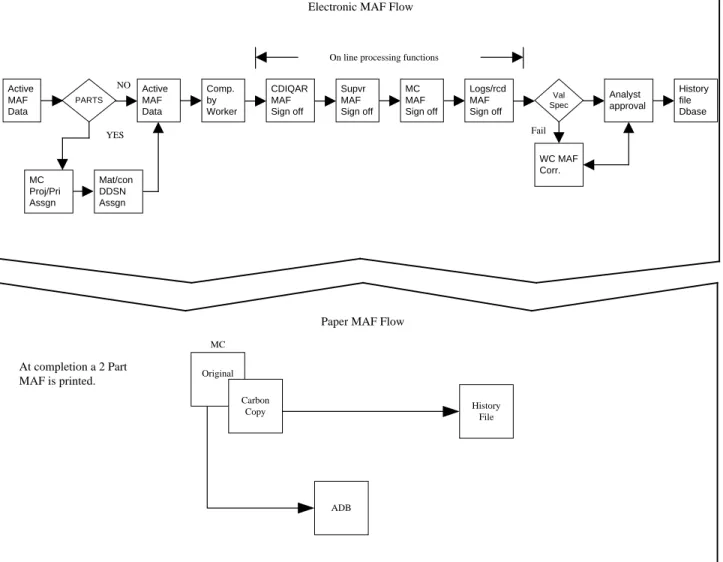
15.1.2.3.2 Figures 15-11 and 15-12 contain flow charts of NALCOMIS MAF procedures. The Maintenance
Control Supervisor will determine which work centers have the capability to handle incoming discrepancies.
Based on that decision, the following phases shall be conducted to ensure efficient operation and availability
of maximum information.
15.1.2.3.2.1 MAF Initiation. Upon completion of the flight, the pilot/aircrew initiates a MAF for each
dis-crepancy. For discrepancies discovered by other than pilot or aircrew, the MAF will be initiated by the
person who discovered the discrepancy. In the case of When Discovered Code O, Maintenance Control will
initiate the MAF. Corrosion Prevention MAF/WOs may be initiated by any pilot, aircrew, or maintenance
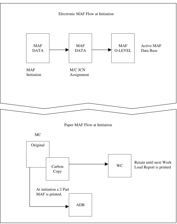
personnel. NALCOMIS prompts the user for required data fields during MAF initiation. The JCN is
automatically assigned when the MAF is approved. The Type MAF Code, TEC, BUNO, T/M, MODEX,
received date, and received time are pre-filled. The received date and time can be changed. Work center,
discrepancy, initiator, and up/down status field shall be filled in prior to saving to the database. Maintenance
Control will use the applicable MESM to screen each discrepancy for impact on the affected aircraft
system/subsystem. A MESM is essential to perform specific missions and achieve required material
condition readiness, maintenance standards, supply system effectiveness, and safety requirements of
OPNAVINST 3710.7. All other fields are optional.
NOTE: If the status is SCIR impacted, the correct WUC/UNS must be entered and the appropriate EOC code assigned. MESM matrices are provided on COMNAVAIRFOR’s web portal.
15.1.2.3.2.2 Maintenance Control awaiting JCN assignment. Upon reviewing MAFs, Maintenance Control
has the option to modify all fields of the MAF. Upon MAF approval, the MAF is ready to be printed.
15.1.2.3.2.3 Maintenance Control prints a two part MAF. Once the MAF is printed the original copy is
placed on the right side of the ADB and shall remain as long as the discrepancy remains outstanding. A
carbon copy is routed to the appropriate work center. Work centers shall retain the carbon copy until it
appears on the next Work Center Work Load Report.
15.1.2.3.2.3.1 When corrective action has been completed, Maintenance Control reviews, approves, or
rejects MAFs. Upon approval of MAF completion, Maintenance Control prints a two-part MAF. The
original completed copy is then placed on the left side of the ADB where it shall remain for 10 subsequent
flights following the completion date. The outstanding copy is removed from the right side of the ADB and
discarded. The completed carbon copy is retained for historical files.
15.1.2.3.2.3.2 When parts or materials are required, the Maintenance Control Supervisor will enter the
appropriate project code and priority designator on the MAF, using the project/priority assignment online
process. The MAF is electronically forwarded to Material Control's DDSN assignment online process. Refer
to DOD 4140.1-R for proper application of priority designators and NAVSUP Publication 485 for project
codes.
15.1.2.3.2.3.3 Flights shall be separated by the Aircraft Inspection and Acceptance Record (CNAF 4790/
141). Use of this form is described in this instruction.
15.1.2.3.3.1 Received Line. The Work Center Supervisor enters the alpha character of the EOC code that
best describes the current mission capability (if applicable) in job status update. "Received" is automatically
considered to be in a maintenance status. The Work Center Supervisor has the capability to modify entered
data.
15.1.2.3.3.2 In Work Line. The work center enters the job status in the job status update and has the
capability to modify pre-filled date/time. The work center enters the alpha character of the EOC code (if
applicable) that best describes the mission capability of the aircraft when work began. "In Work" is
automatically considered to be in a maintenance status.
15.1.2.3.3.3 Completed Line. The job status code of JC is automatically applied when the work center enters
the completed date/time and "Corrected By" (electronic) signature. This date and time can not be modified
without reinducting the MAF. Since the "completed" line indicates the end of the maintenance action, it is
neither Maintenance nor Supply status related and no EOC code applies.
15.1.2.3.3.4 When the MAF is placed in job status WP by Material Control, Material Control shall enter S in
the Maintenance/Supply Record and fill in the appropriate date and time. The Work Center Supervisor shall
ensure the appropriate EOC code is entered in the Maintenance/Supply Record.
15.1.2.3.3.5 When the MAF is changed from WP to M (series) status by Material Control, Material Control
shall enter an M in the Maintenance/Supply Record with the Julian date and time of status change. The Work
Center Supervisor shall ensure the appropriate EOC code is entered in the Maintenance/Supply Record.
15.1.2.3.3.6 Maintenance Control shall:
a. Maintain current aircraft status within NALCOMIS.
b. Maintain current equipment status.
c. Maintain cognizance of all incomplete maintenance actions.
d. Take actions necessary for reporting configuration, material readiness, and flight data.
e. Brief pilots and aircrew prior to an FCF through the use of appropriate QA and work center
personnel (as required) to describe the maintenance performed, the requirements for that particular flight, and
the expected results.
f. Monitor SCIR data repair cycle and maintenance/supply records on the MAF.
g. Comply with all maintenance documentation actions assigned to Maintenance Control (paragraph
15.2).
h. Review all end of month close out candidates and annotate new MCN in the ADB or replace existing
MAF in ADB with the reinitiated MAF, and assist the analyst as required in performing SCIR end of month
close out actions.
i. Full systems and database backups are a major requirement of operating NALCOMIS OMA.
Backups and restores shall be accomplished on a regular basis per OMA-SAM.
15.1.2.4 Phase Maintenance Procedures
15.1.2.4.1 When an aircraft is inducted into a phase inspection, Maintenance Control and the inspection
supervisor shall ensure all MAFs are properly documented into NALCOMIS, for example, work center
change, FCF compliance, and QA required.
15.1.2.4.2 All cannibalization actions shall be authorized and directed by Maintenance Control.
15.1.2.5 Historical Files
15.1.2.5.1 NALCOMIS activities will store completed MAF data in the NALCOMIS OMA database for a
minimum of 6 months from completion date, and documents in support of a phased or special inspections
will be stored for one complete inspection cycle or 6 months, whichever is greater. NALCOMIS allows
activities the option of storing up to forty-eight months of historical MAFs in the NALCOMIS database.
Activities implementing NALCOMIS shall retain paper historical MAF files until the NALCOMIS database
contains the required historical MAF files.
15.1.2.5.2 Historical file requirements for activities using paper MAFs are as follows:
a. Aircraft Inspection File. This file is maintained for each BUNO and should be arranged to group the
control, look, and fix phase documents for a given inspection. Documents in support of a phased or special
inspections will be retained for one complete inspection cycle or 6 months, whichever is greater. Conditional
inspection documents will be maintained in this file for a minimum of 6 months from the completion date.
b. Aircraft General File. This file will be maintained by BUNO in JCN sequence and grouped by
month of completion (block B30). Individual units have the option of establishing local files by work center
as long as the above filing order is maintained. Contents will include all other aircraft and engine MAFs.
c. TD Compliance File. This file will be maintained by BUNO for a minimum of 6 months from the
completed date (block B30).
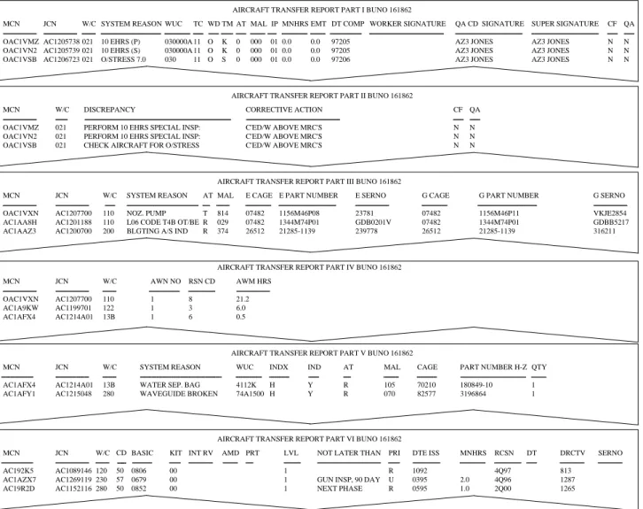
NOTES: 1. Upon aircraft transfer, ensure the aircraft inspection, TD compliance, general files, and electronic history data/ALS are forwarded with the aircraft or to the OOMA Electronic Repository (as applicable) per this instruction.
2. Any time a NALCOMIS OMA transfers an aircraft to a non-NALCOMIS activity, the transferring activity shall produce a NALCOMIS OMA ad hoc Aircraft Transfer Report (Figure 15-13) and send it to the receiving activity. Refer to the OMA-SAM for specific procedures when transferring an aircraft to another NALCOMIS OMA.
d. Miscellaneous File. This file will contain all non-BUNO MAFs and may be separated by TEC, SER,
or JCN, as decided by the local command.
e. Aircrewman's Flight Equipment File. Each aircrewman shall have a separate file containing the
Aircrew Personal Equipment Record and required Aircrew Systems Records. Completed MAF Copy 1 for
all maintenance performed on this equipment shall be retained in this file for 6 months per this instruction.
15.1.2.6 Naval Flight Record Subsystem (NAVFLIRS)
15.1.2.6.1 NAVFLIRS provides a standardized Department of the Navy flight activity data collection
system. NALCOMIS automates the Naval Aircraft Flight Record (OPNAV 3710/4) and provides a single
copy form. Procedures for filling out the form are outlined in OPNAVINST 3710.7.
15.1.2.6.2 A Naval Aircraft Flight Record is required for each attempt at flight. The aircraft or mission
commander's signature certifies completeness and accuracy of the form. Maintenance Control screens the
Naval Aircraft Flight Record and transcribes applicable data into aircraft logbooks. The NAVFLIRS will be
forwarded to the analyst, via logs and records. Upon receipt of the NAVFLIRS, the analyst will submit it to
operations to transcribe into aviators logbooks. Ensuring the validity of NAVFLIRS data requires complete
coordination between the analyst and the Operations Department.
15.1.2.7 MAF Work Request
15.1.2.7.1 This MAF work request is used by supported maintenance and supply activities to request work or
assistance from the IMA/FRC that is beyond the requesting activity's capability and does not involve repair
of aeronautical material. The MAF work request is prepared and processed per Chapter 16.
15.1.2.7.2 The MAF work request is used primarily for, but not limited to:
a. Request check, test, and service of items removed from an aircraft, equipment, or SE for scheduled
maintenance when requested work is beyond the capability of the requesting activity.
NOTE: Work requests for items removed for check, test, service, and local manufacture or fabrication shall be approved and signed by the requesting activity's MaintenanceControl Supervisor and the supporting activity's Production Control Supervisor. Batteries removed for check, test, or service will be documented per paragraph 15.2.