Installation Guidelines
NWFA Information Available
as of
CONTENTS
SECTION
I
–
GENERAL
GUIDELINES
CHAPTER 1 JOBSITE CONDITIONS
CHAPTER 2 ACCLIMATION
CHAPTER 3 MOISTURE REQUIREMENTS AND MOISTURE TESTING
SECTION II – SUBFLOOR GUIDELINES & SPECIFICATIONS
CHAPTER 4 WOOD SUBFLOOR GUIDELINES
CHAPTER 5 CONCRETE SUBFLOOR GUIDELINES CHAPTER 6 INSTALLING A SUBFLOOR OVER CONCRETE
SECTION III – INSTALLATION GUIDELINES
&
METHODS
CHAPTER 7 PARQUET INSTALLATION
CHAPTER 8 ENGINEERED FLOORING INSTALLATION CHAPTER 9 SOLID STRIP & PLANK INSTALLATION CHAPTER 10 INSTALLING OVER AN EXISTING FLOOR
SECTION
IV
APPENDICES
Appendix A SAFETY GUIDELINES
Appendix B ACCLIMATION
Appendix C MOISTURE GUIDELINES & MOISTURE TESTING Appendix D MOISTURE BY AREA – US
Appendix E MOISTURE BY AREA – CANADA
Appendix F FASTENER SCHEDULE
Appendix G TRAMMEL POINT METHOD
Appendix H RADIANT HEAT INSTALLATIONS Appendix I INSTALLATION OVER SCREEDS
Appendix J SOUND CONTROL
Appendix K TRIM & THRESHOLDS Appendix L SAMPLE SPECIFICATION Appendix M JOBSITE CHECKLIST
SECTION V
GLOSSARY
GLOSSARY OF WOOD FLOORING TERMS
Copyright 2007 National Wood Flooring Association Revised March 2007
SECTION I
GENERAL GUIDELINES
CHAPTER 1
JOBSITE CONDITIONS...Page 1
CHAPTER 2
ACCLIMATION ...Page 5
CHAPTER 3
MOISTURE REQUIREMENTS
Chapter 1 – Jobsite Conditions
CHAPTER 1
JOBSITE CONDITIONS
Part I – Minimum Jobsite Requirements
A. Wood flooring should be one of the last jobs completed on the construction project. Limit foot traffic on finished wood flooring.
B. Evaluate the jobsite for potential problems before installation begins, and before wood flooring is delivered to the jobsite.
C. Unless a waiver or letter of protest listing exceptions exists, installation constitutes
acceptance of subfloor/substrate, the jobsite itself – including the ambient temperature and relative humidity at the time of installation, and all impacting variables that may affect a wood floor.
1. Surface drainage should direct water away from the building.
2. Do not deliver wood flooring to the jobsite or install wood flooring until the building is enclosed.
3. If heating and/or air-conditioning is in operating condition, it needs to be operating. If it is not possible for the permanent heating and/or air-conditioning system to be operating before, during and after installation, a temporary heating and/or dehumidification system that mimics normal temperature and humidity conditions can enable the installation to proceed until the permanent heating and/or air-conditioning system is operating.
4. Do not deliver wood flooring to the jobsite or install wood flooring until appropriate temperature and humidity conditions have been achieved. Appropriate temperature and humidity conditions are defined as those conditions to be experienced in the building after occupancy.
5. Do not deliver wood flooring to the jobsite or install wood flooring until all concrete, masonry, plastering, drywall, texturing and painting primer coats are completed.
6. Basements and crawl spaces must be dry. If power washing is required in the basement, do so before wood flooring is installed and allow subfloor and basement to dry before installing wood flooring.
7. Crawl space should be a minimum of 18” (457mm) from ground to underside of joists. 8. Crawl space earth (or thin concrete slab) should be covered 100 percent by a vapor
retarder of black polyethylene (minimum 6 mil) or any recommended puncture-resistant membrane, such as Class C, meeting ASTM D-1745. See Figure 1-1.
Chapter 1 – Jobsite Conditions
9. Crawl Space Conditions a. Where a proper ground
covering is in place and when venting is
required by local building codes, the crawl space should have perimeter venting equal to a minimum of 1.5 square feet per 100 square feet of crawl space square footage, unless local building codes differ from this specification. Note:
Local-building codes may differ. Follow local building codes.
Figure 1-1
b. For crawl spaces without ventilation openings, vapor retarder joints must overlap a minimum of 6 inches and be sealed or taped. The vapor retarder should also extend at least 6 inches up the stem wall and be attached and sealed to the stem wall. Continuously operated mechanical exhaust and perimeter wall insulation or conditioned air supply and insulation must be provided.
10. Note the grade level so that the correct type of flooring and system can be specified for the job. Engineered and floating floors can be appropriate for above-grade, on-grade and below-grade installations. Solid wood flooring can be appropriate for above-grade and on-grade installations, but not for below-grade installations. If the soil
surrounding a structure is 3 inches or more above the floor of any level, consider that level below grade. This includes walk-out basements. In addition, the surrounding soil should be sloped away from the structure. See Figure 1-2.
11. Subfloors (wood or concrete) should be checked by an appropriate method for establishing moisture content. Average subfloor moisture content should be
within the range as specified for the product by the product manufacturer. See Chapter 3, Moisture Testing.
Figure 1-2
Grade Levels
If the soil surrounding a structure is 3 inches or more above the floor of any level, consider that level below grade. This includes walk-out basements. In addition, the surrounding soil should be slo
12. Where the minimum jobsite conditions are present, the flooring can be delivered and stored in the rooms in which it will be installed. See Chapter 2, Acclimation.
ped away from the structure.
Chapter 1 – Jobsite Conditions
Part II - Additional Jobsite Conditions for Factory-Finished Flooring
A. All finished wall coverings and painting should be completed. Note: Base and shoe mold may be installed and finished after the flooring installation.
B. After installation, if you choose to protectively cover the floor, cover the floor completely, since some species are light-sensitive and uncovered areas may change color. However, covering a glue-down application may not allow some adhesives to properly cure. Follow the flooring and adhesive manufacturer’s recommendations. Use a covering material with a vapor permeance (perm rating) of 1 perm or more (tested I accordance with ASTM E-96) to avoid trapping moisture/vapor on or within the floor. A common reinforced builder’s paper is a good choice. Any covering should be taped, using a low-adhesion tape, to base or shoe moldings. Avoid taping to finished flooring. When taping paper or sheets together, tape them to each other, not to the floor.
Part III – Jobsite Checklist
See Appendix MChapter 2 – Acclimation
CHAPTER 2
ACCLIMATION
ALWAYS FOLLOW THE MANUFACTURERS’ RECOMMENDATIONS
REGARDING HOW AND WHETHER TO ACCLIMATE WOOD FLOORING.
Part I – General Acclimation Guidelines
(For a more detailed discussion of acclimation issues, See Appendix B.)
A. Storage and Conditions
1. Do not store wood flooring at the jobsite under uncontrolled climate conditions. Garages and exterior patios, for example, are not acceptable areas to store wood flooring. 2. Ideal interior climate conditions vary from region to region and jobsite to jobsite. It is your
responsibility to know what your “ideal” climate conditions are and build your floor around those conditions. For a general view of moisture-content averages by region, refer to Appendix D and Appendix E.
B. Acclimation
Note: Some manufacturers do not require acclimation for certain products prior to installation. If the manufacturer recommends that the wood flooring be acclimated before installation, proceed as follows:
1. Ensure that the building is enclosed.
2. Verify that the building is maintained at normal living conditions for temperature and humidity.
3. Where building codes allow, permanent heating and/or air-conditioning systems should be operating at least five days preceding installation to promote proper acclimation. For radiant heat see Appendix H.
4. If it is not possible for the permanent heating and/or air-conditioning system to be operating before, during and after installation, a temporary heating and/or
dehumidification system that mimics normal temperature and humidity conditions can enable the installation to proceed until the permanent heating and/or air-conditioning system is operating.
5. Upon delivery, check wood flooring moisture content with a moisture meter to establish a baseline for required acclimation. Check the moisture content of multiple boards. A good representative sample is typically 40 boards for every 1,000 square feet of flooring. Acclimate to manufacturer’s recommendations or as necessary according to geographical location and your jobsite location.
Chapter 2 – Acclimation
6. Prior to installation, ensure that wood flooring is within acceptable range of moisture content with the wood subfloor. For solid strip flooring (less than 3” wide), there should be no more than 4 percent moisture content difference between properly acclimated wood flooring and subflooring materials. For wide-width solid flooring (3” or wider), there should be no more than 2 percent difference in moisture content between properly acclimated wood flooring and subflooring materials.
Chapter 3 – Moisture Testing
7
CHAPTER 3
MOISTURE TESTING
Part I - Moisture Testing for Wood Subfloors
A. Testing Requirements
1. Test for moisture at several locations in the room — a minimum of 20 per 1,000 square feet — and average the results. A high reading in one area indicates a problem that must be corrected. Pay special attention to exterior and plumbing walls
Part II - Acceptable Vapor Retarders Over Wood Subfloors
A. ALWAYS FOLLOW LOCAL CODES AND MANUFACTURERS INSTRUCTIONS FOR ACCEPTABLE VAPOR RETARDERS.
B. An acceptable vapor retarder is a vapor resistant material, membrane or covering with a vapor permeance (perm rating) of greater than or equal to .7 and less than or equal to 50 when tested in accordance with ASTM E-96 Method A. Installation of a vapor retarder reduces the potential for moisture or vapor related problems, but does not guarantee elimination of moisture or vapor related problems. Install a vapor retarder over wood panel or board sub-floors prior to installing nail down solid strip or plank flooring. Over-lap seams a minimum of 4 inches or more as required by manufacturer or specifier and local building codes.
C. Some examples of acceptable vapor retarders over wood subfloors include: 1. An asphalt laminated paper meeting UU-B-790a, Grade B, Type I, Style 1a.
2. Asphalt-saturated kraft paper or #15 or #30 felt paper meeting ASTM Standard D-4869 or UU-B-790, Grade D.
D. NOTE:
1. A vapor retarder has some extra benefits in that it eliminates wood-on-wood contact, wood strips slide more easily when positioned, minimizes the impact of seasonal humidity change and may reduce dust and noise levels.
2. However, by today’s standards, asphalt saturated kraft or felt paper may not be an effective vapor retarder in all applications. The 2006 International Residential Code requires a vapor retarder on the warm-in-winter side of exterior floors (a floor over a vented crawl space, for example), with a vapor permeance of 1 perm or less in Zones 5 and higher.
3. Over a wood subfloor, do not use an impermeable vapor retarder material with a perm rating of .7 or less, such as 6 mil polyethylene film or other polymer materials, as it may trap moisture on or in the wood subfloor.
4. Do not use common red rosin or building paper which is not asphalt saturated. They are not vapor retarders as their perm rating is far greater than 50.
Chapter 3 – Moisture Testing
8
Part III - Moisture Testing for Concrete Slabs
NOTE: All tests give a result – at the time the test is done. And in general give you the ability to start or not start a job – these tests do not give a permanent condition of your substrate merely a “at the time the test was performed” indication.
A. Testing Requirements
1. Before moisture testing begins, the concrete slab must be a MINIMUM of 30 days old. B. Qualitative Moisture Tests
1. Electrical Impedance Test and Electrical Resistance Test (Moisture Meter)
Follow meter manufacturer’s instructions.
a. Use moisture meters designed specifically for concrete moisture testing. b. Test within the body of the slab (electrical resistance), as well as at the surface
(electrical impedance).
c. These testing methods are not recognized by any standard and should not be used for the purpose of accepting or rejecting a floor. These electronic tests are useful survey tools to broadly evaluate the relative moisture conditions of a slab and to select locations for quantitative moisture tests.
d. If the moisture meters indicate the presence of excessive moisture, as per wood flooring or meter manufacturer’s recommendations, further testing is required using relative-humidity testing (ASTM F-2170), calcium chloride testing (ASTM F-1869) or calcium carbide (CM) testing (ASTM D-4944-04 and MilSpec CRD-C154-77). 2. Phenolphthalein Test
a. Perform one test per 200 square feet of surface area, with a minimum of two tests per jobsite.
b. Chip a small section of concrete off the floor and apply 3 percent phenolphthalein in alcohol solution (available at most druggists) in the area. A red color indicates that moisture is present. Always chip the concrete as this protects against the possibility that a concrete sealer was applied.
IMPORTANT: Keep phenolphthalein out of direct sunlight. The average shelf life of phenolphthalein is six months.
c. If the phenolphthalein test indicates the presence of excessive moisture, further testing is required using relative-humidity testing (ASTM F-2170), calcium chloride testing (ASTM F-1869) or calcium carbide (CM) testing (ASTM D-4944-04 and MilSpec CRD-C154-77).
C. Quantitative Moisture Tests
1. Relative Humidity Testing – ASTM F-2170 (Standard Test Method for Determining Relative Humidity in Concrete Floor Slabs Using In Situ Probes)
Chapter 3 – Moisture Testing
9
a. Select test locations to provide information about moisture distribution across the entire concrete floor slab. For slabs on grade and below grade, include a test location within three feet of each exterior wall.
b. Perform three tests for the first 1,000 sq ft and one test for every additional 1,000 sq ft thereafter.
c. At least 48 hours before test is placed, concrete floor slabs should be at the same temperature and humidity that is expected during service conditions.
d. Use a rotary hammer-drill to drill holes in the concrete slab; 40% depth of slab is required for the holes when concrete is drying from one side and 20% when drying from both sides. Follow manufacturer’s instructions provided with test kits. e. Allow 72 hours to achieve moisture equilibrium within the hole before making relative
humidity measurements.
f. ASTM F-710 provides installation guidelines for acceptance of hardwood flooring using relative-humidity testing. Typical limits for wood and wood-based products are 75% relative humidity. When getting readings over 75%, you must use a proper vapor retarder, based on the flooring manufacturer’s recommendations, or wait for further concrete curing.
2. Calcium Chloride Test – ASTM F-1869 (Test Method for Measuring Moisture Vapor Emission Rate of Concrete Subfloor Using Anhydrous Calcium Chloride)
a. Select test locations to provide information about moisture distribution across the entire concrete floor slab.
b. Perform three tests per 1,000 square feet of surface area. Add one additional test for each 1000 square feet thereafter.
c. At least 48 hours before test is placed, concrete floor slabs should be at the same temperature and humidity expected during service conditions
d. The actual test area shall be clean and free of all foreign substances. Use approved OSHA work practices for removal of all existing flooring materials and debris. e. Blast or grind a minimum area of 20 inches by 20 inches and let stand for a minimum
period of 24 hours prior to setting test.
f. Follow manufacturer’s instructions for properly placing tests onto concrete.
g. Tests are to be covered and left in place for 60 to 72 hours. Follow manufacturer’s instructions for labeling and recording time and date of test.
h. Send the test to a certified laboratory for results and documentation, or perform the measurements as per ASTM F-1869.
i. Always following the flooring manufacturer’s guidelines and specifications to determine when the concrete slab is ready for installation.
j. ASTM F-710 provides installation guidelines for acceptance of hardwood flooring using calcium-chloride testing. Typical limits for direct glue-down wood flooring is 3lbs/1000sf/24hr. When getting readings over 3 lbs and up to 7 lbs, you must use a vapor retarder. A reading over 7 lbs may not be acceptable for wood flooring installation. Follow the wood flooring manufacturer’s recommendations. In the case
Chapter 3 – Moisture Testing
10
of a glue-down installation, the adhesive manufacturer may also have recommendations.
NOTE: For information on the tests listed above, contact your distributor or call NWFA at 800-422-4556 U.S. or 800-848-8824 Canada for the source nearest you. 3. Calcium Carbide (CM) Test – ASTM (modified) D-4944-04, MilSpec CRD-C154-77
a. The calcium carbide test, also known as the CM test or calcium carbide bomb, is more widely used in Europe than in the United States. It is a gas-pressure test in which moisture in the concrete reacts with calcium carbide crystals to create acetylene gas, and the gas pressure produced is measured to provide a moisture content reading, expressed as a percentage of moisture. Follow the directions provided by the test-kit manufacturer. A reading of over 2.5% requires use of a vapor retarder. A reading over 4% may not be acceptable for wood flooring
installation. Follow the wood flooring manufacturer’s recommendations. In the case of a glue-down installation, the adhesive manufacturer may also have
recommendations.
Part IV - Acceptable Vapor Retarders Over Concrete
A. ALWAYS FOLLOW LOCAL CODES AND MANUFACTURERS INSTRUCTIONS FOR ACCEPTABLE VAPOR RETARDERS.
B. Test concrete for moisture. For concrete slabs with a calcium chloride reading of greater than 3 lbs, a relative humidity reading of greater than 75%, or a calcium carbide (CM) rating of greater than 2.5%, install an impermeable vapor retarder with a perm rating of less than .15 perm. Adding a vapor retarder is not required on installations over slabs with a calcium chloride reading of 3 lbs or less, a humidity reading of 75% or less, or a calcium carbide (CM) rating of 2.5% or less. However, in on-grade and below grade applications, adding a vapor retarder is always recommended.
C. The 2006 International Residential Code defines a vapor retarder as a vapor-resistant material, membrane or covering such as foil, plastic sheeting or other material
recommended by the manufacturer having a permeance rating of 1 perm or less, when tested in accordance with ASTM E-96 Method A.
D. The NWFA recommends an "impermeable" vapor retarder with a perm rating of less than or equal to .15, thereby limiting the passage of moisture to near zero.
E. Some acceptable vapor retarders over concrete include:
1. A minimum 6 mil construction grade polyethylene film, with perm of .13, or other
impermeable material with a perm of .15 or less is recommended. An premium polymer material meeting ASTM D-1745 for concrete with higher tensile, tear and puncture resistance is highly desirable.
2. Double felt: Two layers of #15 asphalt saturated felt paper that meets ASTM Standard D-4869, with the first layer adhered to the slab in a skim coat of appropriate adhesive, and a second layer adhered to the first layer with appropriate adhesive.
Chapter 3 – Moisture Testing
11
3. A chemical retarder or urethane membrane, as recommended by the adhesive or wood flooring manufacturer. These are usually in the form of a liquid-applied or trowel-applied membrane dispensed from a bucket following manufacturer recommendations.
Copyright 2007 National Wood Flooring Association Revised March 2007
SECTION II
SUBFLOOR GUIDELINES & SPECIFICATIONS
CHAPTER 4
WOOD SUBFLOOR GUIDELINES ...Page 1
CHAPTER 5
CONCRETE SUBFLOOR GUIDELINES...Page 5
CHAPTER 6
INSTALLING A SUBFLOOR OVER CONCRETE...Page 7
Chapter 4 – Wood Subfloor Guidelines
Copyright 2007 National Wood Flooring Association 1 REVISED APRIL 2008
CHAPTER 4
WOOD SUBFLOOR GUIDELINES
NOTE: Always follow the wood flooring manufacturer’s recommendation for a proper subfloor.
Part I – Wood Subfloor Specifications
A. Subfloor panels should conform to should conform to U.S. Voluntary Product Standard PS1-95, Construction and Industrial Plywood and/or US Voluntary PS 2-04 and/or
Canadian performance standard CAN/CSA 0325.0-92 Construction Sheathing. Other CSA standards also apply.
B. Solid-board subflooring should be ¾” x 51
/2” (1” x 6” nominal), Group 1 dense softwoods,
No. 2 Common, kiln-dried to less than 15 percent moisture content.
C. Both CD EXPOSURE 1 plywood and OSB Exposure 1 subfloor panels are appropriate subflooring materials, but the proper thickness of the material will be determined by the factors noted below in Part IV – Panel Products Subflooring, E - Acceptable Panel
Subfloors.
Part II – Subfloor Moisture
Note: the National Association of Home Builders’ Green Home Building Guidelines contains the following directive under Section 5.3.8: “NAB Model Green Home Building Guidelines, Section 5.3.8: “Check moisture content of wood flooring before enclosing on both sides. Ensure moisture content of subfloor/substrate meets the appropriate industry standard for the finish flooring material to be installed.”
A. For solid strip flooring (less than 3” wide), there should be no more than 4 percent moisture content difference between properly acclimated wood flooring and subflooring materials. B. For wide-width solid flooring (3” or wider), there should be no more than 2 percent
difference in moisture content between properly acclimated wood flooring and subflooring materials.
Part III – Subfloor Flatness and Integrity
A. Wood subfloors must be flat, clean, dry, structurally sound, free of squeaks and free of protruding fasteners.
1. For installations using mechanical fasteners of 11/2” and longer, the subfloor should be
flat to within ¼” in 10 feet or 3
/16” in 6 feet.
2. For glue-down installations and installations using mechanical fasteners of less than 11/2”, the subfloor should be flat to within
3
/16” in 10 feet or 1
/8” in 6 feet.
B. If peaks or valleys in the subfloor exceed the tolerances specified above, sand down the high spots and fill the low spots with a leveling compound or other material approved for use under wood flooring. However, it is the builder’s or general contractor’s responsibility to
Chapter 4 – Wood Subfloor Guidelines
Copyright 2007 National Wood Flooring Association 2 REVISED APRIL 2008
provide the wood-flooring contractor with a subfloor that is within the tolerances listed above.
C. Inspect the subfloor carefully. If there is movement or squeaks in the subfloor, refasten the subfloor to the joists in problem areas.
D. Protruding fasteners are easily remedied by driving those fasteners deeper into the subfloor.
Part IV - Panel Products Subflooring
A. For panel products subflooring, check for loose panels and re-nail or screw down loose panels securely.
B. Ensure that there is proper expansion space (1/8”) between the panels. If the subfloor panels are not tongue-and-grooved and if there is not sufficient expansion space, use a circular saw to create the specified space. Do not saw through joints on T&G subfloors. C. Also check for delaminated or damaged areas and repair those areas as needed. D. Make sure the subfloor is free of debris before beginning installation.
E. Acceptable Panel Subfloors: Truss/joist spacing will determine the minimum acceptable thickness of the panel subflooring.
1. On truss/joist spacing of 16” (406mm) o/c or less, the industry standard for single-panel subflooring is nominal 5/8” (19/32”, 15.1mm) CD Exposure 1 Plywood subfloor panels (CD EXPOSURE 1) or 23/32 OSB Exposure 1 subfloor panels, 4’ X 8' sheets.
2. On truss/joist spacing of more than 16”, up to 19.2" (488mm) o/c, the standard is nominal ¾” (23
/32”, 18.3mm) T&G CD EXPOSURE 1 Plywood subfloor panels,
(Exposure 1), 4’ X 8' sheets, glued and mechanically fastened, or nominal ¾” (23
/32",
18.3mm) OSB Exposure 1 subfloor panels, 4’ x 8’ sheets, glued and mechanically fastened.
3. Truss/joist systems spaced over more than 19.2” (488mm) o/c up to a maximum of 24” (610mm) require nominal 7/8” T&G CD EXPOSURE 1 Plywood subfloor panels, (Exposure 1), 4’ X 8' sheets, glued and mechanically fastened, or nominal 1” OSB Exposure 1 subfloor panels, 4’ x 8’ sheets, glued and mechanically fastened — or two layers of subflooring. Or brace between truss/joists in accordance with the truss/joist
When possible, check the back of the subfloor panel for American Plywood Association (APA) rating.
Chapter 4 – Wood Subfloor Guidelines
Copyright 2007 National Wood Flooring Association 3 REVISED APRIL 2008
manufacturer’s recommendations and with local building codes. Some truss/joist systems cannot be cross-braced and still maintain stability.
a. For double-layer subfloors, the first layer should consist of nominal ¾” (23
/32”,
18.3mm) CD Exposure 1 Plywood subfloor panels (CDX), 4’ X 8' sheets or nominal ¾” (23
/32", 18.3mm) OSB Exposure 1 subfloor panels, 4’ x 8’ sheets. The second
layer should consist of nominal ½” (15
/32”, 11.9mm) CD EXPOSURE 1 plywood
subfloor panels, (Exposure 1) 4’ X 8’ sheets. The ½” plywood should be offset by ½ panel in each direction to the existing subflooring. The panels may also be laid on a diagonal or perpendicular, with 1/8” spacing between sheets. Nail on a 12” minimum
grid pattern, using a ring-shanked nails or staples. F. Fastening and Spacing Specifications
1.Follow the panel manufacturer’s recommendations for spacing and fastening. 2. Typical panel spacing and fastening requirements for truss/joist systems call for
approximately 1/8” (3.2mm) expansion space around the perimeter of each panel, with panels fastened every 12” (305 mm) along intermediate supports.
3. Edge swell should also be flattened. This can usually be accomplished by using an edger sander.
Part V – Solid Board Subflooring
A. Solid board subflooring should be: ¾” x 51
/2” (1x6 nominal), Group 1 dense softwoods
(SYP, Doug Fir, Larch, etc.), No. 2 Common, kiln-dried to less than 15% MC.
B. Solid-board subflooring should consist of boards no wider than 6 inches, installed on a 45 degree angle, with all board ends full bearing on the joists and fastened with minimum 8d rosin-coated or ring-shanked nails, or equivalent.
C. Some types of wood flooring should not be installed directly over solid-board subflooring. 1. Thin-classification solid strip flooring must have a 3/8”or better plywood underlayment
installed over solid board subflooring.
2. Parquet flooring cannot be installed directly to solid-board subfloors. A parquet installation over solid-board subflooring requires 3/8” or better underlayment panels, nailed on 6” minimum grid pattern using ring-shanked nails or staples.
D. Some engineered flooring cannot be installed directly to solid-board subfloors. (See wood flooring manufacturer’s recommendations.)
Chapter 5 – Concrete Subfloor Guidelines
CHAPTER 5
CONCRETE SUBFLOOR GUIDELINES
NOTE: Always follow the wood flooring and adhesive manufacturer’s recommendation for a proper subfloor.
Part I – Concrete Subfloor Specifications
A. Subfloor Must Be Flat
1. Make sure the concrete slab is flat to the wood flooring manufacturer’s specification. Typically, manufacturers will specify a flatness tolerance of 1/8” to 3/16” in a 10-foot radius.
2. If the slab is out of specification, consider grinding, floating or both. Many high spots can be removed by grinding, depressions can be filled with approved patching compounds, and slabs also can be flattened using a self-leveling concrete product.
3. When sanding or grinding concrete, care must be taken to minimize the amount of silica dust produced. OSHA recommends using dust-collection devices, or applying water to the concrete before sanding. Approved respirators may also be used to minimize the amount of silica dust inhaled.
B. Subfloor Must Be Dry
1. Refer Chapter 3, Moisture Requirements and Moisture Testing.
2. Concrete moisture meters and other tests can be useful in identifying moisture problem areas. However, NWFA guidelines specify using relative-humidity testing (ASTM F-2170), calcium chloride testing (ASTM F-1869) or calcium carbide (CM) testing (ASTM D-4944-04 and MilSpec CRD-C154-77) to identify the moisture content of the slab. See Chapter 3 and Appendix C.
3. If a slab tests too high in vapor emission to glue a floor down, consider using a vapor retarder type product, installing a vapor retarder and a plywood sub-floor or using an alternative installation method.
4. Concrete slabs with a calcium chloride reading of more than 3 require use a vapor retarder with a perm rating of 1 or less. It is strongly recommended to use an
impermeable vapor retarder with a perm rating of .13 or less, such as 6 mil polyethylene film.
C. Slab Must Be: 1. Minimum 3000 psi
2. Free from non-compatible sealers, waxes, and oil, paint, drywall compound etc.
a. Check for the presence of sealers by applying drops of water to the slab, if the water beads up, there may be sealers or oils.
D. Do not attempt to glue a wood floor over a chalky or soft concrete slab.
E. Burnished, slick steel-troweled slabs may require screening with a 30-grit abrasive.
Chapter 5 – Concrete Subfloor Guidelines
F. Specifications for Lightweight Concrete
1. Make sure the concrete is well bonded to the sub-floor. Check for hollow spots, cracks and loose areas.
2. As with on-grade concrete sub-floors make sure the concrete is clean, flat to specification and dry.
3. Over lightweight concrete (less than 3000 psi), if the flooring adhesive used has a higher shear strength than the concrete, use the Floated Subfloor installation method. (See Chapter 6.) If the psi of the concrete is unknown, use the Floated Subfloor installation method or contact the adhesive manufacturer.
4. Rule of thumb: Draw a nail across the top; if it leaves an indentation, it is probably lightweight concrete.
Chapter 6 – Installing a Subfloor Over Concrete
Copyright 2007 National Wood Flooring Association 7 REVISED APRIL 2008
CHAPTER 6
INSTALLING A SUBFLOOR OVER CONCRETE
NOTE: Always follow the manufacturer’s recommendation for a proper subfloor.
Part I – Direct Gluing a Subfloor Over Concrete
A. Always follow the adhesive manufacturer’s recommendation for proper application, proper adhesive and correct trowel notch and spread rate.
B. If necessary, add vapor retarder recommended by the adhesive manufacturer before applying adhesive.
Part II - Floated Subfloor
A. In on-grade and below-grade applications, always add vapor retarder before applying underlayment.
B. In above-grade applications, follow the flooring manufacturer’s recommendations.
C. A vapor retarder is recommended anytime solid ¾” wood flooring is installed over concrete. A vapor retarder is required for installation over concrete with a calcium chloride reading greater than 3 pounds, a relative humidity reading of greater than 75%, or a calcium carbide (CM) reading of greater than 2.5%.
D. Floated Subfloor System 1. Materials
a. 2 layers nominal 3/8” (10mm) minimum CD Exposure 1 Plywood subfloor panels (CDX) 4’ X 8' sheets.
2. Installation method:
a. Place the first plywood layer with edges parallel to wall, without fastening. Leave ¾” space between wall and plywood.
b. Plywood panels should be placed with 1/8” gaps between sheets.
c. Lay the second layer perpendicular or at 45 degree angle to the first.
d. Plywood panels should be placed with 1/8” gaps between sheets and a¾” minimum
expansion space at all vertical obstructions and wall lines.
e. Staple or staple and glue (with urethane or construction adhesive) the second layer to first layer on 12” interior grid pattern (6” on the perimeter). Be careful not to penetrate the vapor retarder.
E. Alternate Subfloor System 1. Materials
a. Use nominal ¾” (23/32”, 18.3mm) CD Exposure 1 Plywood sheathing, 4’x8’ sheets. 2. Installation method
Chapter 6 – Installing a Subfloor Over Concrete
Copyright 2007 National Wood Flooring Association 8 REVISED APRIL 2008
a. Cut sheets to 16”X8’ or smaller panels, scored on back 3/8” deep a minimum of every 12” across width.
b. 16” planks oriented perpendicular or diagonally to direction of flooring c. Panels staggered every 2’, and spaced 1/8” between ends, with ¾” minimum
expansion space at all vertical obstructions.
Part III - Glue-Down Subfloor
A. Always follow the adhesive manufacturer’s recommendation for proper subfloor, spread rate and trowel notch.
B. If necessary, add vapor retarder before applying underlayment. A vapor retarder is recommended anytime solid ¾” wood flooring is installed over concrete.
C. Glue-Down Subfloor System: 1. Materials
a. Use nominal 5/8” (19
/32, 15.1mm) CD Exposure 1 Plywood subfloor panels, (Exposure
1), 4’x8’ sheets. 2. Installation method:
a. Cut the plywood panels to 2’X8’ or 4’X4’ sections.
b. Score the back of the panels ½ the thickness on a 12”x12” grid.
c. Apply an adhesive approved for the installation of plywood, per the plywood manufacturer’s recommendations.
d. Lay sections in a staggered joint pattern in the adhesive, with 1/8” spacing between sheets, and ¾” minimum expansion space at walls and all vertical obstructions.
Part IV - Nail-Down Subfloor
A. Always follow the manufacturer’s recommendation for proper subfloor.
B. In on-grade and below-grade applications, always add vapor retarder before applying underlayment. In above-grade applications, follow the flooring manufacturer’s recommendations.
C. A vapor retarder is recommended anytime solid ¾” wood flooring is installed over concrete. D. Nail-Down Subfloor System Over Concrete
1. Materials
a. Minimum: use nominal 5/8” (19
/32, 15.1mm) CD Exposure 1 Plywood subfloor panels
(CDX), 4’x8’ sheets 2. Installation method
NOTE: Fasteners may be powder-driven pins, pneumatic driven nails, screws,
deformed pins, or other fasteners suitable for concrete application. Check with fastener manufacturer for specification such as length, drill size, and/or shot load where
Chapter 6 – Installing a Subfloor Over Concrete
Copyright 2007 National Wood Flooring Association 9 REVISED APRIL 2008
a. Stagger panel joints allowing approximately 1/8” expansion
space around all panels to prevent edge peaking due to compression caused by panel swell.
b. Allow ¾” minimum expansion space at all vertical
obstructions.
c. Panels should be mechanically fastened. For powder load or pneumatic pressure
information, contact your local supplier.
d. Fasten 2” from the edge every 6-8” along the perimeter of the sheet and one fastener or more spaced every 12” in the interior of the panel. Fasten the center first to prevent the subfloor from bowing. (See diagram at right.)
e. Areas with higher humidity may require additional fasteners.
Part V - Screed System
A. Solid ¾”, 25/32” and 33/32” tongue-and-groove strip flooring may be installed directly to screeds.
B. Engineered wood flooring less than ¾” (23/32”) thick, thin-classification strip flooring (including ½”) and solid plank flooring (4” or wider) cannot be installed directly to screeds. C.For engineered flooring less than ¾” thick, thin-classification strip, and for solid plank (4”
and wider), the screed system must be overlaid with proper subflooring. The screed system must be overlaid with nominal ¾” (23/32” 18.3mm) Exposure 1, or nominal 5/8” (19/32” 15.1mm), Exposure 1, CDX plywood subfloor panels or nominal ¾” (23/32”, 18.3mm) OSB underlayment properly spaced and oriented perpendicular to screed direction. All joints must be staggered.
Copyright 2007 National Wood Flooring Association Revised March 2007
SECTION III
INSTALLATION GUIDELINES
& METHODS
CHAPTER 7
PARQUET INSTALLATION ...Page 1
CHAPTER 8
ENGINEERED FLOORING INSTALLATION ...Page 7
CHAPTER 9
SOLID STRIP & PLANK INSTALLATION ...Page 11
CHAPTER 10 INSTALLATION OVER EXISTING FLOORS ...Page 15
Chapter 7 – Parquet Installation
CHAPTER 7
PARQUET INSTALLATION
Part I - Acceptable Jobsite Conditions and Jobsite Checklist
A. Refer to Chapter 1
Grade Level diagram
Part II - Acclimation Guidelines
A. See Chapter 2 and Appendix B.
Part III – Appropriate Grade Levels
A. Solid parquet wood floors can be installed successfully above grade level or on grade, but are not recommended for installation below grade.
B. The entire flooring level is considered to be BELOW GRADE where soil is present along any perimeter wall and is more than 3” above the installed wood flooring level. Ground should be sloped away from the house for proper drainage. (Follow local building
codes.)
If the soil surrounding a structure is 3 inches or more above the floor of any level, consider that level below grade. This includes walk-out basements. In addition, the surrounding soil should be sloped away from the structure.
Part IV - Subfloors – Wood Joist Systems
A. See Chapter 4.
B. Parquet cannot be installed directly to solid board subfloors. For parquet installations, board subfloors must have additional underlayment.
Part V - Subfloors – Concrete Slab
A. See Chapters 5-6.
Chapter 7 - Parquet Installation
Part VI – Parquet Installation Methods
A. Follow manufacturer’s recommendations.
1. The styles and types of block and parquet flooring, as well as the recommended procedures for application, vary somewhat among manufacturers. Detailed installation instructions are usually provided with the flooring or are available from the manufacturer or distributor.
B. Test wood subflooring for moisture according to moisture testing procedures. (See Chapter 3.)
C. Test concrete for moisture according to moisture testing procedures in Chapter 3. Moisture indicators should be within the adhesive and flooring manufacturers' specifications. D. A minimum expansion space of ½” must be left around the perimeter and all vertical
obstructions.
E. Some ¾” parquet is appropriate for nail-down installation, as long as the pattern continues to have an exposed side tongue in which to nail.
F. Lay blocks and/or individual pieces of parquet in adhesive.
G. Use the wood manufacturer’s approved adhesive. Follow the spread rate, trowel size and installation procedure as recommended by the adhesive manufacturer.
Part VII – Parquet Layouts
A. Square Layout from the Center of the Room (See Figure 7-1)
NOTE: For instructions on using the trammel point method to square a room and find the center point, see Appendix G, Trammel Point Method.
1. Start by snapping a chalk line through the center of the room (line Y). The next line (X) must be exactly 90 degrees to line Y to form a perfect square corner. To ensure this angle, do the following:
2. From the center point (A) of line Y, measure 4 feet along line Y and mark that point (B). 3. From the same center point, measure 3 feet in the general direction of where line X will
be and scribe an arc.
Figure 7-1
4. Return to the original 4-foot mark on line Y and measure 5 feet, scribing an arc that crosses (point C) the 3-foot arc you made in the previous step.
▼ ▼ 4' ▼ ▼ ▼ ▼ 3' 5' A B C X axis Y axis 90°
5. Verify all measurements before proceeding.
6. If correct, snap a chalk line through the conjunction of the two arcs at point C and the center point of line Y. This will be line X, at an exact 90-degree angle to line Y.
Chapter 7 – Parquet Installation
Figure 7-2: Creating 90° working lines from the wall
Start by snapping a chalk line 24½” from the starting wall, opposite the entrance doorway (Line Y). The next line (X) must be exactly 90° to Line Y to form a perfect square corner. To ensure this angle: 1. Measure 24½” along Line Y from the right-angle wall and mark it Point A. From Point A, measure 4 feet along Line Y and mark that Point B.
2. From Point A, measure 3 feet in the general direction of where line X will be and scribe an arc.
3. From Point B measure 5 feet, scribing an arc that crosses Point C. 4. Verify all measurements before proceeding.
5. If correct, snap a chalk line through Point A and the conjunction of the two arcs at point C. This will be Line X, at an exact 90° angle to Line Y
B. Square Layout from the Wall (See Figure 7-2)
Square edge block or basket weave parquet can be laid wall to wall without centering the tiles on the room. The results will not be balanced but the tiles have no edge treatment to delineate the difference in tile sizes when unbalanced. More intricate patterns generally require the flooring to be centered.
1. Wall Line Layout
a. If the room dimensions allow, in at least two places from the corner, measure out and establish a chalk line parallel to and 24½" (62cm) away from the starting wall
opposite the entrance doorway. The ½" (12.7 mm) is for expansion space.
b. Snap a second chalk line 90 degrees to the first chalk line using the method shown in Figure 7-2, 24½" (62cm)away from the right angle wall. The ½” is for expansion space.
c. Make any necessary adjustments to allow for walls out of square before proceeding. C. Installation Using Wall Layout (See Figure 7-3)
1. Spread the Adhesive
a. After both chalk lines (at 90 degrees to each other and 24½" (62cm)from the wall) have been snapped, start spreading the adhesive in the 24½" (62cm)wide area next to the starting wall.
b. Continue spreading the adhesive along the entire length of the starting wall. Be careful not to spread adhesive beyond the 24½" (62cm) chalk line.
2. Immediately lay the floor tiles on the newly spread adhesive
3. DO NOT lay the floor tiles on dry adhesive. If the adhesive becomes too dry, scrape up the old adhesive and spread more.
4. IMPORTANT: Stand or kneel on the subfloor during the installation to avoid shifting the tiles.
5. PROPER PLACEMENT OF THE FIRST FLOOR TILE IS THE KEY TO THE ENTIRE INSTALLATION. Carefully place a 12" x 12" (30 x 30 cm) parquet tile at the intersection of the two chalk lines. (See Figure 7-3.) Do not use the edge of the tongue for aligning the tile on the chalk lines.
Chapter 7 - Parquet Installation
Figure 7-3
When the starting area has been completed, including cutting to the wall, proceed to the second laying area, then to laying areas 3, 4, 5, etc., repeating the installation procedure of the starting area.
6. Lay the second floor tile ahead of the first tile to fit ½" (12.7 mm) from the starting wall. Gently lock in the tongue and groove between the first and second floor tiles.
7. Re-check to be sure both floor tiles are properly lined up with the chalk line. This is to assure a square starting area.
8. Continue laying the balance of the 12" x 12" (30.48 cm) floor tiles along the starting wall area. Put each floor tile in place and gently push the floor tiles together to interlock the tongue and groove. Align each floor tile squarely.
9. Do not push the floor tiles too strenuously as this could cause the first and second floor tiles to move. Simply realign them and proceed with the installation. Avoid hammering or forcing the floor tiles together as this may destroy the squareness of the floor tile. 10. After laying the floor tiles across the first 24½"(30.48 cm)starting area, trim the last
floor tiles as needed to obtain the proper ½" (12.7 mm) expansion space next to the walls. Use a small band or saber saw for final trimming. Firmly secure each floor tile when cutting with a saber saw..
11. Complete the installation
a. When the starting area has been completed, including cutting to the wall, proceed to the second laying area. (See Figures 7-3.)
b. Cut the last floor tiles to allow a ½" (12.7 mm) expansion space from the end wall. c. Proceed by laying areas 3, 4, 5, etc., repeating the installation procedure of the
starting area. Trim out each laying area before proceeding to the next area. d. Maintain the ½" (12.7 mm) expansion space around the perimeter of the room and
around all fixed objects.
e. Allow a minimum of 24 hours drying time before moving furniture or walking on the newly laid parquet floor.
Chapter 7 – Parquet Installation
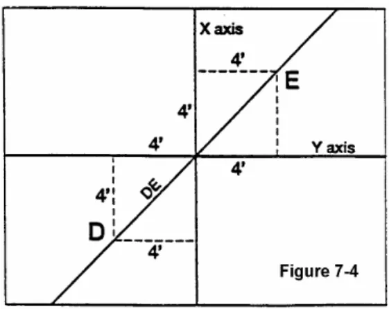
D. Diagonal Layout (See Figure 7-4)
1. Establish a 45-degree working line:
2. From the center point, measure 4 feet down in each direction on lines X and Y, which you have already determined by the method described above.
3. From each of these points, measure 4 feet and scribe an arc. The conjunction of these arcs creates points D and E.
4. Snap a chalk line between points D and E, and the center point. This line represents a 45-degree angle.
D. Herringbone Layout
1.Use reference lines throughout the area that is being installed.
Figure 7-5
2. The multiple of the width should equal the exact length of the piece. If the width of the product varies, this will cause separations at the end of the herringbone pieces.
3. Herringbone parquet can be laid out parallel or at a 45-degree angle to the room. Regardless of direction, Herringbone parquet will require a centerline and two working lines (See Figure 7-5).
4. Begin by laying out a few alternating slats. 5. Snap lines A & B through the corners of the alternating slats (See Figure 7-5)
6. Measure the distance from Line A to Line B. Line C should be ½ that distance and run parallel to Lines A & B. The centerline of the room and the center of the pattern is represented by Line C.
Figure 7-6 E. Herringbone Installation
1. To begin installation on working Line B (See Figure 7-6), cut a square piece of plywood the size of the herringbone pattern. For example, if the herringbone pattern is 3 inches by 12 inches, cut a 12” x 12” square of plywood. 2. Fasten the piece of plywood at your starting point on Line B, with one corner of the square pointing in the direction of the pattern.
Chapter 8 – Engineered Wood Flooring Installation
Copyright 2007 National Wood Flooring Association 7 REVISED APRIL 2008
CHAPTER 8
ENGINEERED WOOD
FLOORING INSTALLATION
Part I - Acceptable Jobsite Conditions and Jobsite Checklist
A. Refer to Chapter 1
Part II - Acclimation Guidelines
A. See Chapter 2 and Appendix B.
Part III – Appropriate Grade Levels
A. Engineered wood floors can be installed successfully on, above or below grade level. Engineered wood floors can be installed directly to concrete or wood subfloor.
B. The entire flooring level is considered to be BELOW grade where soil is present along any perimeter wall and is more than 3” above the installed wood flooring level. Ground should be sloped away from the house for proper drainage. (Check local building codes. Local building codes prevail. Follow local building codes.)
Part IV - Subfloors – Wood Joist Systems
A. See Chapter 4.
Part V - Subfloors – Concrete Slab
A. See Chapters 5-6.
Part VI – Engineered Flooring Installation Methods
A. Engineered wood flooring can be installed directly to screeds, provided the engineered flooring is a minimum of ¾” thick. For engineered flooring less than ¾” thick, the screed system must be overlaid with proper subflooring. See Appendix I, Installation Over Screeds.
B. Note on random-width plank
1. Random-width plank is laid out with alternating courses varying by widths. Start with the widest board, then the next width, etc., and repeat the pattern.
Grade Level diagram
If the soil surrounding a structure is 3 inches or more above the floor of any level, consider that level below grade. This includes walk-out basements. In addition, the surrounding soil should be sloped away from the structure.
Chapter 8 – Engineered Wood Flooring Installation
Copyright 2007 National Wood Flooring Association 8 REVISED APRIL 2008
C. Choose a Starting Wall
1. Choose a starting wall according to the most aesthetically or architecturally important elements in the room, taking into consideration fireplaces, doors, cabinets and transitions, as well as the squareness of the room. The starting wall will often be the longest unbroken wall in the room.
D. Glue-Down Engineered Strip and Plank
1. There are several different ways to start the installation of glue-down engineered wood flooring. The following has proven successful. However, where instructions differ from manufacturer recommendations, manufacturer recommendations prevail.
2. Test the substrate for moisture according to appropriate moisture testing procedures in Chapter 3. Excessive/elevated moisture should not be present. The subfloor should be within acceptable moisture content as per adhesive and wood manufacturer’s
recommendation before installing.
3. Expansion space should be left around the perimeter in accordance with the manufacturer’s recommendation.
4. Snap a working line parallel to the starting wall, the width of the board, plus the tongue and recommended expansion space.
5. Install a starter board along the edge of the working line and begin installation.
Alternatively, lay one row of plank in the adhesive along the length of the working line. 6. Follow manufacturer instruction for tongue and groove direction and placement.
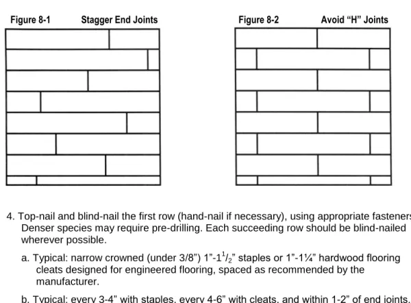
7. Use an adhesive approved by the flooring manufacturer. Follow the installation procedure recommended by the adhesive manufacturer, which includes subfloor moisture content, spread rate, trowel size, open time, working time and flash time as necessary. Spread the adhesive as instructed up to and along the working line. 8. Distribute lengths, avoiding “H” patterns and other discernible patterns in adjacent runs.
Stagger end joints of boards row to row a minimum of 6” for strip flooring, 8-10” for 3” to 5” plank, and 10” for plank wider than 5”. (See Figures 8-1 and 8-2.)
9. If recommended by the manufacturer, use tape or tensioners to maintain a tight floor. 10. If recommended by the adhesive manufacturer, roll the floor with the proper roller. E. Mechanically Fastened Strip and Plank
1. If necessary, add a vapor retarder.
2. Snap a working line parallel to the starting wall, allowing expansion space as specified by the manufacturer.
Chapter 8 – Engineered Wood Flooring Installation
Copyright 2007 National Wood Flooring Association 9 REVISED APRIL 2008
4. Top-nail and blind-nail the first row (hand-nail if necessary), using appropriate fasteners. Denser species may require pre-drilling. Each succeeding row should be blind-nailed wherever possible.
a. Typical: narrow crowned (under 3/8”) 1”-11
/2” staples or 1”-1¼” hardwood flooring
cleats designed for engineered flooring, spaced as recommended by the manufacturer.
b. Typical: every 3-4” with staples, every 4-6” with cleats, and within 1-2” of end joints. Use appropriate size fastener for top nailing first row, last row and any area where blind nailer will not fit.
5. Add each additional row of flooring. Distribute lengths, avoiding “H” patterns and other discernible patterns in adjacent runs.Stagger end joints of boards row to row a
minimum of 6” for strip flooring, 8-10” for 3” to 5” plank, and 10” for plank wider than 5”. 6. During installation of flooring pieces, push or gently tap boards flush to the previous row.
Tap against the tongue; tapping the groove may damage the edge. To prevent damage to the finish, avoid tapping the face of the board with a rubber mallet.
F. Floating Engineered Flooring
1. Subfloor flatness is critical to the success of a floating floor installation. (See Chapter 4, Wood Subfloor Guidelines, and Chapter 5, Concrete Subfloor Guidelines.)
2. Test the substrate for moisture according to appropriate moisture testing procedures in Chapter 3. Excessive/elevated moisture should not be present. The subfloor should be within acceptable moisture content as per manufacturer recommendation before installing.
4. If necessary, add vapor retarder. (See Acceptable Vapor Retarders in Chapter 3, Moisture Requirements and Moisture Testing.)
5. Expansion space should be left around the perimeter or in accordance with manufacturer’s recommendation.
Chapter 8 – Engineered Wood Flooring Installation
Copyright 2007 National Wood Flooring Association 10 REVISED APRIL 2008
6. Typical: Subfloors are covered with a resilient material, foam underlayment or cork. Follow manufacturer's instructions for correct materials and thickness.
7. Typical: floating engineered flooring is edge-glued or edge-attached with a self-locking mechanism.
a. For edge-glued products, use an adhesive approved by the manufacturer.
b. Apply adhesive at the spread rate to the side grooves and/or ends as recommended by the manufacturer.
8. Starter boards should be aligned with the groove side and end against the starting wall. Tapping block should be used against tongue only.
Chapter 9 – Solid Strip & Plank Flooring Installation
Copyright 2007 National Wood Flooring Association 11 REVISED APRIL 2008
CHAPTER 9
SOLID STRIP AND PLANK
FLOORING INSTALLATION
Part I - Acceptable Jobsite Conditions and Jobsite Checklist
A. Refer to Chapter 1
Part II - Acclimation Guidelines
A. See Chapter 2 and Appendix B.
Part III – Appropriate Grade Levels
A. Solid strip and plank wood floors can be installed successfully above grade level or on grade, but are not
recommended for installation below grade.
B. The entire flooring level is considered to be BELOW GRADE where soil is present along any perimeter wall and is more than 3” above the installed wood flooring level. Ground should be sloped away from the house for proper drainage. (Follow local building
codes.)
Part IV - Subfloors – Wood Joist Systems
A. See Chapter 4.
Part V - Subfloors – Concrete Slab
A. See Chapter 5.
B. When installing solid strip and solid plank flooring over concrete, a vapor retarder is always required over the concrete slab and below the subflooring material. A minimum 6 mil construction grade polyethylene film, with perm of .13, or other impermeable material with a perm of .15 or less is recommended.
C. Some manufacturers allow direct glue installation of ¾” solid strip and solid plank flooring. In such cases, follow manufacturer’s recommendation.
Grade Level diagram
If the soil surrounding a structure is 3 inches or more above the floor of any level, consider that level below grade. This includes walk-out basements. In addition, the surrounding soil should be sloped away from the structure.
Chapter 9 – Solid Strip & Plank Flooring Installation
Copyright 2007 National Wood Flooring Association 12 REVISED APRIL 2008
Part VI – Solid Strip & Plank Installation Methods
A. Always follow the manufacturer’s recommended installation procedure.
B. Unfinished and factory-finished solid strip and solid plank flooring should be installed perpendicular to the joists or on a diagonal for any single layer subfloor. (Exception: Over diagonal, solid subfloor boards, install perpendicular to joists or subfloor direction.)
C. When ¾" solid strip and solid plank flooring is laid parallel with the floor joists, follow one of these two steps:
1. Add a layer of minimum nominal ½" (15/32”) CD Exposure 1 (CDX) plywood underlayment to the existing subfloor (as previously recommended)
2. Or brace between truss/joists in accordance with the truss/joist manufacturer’s recommendations and with local building codes. Some truss/joist systems cannot be cross-braced and still maintain stability.
D. Before installing wood flooring, place an approved vapor retarder. Some examples of acceptable vapor retarders over wood subfloors include:
1. An asphalt laminated paper meeting UU-B-790a, Grade B, Type I, Style 1a.
2. Asphalt-saturated kraft paper or #15 or #30 felt that meets ASTM Standard D-4869 or UU-B-790, Grade D.
E. Wall Line Layout
1. Choose a starting wall according to the most aesthetically or architecturally important elements in the room, taking into consideration fireplaces, doors, cabinets and transitions, as well as the squareness of the room. The starting wall will often be the longest unbroken wall in the room.
2. Snap a working line parallel to the starting wall, allowing ¾” expansion space between the starting wall and the edge of the first strip or plank run.
3. As a general rule, a ¾” expansion space must be left around the perimeter and at all vertical obstructions.
4. Random-width plank is laid out with alternating courses varying by widths. Start with the widest board, then the next width, etc., and repeat the pattern.
5. Lay one row of strip or plank along the entire length of the working line.
6. Top-nail and blind-nail the first row (hand-nail if necessary), using appropriate fasteners. Denser species may require pre-drilling. Each succeeding row should be blind-nailed with the nailing machine wherever possible. At the finishing wall and other obstructions, it may be necessary to blind-nail by hand until top nailing is required.
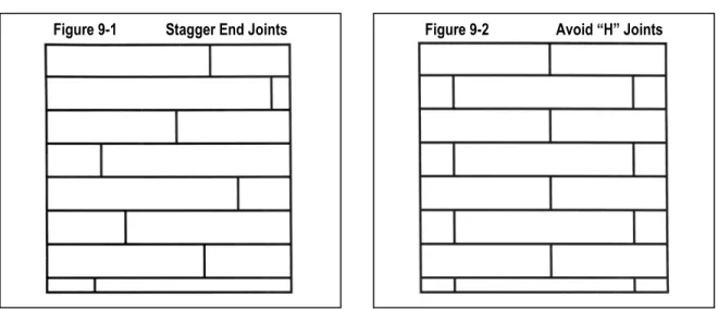
7. Racking rule of thumb: Avoid ”H” patterns. Stagger end joints of boards row to row a minimum of 6” for strip flooring, 8-10” for 3” to 5” plank, and 10” for plank wider than 5”.See Figures 9-1 and 9-2.
8. To minimize expansion on floors wider than 20 feet, more or less spacing between rows may be needed, depending on geographical area, interior climate control and time of the year. (Appendix B, Acclimation.)
Chapter 9 – Solid Strip & Plank Flooring Installation
Copyright 2007 National Wood Flooring Association 13 REVISED APRIL 2008
9. Where spacing is required: Use a washer or removable spacer to leave additional space every few rows and/or start in center of room and work out to both sides. Do not use spacers that may cause damage on factory-finished products.
10. Nailing: Blind-nail through the tongue using 1½"-2” fasteners. Use 1½" fasteners with nominal ¾" plywood subfloor direct to concrete slab. Face-nail boards where needed using 6d-8d casing or finish nails. Fasteners should be spaced every 6”-8” on blind-nailing, or every 10”-12” on face-nailing.
11. For additional fastening, any of the following options may be used in addition to the nailing schedule. (See Appendix F, Fastener Schedule.)
12. Follow manufacturer’s instructions for installing plank flooring.
13. For wide-width plank flooring (5” or wider), to assist the nailing schedule of 6”-8” and increase holding power, there are three options.
a. Screw and plug at end joints, alternating at staggered locations and intervals along each board.
b. Apply an approved wood flooring adhesive.
c. Use kerfing or relief cuts every 8” to 12” parallel to the grain – using more relief cuts for wider boards. Typically, the relief cut should be 3/8” on a ¾” board.
NOTE: These options, however, will not necessarily eliminate cupping.
14. Blind-nail and face-nail, as necessary, to complete the final rows. F. Center Line Layout
NOTE: For instructions on using the trammel point method to square a room and find the center point, see Appendix G, Trammel Point Method.
1. Find the center of your room, measuring off the two longest walls, and snap a line down the center of that room.
Chapter 9 – Solid Strip & Plank Flooring Installation
Copyright 2007 National Wood Flooring Association 14 REVISED APRIL 2008
2. Install a starter board on the line. Fasten the starter board to the floor using wood screws.
3. Nail the first row of wood flooring against the starter board, being careful not to move the starter board when nailing. The groove of the flooring should be against the starter board.
4. Drill and hand-nail the first three rows through the tongue. DO NOT USE TOP NAILS. 5. Use a blind nailer to install the remaining rows of wood flooring. Use the nailing practices
described earlier in the chapter.
6. After installing in one direction, remove the starter board and start rows going in the opposite direction.
7. Install a spline or a slip tongue in the groove of the board that was against the straight-edge. Put wood flooring adhesive down the entire length of the groove before installing the spline.
8. Install the spline using a blind nailer. To keep the spline in alignment for the next flooring board, use a scrap piece of wood flooring to run along the length of the spline as you nail.
9. Install the remaining rows in the opposite direction. Use the nailing practices described earlier in the chapter.
Chapter 10 – Installation Over Existing Floors
Copyright 2007 National Wood Flooring Association 15 REVISED APRIL 2008
CHAPTER 10
INSTALLATION OVER
EXISTING FLOORS
Part I – Existing Floor Requirements
A. Always follow the manufacturers recommendations for installation over existing flooring B. Glue-down parquet applications that require the use of PVA adhesives are not
recommended over existing sheet vinyl or vinyl and cork tile flooring unless an underlayment is put down first. Underlayment should be in accordance with adhesive and/or flooring manufacturer’s recommendations.
C. Particleboard is not generally an acceptable underlayment, because it lacks stability. Some manufacturers approve particleboard as an acceptable underlayment, as they do not warrant against subfloor movement. In such cases, follow manufacturer’s
recommendation.
D. Other types of adhesives may require the use of a primer or vinyl blocker when installing over sheet vinyl or vinyl and cork tile flooring. Follow manufacturer’s recommendations. E. Nail-down applications may be successful over existing sheet vinyl or vinyl tile if fastener
penetration is not significantly diminished and the subfloor meets minimum requirements. Fasteners must penetrate a proper subfloor by at least 5/8”.
F. Wood flooring can be installed over existing ceramic tile, terrazzo, or marble with proper underlayment or adhesives only on manufacturer's recommendation.
G. Installing wood flooring over an existing wood floor.
1. Sand off old finish and high spots on existing wood floor and prep to clean, dry, sound, flat subfloor. Repair, re-nail or replace loose flooring products.
2. Over an existing glue-down floor, glue direct to the existing floor. Or, if the thickness of the floor will allow it, staple to the existing floor. Check with the flooring
manufacturer for recommendations.
3. When installing new wood flooring parallel to an existing solid nail-down floor, add a minimum of 3/8” underlayment over the existing floor to increase stability. Check with
the flooring manufacturer for recommendations.
4. When installing new wood flooring at a 45- to 90-degree angle to an existing solid nail-down floor, additional underlayment is not required.
Copyright 2007 National Wood Flooring Association Revised March 2007
SECTION IV
APPENDICES
Appendix A
SAFETY GUIDELINES ...Page 1
Appendix B
ACCLIMATION ...Page 3
Appendix C
MOISTURE GUIDELINES & MOISTURE TESTING ...Page 7
Appendix D
MOISTURE BY AREA – US ...Page 13
Appendix E
MOISTURE BY AREA – CANADA ...Page 15
Appendix F
FASTENER SCHEDULE ...Page 17
Appendix G
TRAMMEL POINT METHOD ...Page19
Appendix H
RADIANT HEAT INSTALLATIONS ...Page 21
Appendix I
INSTALLATION OVER SCREEDS ...Page 27
Appendix J
SOUND CONTROL ...Page 29
Appendix K
TRIM & THRESHOLDS ...Page 31
Appendix L
SAMPLE SPECIFICATION ...Page 33
Appendix M
JOBSITE CHECKLIST ...Page 37
Appendix A – Safety Guidelines
APPENDIX A
SAFETY GUIDELINES
Safety first
Safety on the job is the foremost concern for contractors, because accidents with power tools can be critical, even disabling or deadly. No amount of experience or expertise exempts you from safety risks inherent in using the tools required to install hardwood floors. The goods news is that these risks are easily managed. Start with these general guidelines:
• Never work under the influence of alcohol, drugs or medication • Work with others nearby, if possible.
• Do not work on a cluttered floor. • Use proper lighting and ventilation.
• Make sure that the electrical power and wiring at the jobsite is sufficient to operate all machines safely.
• Know your insurance company’s policy on coverage related to accidents or jobsite situations. • Wear proper work clothing and shoes. Do not wear loose clothing that could get caught in a
machine.
• Wear NIOSH-approved approved hearing protection and safety glasses, as well as dust and fume respirators, knee protection and gloves.
• Have an OSHA-approved first-aid kit on the job site.
• Read and fully understand the owner’s manuals that are supplied with the equipment. • Use tools only as intended.
• Use all tool and machine safety guards.
• Turn off and unplug electrical tools and machines when making adjustments and attaching accessories.
• Turn off all sources of ignition when using flammables.
• Use ground fault circuit interrupters (GFCIs) on electric tools to avoid electric shock. • Carry and read MSDS (Material Safety Data Sheets) for all products.
• Do not exceed manufacturer’s recommended working air pressure for pneumatic systems.